2001 DODGE TOWN AND COUNTRY air condition
[x] Cancel search: air conditionPage 1293 of 2321
OIL PAN
REMOVAL
(1) Disconnect negative cable from battery and
remove engine oil dipstick.
(2) Raise vehicle on hoist and drain engine oil.
(3) Remove drive belt splash shield.
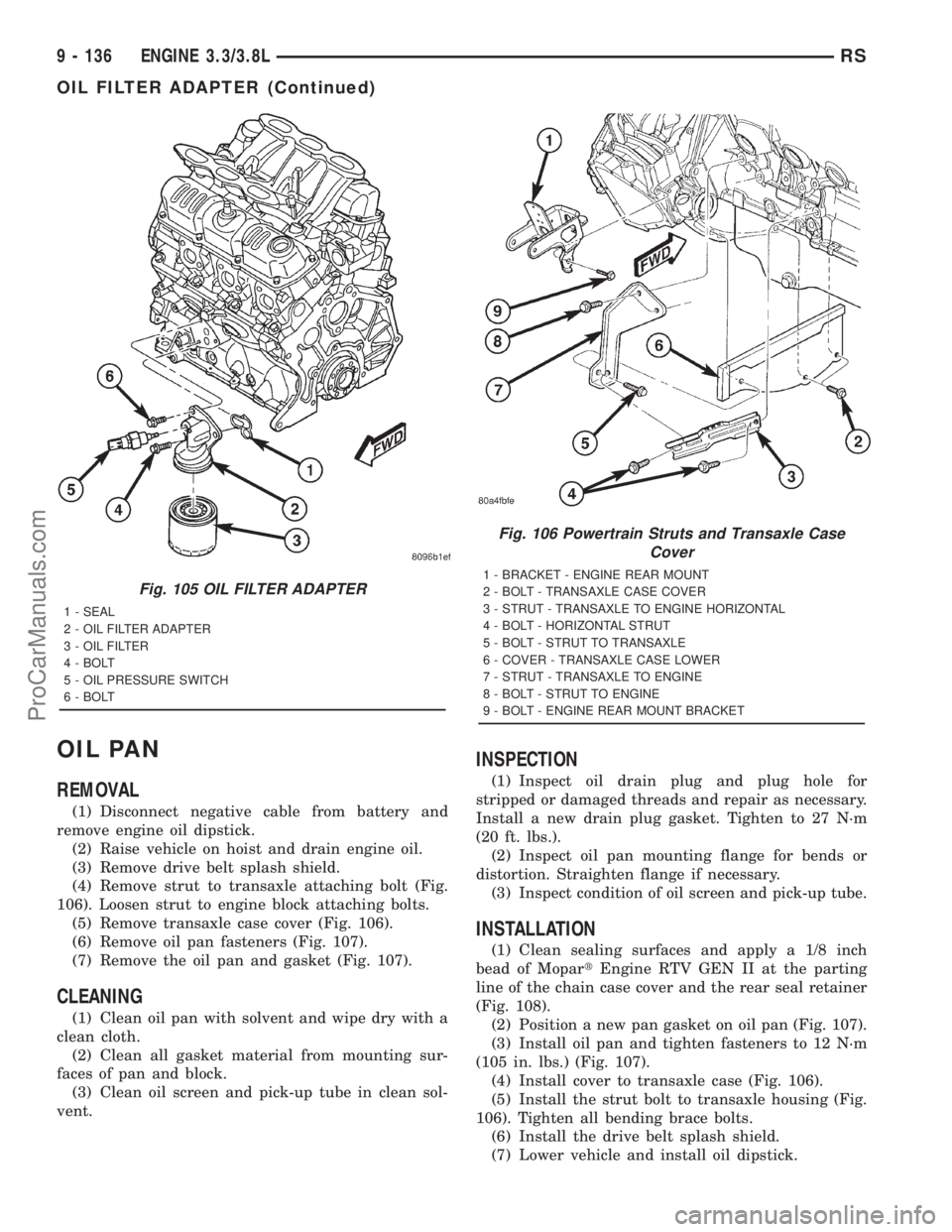
(4) Remove strut to transaxle attaching bolt (Fig.
106). Loosen strut to engine block attaching bolts.
(5) Remove transaxle case cover (Fig. 106).
(6) Remove oil pan fasteners (Fig. 107).
(7) Remove the oil pan and gasket (Fig. 107).
CLEANING
(1) Clean oil pan with solvent and wipe dry with a
clean cloth.
(2) Clean all gasket material from mounting sur-
faces of pan and block.
(3) Clean oil screen and pick-up tube in clean sol-
vent.
INSPECTION
(1) Inspect oil drain plug and plug hole for
stripped or damaged threads and repair as necessary.
Install a new drain plug gasket. Tighten to 27 N´m
(20 ft. lbs.).
(2) Inspect oil pan mounting flange for bends or
distortion. Straighten flange if necessary.
(3) Inspect condition of oil screen and pick-up tube.
INSTALLATION
(1) Clean sealing surfaces and apply a 1/8 inch
bead of MopartEngine RTV GEN II at the parting
line of the chain case cover and the rear seal retainer
(Fig. 108).
(2) Position a new pan gasket on oil pan (Fig. 107).
(3) Install oil pan and tighten fasteners to 12 N´m
(105 in. lbs.) (Fig. 107).
(4) Install cover to transaxle case (Fig. 106).
(5) Install the strut bolt to transaxle housing (Fig.
106). Tighten all bending brace bolts.
(6) Install the drive belt splash shield.
(7) Lower vehicle and install oil dipstick.
Fig. 105 OIL FILTER ADAPTER
1 - SEAL
2 - OIL FILTER ADAPTER
3 - OIL FILTER
4 - BOLT
5 - OIL PRESSURE SWITCH
6 - BOLT
Fig. 106 Powertrain Struts and Transaxle Case
Cover
1 - BRACKET - ENGINE REAR MOUNT
2 - BOLT - TRANSAXLE CASE COVER
3 - STRUT - TRANSAXLE TO ENGINE HORIZONTAL
4 - BOLT - HORIZONTAL STRUT
5 - BOLT - STRUT TO TRANSAXLE
6 - COVER - TRANSAXLE CASE LOWER
7 - STRUT - TRANSAXLE TO ENGINE
8 - BOLT - STRUT TO ENGINE
9 - BOLT - ENGINE REAR MOUNT BRACKET
9 - 136 ENGINE 3.3/3.8LRS
OIL FILTER ADAPTER (Continued)
ProCarManuals.com
Page 1298 of 2321
between cylinder heads and houses the coolant ther-
mostat (Fig. 121).
The intake manifold utilizes a compact design with
very low restriction and outstanding flow balance.
This design allows the engine to perform with a wide
torque curve while increasing higher rpm horse-
power.
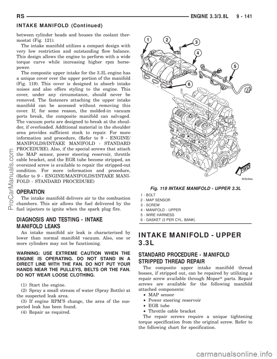
The composite upper intake for the 3.3L engine has
a unique cover over the upper portion of the manifold
(Fig. 119). This cover is designed to absorb intake
noises and also offers styling to the engine. This
cover, under any circumstance, should never be
removed. The fasteners attaching the upper intake
manifold can be accessed without removing this
cover. If, for some reason, the molded-in vacuum
ports break, the composite manifold can salvaged.
The vacuum ports are designed to break at the shoul-
der, if overloaded. Additional material in the shoulder
area provides sufficient stock to repair. For more
information and procedure, (Refer to 9 - ENGINE/
MANIFOLDS/INTAKE MANIFOLD - STANDARD
PROCEDURE). Also, if the special screws that attach
the MAP sensor, power steering reservoir, throttle
cable bracket, and the EGR tube become stripped, an
oversized screw is available to repair the stripped-out
condition. For more information and procedure,
(Refer to 9 - ENGINE/MANIFOLDS/INTAKE MANI-
FOLD - STANDARD PROCEDURE)
OPERATION
The intake manifold delivers air to the combustion
chambers. This air allows the fuel delivered by the
fuel injectors to ignite when the spark plug fire.
DIAGNOSIS AND TESTING - INTAKE
MANIFOLD LEAKS
An intake manifold air leak is characterized by
lower than normal manifold vacuum. Also, one or
more cylinders may not be functioning.
WARNING: USE EXTREME CAUTION WHEN THE
ENGINE IS OPERATING. DO NOT STAND IN A
DIRECT LINE WITH THE FAN. DO NOT PUT YOUR
HANDS NEAR THE PULLEYS, BELTS OR THE FAN.
DO NOT WEAR LOOSE CLOTHING.
(1) Start the engine.
(2) Spray a small stream of water (Spray Bottle) at
the suspected leak area.
(3) If engine RPM'S change, the area of the sus-
pected leak has been found.
(4) Repair as required.INTAKE MANIFOLD - UPPER
3.3L
STANDARD PROCEDURE - MANIFOLD
STRIPPED THREAD REPAIR
The composite upper intake manifold thread
bosses, if stripped out, can be repaired by utilizing a
repair screw available through Mopartparts. Repair
screws are available for the following manifold
attached components:
²MAP sensor
²Power steering reservoir
²EGR tube
²Throttle cable bracket
The repair screws require a unique tightening
torque specification from the original screw. Refer to
the following chart for specification.
Fig. 119 INTAKE MANIFOLD - UPPER 3.3L
1 - BOLT
2 - MAP SENSOR
3 - SCREW
4 - MANIFOLD - UPPER
5 - WIRE HARNESS
6 - GASKET (3 PER CYL. BANK)
RSENGINE 3.3/3.8L9 - 141
INTAKE MANIFOLD (Continued)
ProCarManuals.com
Page 1301 of 2321
CLEANING
(1) Discard gasket(s).
(2) Clean all sealing surfaces.
INSPECTION
Check manifold for:
²Damage and cracks.
²Mounting surface distortion by using a straight-
edge and thickness gauge.
INSTALLATION - 3.3L
(1) If the following components were removed from
manifold, install and tighten to specifications:
CAUTION: The special screws used for the compos-
ite manifold attached components must be installed
slowly using hand tools only. This requirement is to
prevent the melting of material that causes stripped
threads. If threads become stripped, an oversize
repair screw is available. For more information and
procedure (Refer to 9 - ENGINE/MANIFOLDS/IN-
TAKE MANIFOLD - STANDARD PROCEDURE).
²MAP sensor - 1.7 N´m (15 in. lbs.)
²Throttle cable bracket - 5.6 N´m (50 in. lbs.)
(2) Remove covering on lower intake manifold and
clean surfaces.
(3) Inspect manifold gasket condition. Gaskets can
be re-used, if not damaged. To replace, remove gasket
from upper manifold (Fig. 127). Position new gasket
in seal channel and press lightly in-place. Repeat
procedure for each gasket position.
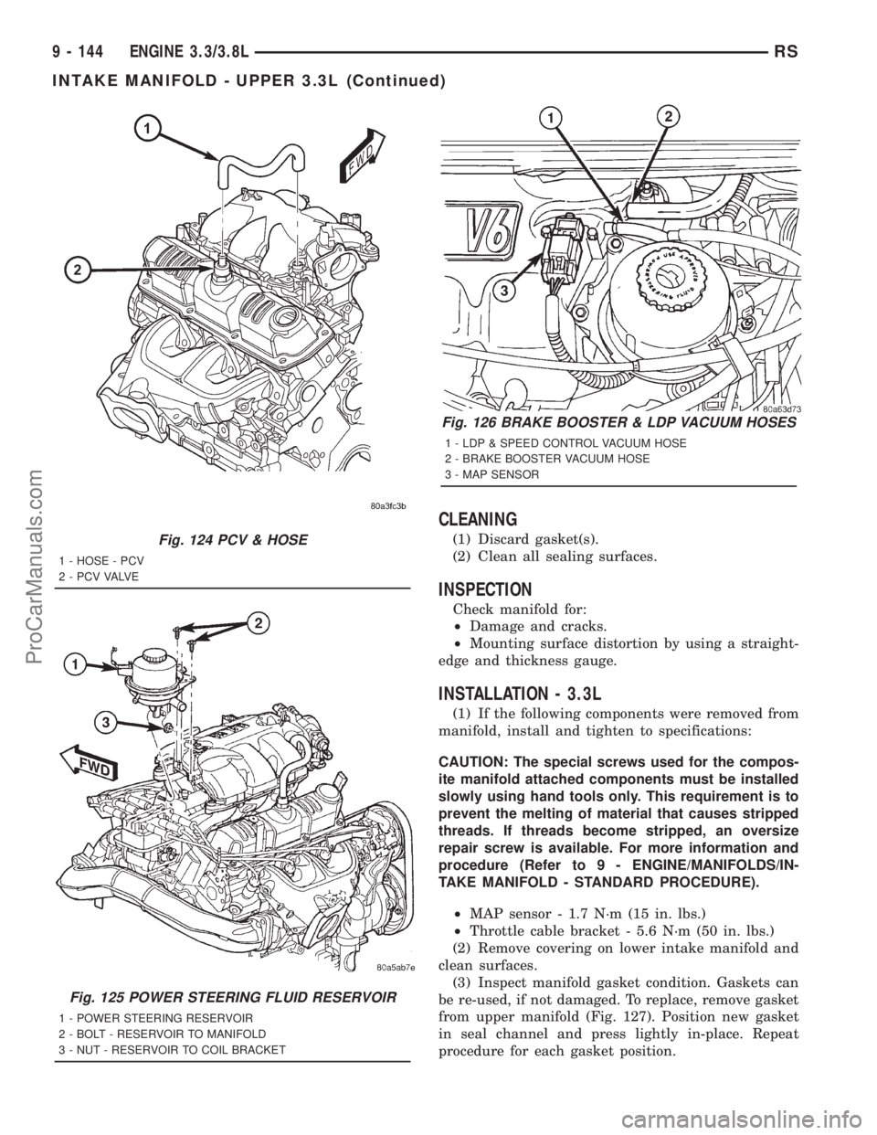
Fig. 124 PCV & HOSE
1 - HOSE - PCV
2 - P C V VA LV E
Fig. 125 POWER STEERING FLUID RESERVOIR
1 - POWER STEERING RESERVOIR
2 - BOLT - RESERVOIR TO MANIFOLD
3 - NUT - RESERVOIR TO COIL BRACKET
Fig. 126 BRAKE BOOSTER & LDP VACUUM HOSES
1 - LDP & SPEED CONTROL VACUUM HOSE
2 - BRAKE BOOSTER VACUUM HOSE
3 - MAP SENSOR
9 - 144 ENGINE 3.3/3.8LRS
INTAKE MANIFOLD - UPPER 3.3L (Continued)
ProCarManuals.com
Page 1320 of 2321
(24) Disconnect egr solenoid vacuum line at brake
booster check valve.
(25) Disconnect fuel injector, cam sensor, boost
pressure/intake air temp sensor, fuel rail high pres-
sure, and egr solenoid connectors (Fig. 9).
(26) Disconnect generator electrical connectors.
(27) Disconnect coolant temp sensor and glow plug
electrical connectors.
(28) Disconnect injection pump and A/C compres-
sor electrical connectors.
(29) Disconnect starter electrical connectors.
(30) Disconnect ground wires at engine block.
(31) Raise vehicle on hoist.
(32) Disconnect oil temp sensor, oil pressure sen-
sor, engine speed sensor, and vehicle speed sensor
electrical connector (Fig. 10).
(33) Remove front wheels.
(34) Remove the suspension cradle assembly (Refer
to 13 - FRAME & BUMPERS/FRAME/ENGINE
CRADLE CROSSMEMBER - REMOVAL).
(35) Remove both axle shaft assemblies (Refer to 3
- DIFFERENTIAL & DRIVELINE/HALF SHAFT -
REMOVAL).(36) Disconnect the clutch slave cylinder quick dis-
connect line (RHD only)(Refer to 6 - CLUTCH/SLAVE
CYLINDER - REMOVAL).
(37) Disconnect reverse lamp connector.
(38) Disconnect shifter cables at the tranmission
(Refer to 21 - TRANSMISSION/TRANSAXLE/MAN-
UAL/GEAR SHIFT CABLE - REMOVAL).
(39) Disconnect exhaust pipe from the turbo-
charger downpipe and reposition to right side of vehi-
cle.
(40) Disconnect cabin heater coolant line (Refer to
24 - HEATING & AIR CONDITIONING/CABIN
HEATER/HEATER UNIT - REMOVAL).
(41) Remove front engine mount bracket retaining
bolts from lower radiator support
(42) Lower vehicle. Evacuate the A/C system
(Refer to 24 - HEATING & AIR CONDITIONING/
PLUMBING/REFRIGERANT - STANDARD PROCE-
DURE).
(43) Disconnect the A/C lines at the A/C compres-
sor.
(44) Disconnect the fuel supply and return lines.
(45) Position engine cradle under engine and lower
vehicle over cradle.
(46) Remove right engine mount bolts.
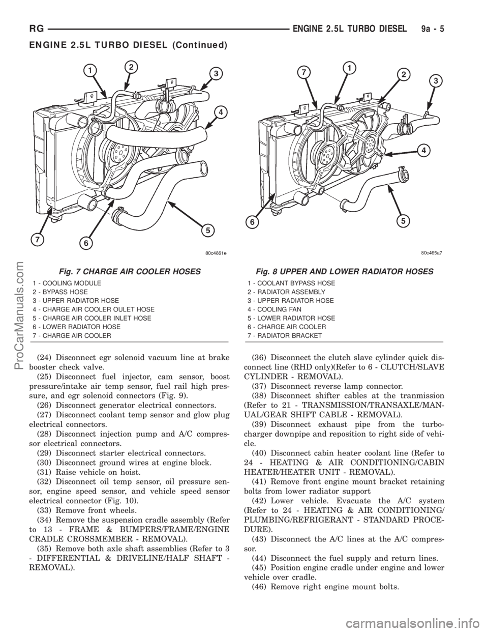
Fig. 7 CHARGE AIR COOLER HOSES
1 - COOLING MODULE
2 - BYPASS HOSE
3 - UPPER RADIATOR HOSE
4 - CHARGE AIR COOLER OULET HOSE
5 - CHARGE AIR COOLER INLET HOSE
6 - LOWER RADIATOR HOSE
7 - CHARGE AIR COOLER
Fig. 8 UPPER AND LOWER RADIATOR HOSES
1 - COOLANT BYPASS HOSE
2 - RADIATOR ASSEMBLY
3 - UPPER RADIATOR HOSE
4 - COOLING FAN
5 - LOWER RADIATOR HOSE
6 - CHARGE AIR COOLER
7 - RADIATOR BRACKET
RGENGINE 2.5L TURBO DIESEL9a-5
ENGINE 2.5L TURBO DIESEL (Continued)
ProCarManuals.com
Page 1322 of 2321
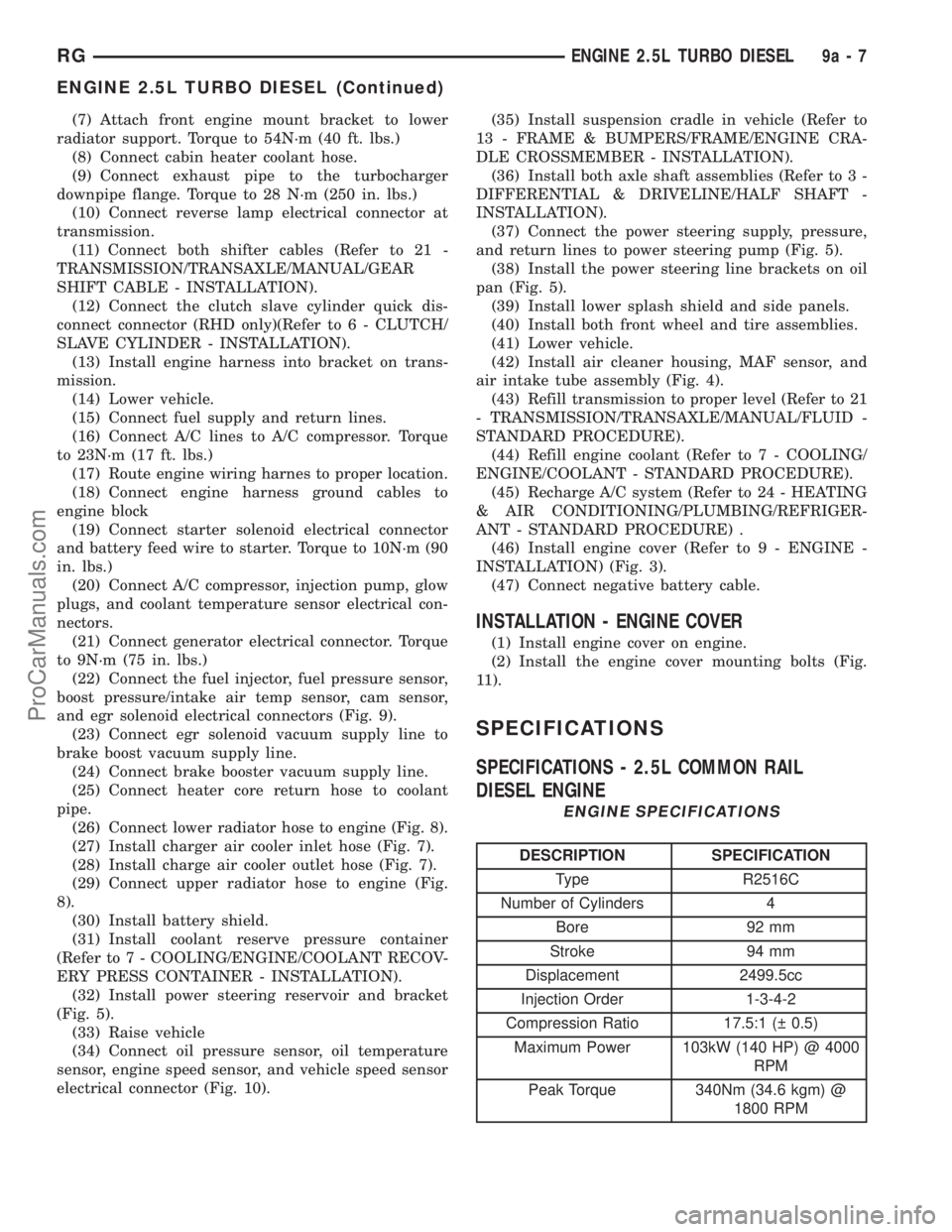
(7) Attach front engine mount bracket to lower
radiator support. Torque to 54N´m (40 ft. lbs.)
(8) Connect cabin heater coolant hose.
(9) Connect exhaust pipe to the turbocharger
downpipe flange. Torque to 28 N´m (250 in. lbs.)
(10) Connect reverse lamp electrical connector at
transmission.
(11) Connect both shifter cables (Refer to 21 -
TRANSMISSION/TRANSAXLE/MANUAL/GEAR
SHIFT CABLE - INSTALLATION).
(12) Connect the clutch slave cylinder quick dis-
connect connector (RHD only)(Refer to 6 - CLUTCH/
SLAVE CYLINDER - INSTALLATION).
(13) Install engine harness into bracket on trans-
mission.
(14) Lower vehicle.
(15) Connect fuel supply and return lines.
(16) Connect A/C lines to A/C compressor. Torque
to 23N´m (17 ft. lbs.)
(17) Route engine wiring harnes to proper location.
(18) Connect engine harness ground cables to
engine block
(19) Connect starter solenoid electrical connector
and battery feed wire to starter. Torque to 10N´m (90
in. lbs.)
(20) Connect A/C compressor, injection pump, glow
plugs, and coolant temperature sensor electrical con-
nectors.
(21) Connect generator electrical connector. Torque
to 9N´m (75 in. lbs.)
(22) Connect the fuel injector, fuel pressure sensor,
boost pressure/intake air temp sensor, cam sensor,
and egr solenoid electrical connectors (Fig. 9).
(23) Connect egr solenoid vacuum supply line to
brake boost vacuum supply line.
(24) Connect brake booster vacuum supply line.
(25) Connect heater core return hose to coolant
pipe.
(26) Connect lower radiator hose to engine (Fig. 8).
(27) Install charger air cooler inlet hose (Fig. 7).
(28) Install charge air cooler outlet hose (Fig. 7).
(29) Connect upper radiator hose to engine (Fig.
8).
(30) Install battery shield.
(31) Install coolant reserve pressure container
(Refer to 7 - COOLING/ENGINE/COOLANT RECOV-
ERY PRESS CONTAINER - INSTALLATION).
(32) Install power steering reservoir and bracket
(Fig. 5).
(33) Raise vehicle
(34) Connect oil pressure sensor, oil temperature
sensor, engine speed sensor, and vehicle speed sensor
electrical connector (Fig. 10).(35) Install suspension cradle in vehicle (Refer to
13 - FRAME & BUMPERS/FRAME/ENGINE CRA-
DLE CROSSMEMBER - INSTALLATION).
(36) Install both axle shaft assemblies (Refer to 3 -
DIFFERENTIAL & DRIVELINE/HALF SHAFT -
INSTALLATION).
(37) Connect the power steering supply, pressure,
and return lines to power steering pump (Fig. 5).
(38) Install the power steering line brackets on oil
pan (Fig. 5).
(39) Install lower splash shield and side panels.
(40) Install both front wheel and tire assemblies.
(41) Lower vehicle.
(42) Install air cleaner housing, MAF sensor, and
air intake tube assembly (Fig. 4).
(43) Refill transmission to proper level (Refer to 21
- TRANSMISSION/TRANSAXLE/MANUAL/FLUID -
STANDARD PROCEDURE).
(44) Refill engine coolant (Refer to 7 - COOLING/
ENGINE/COOLANT - STANDARD PROCEDURE).
(45) Recharge A/C system (Refer to 24 - HEATING
& AIR CONDITIONING/PLUMBING/REFRIGER-
ANT - STANDARD PROCEDURE) .
(46) Install engine cover (Refer to 9 - ENGINE -
INSTALLATION) (Fig. 3).
(47) Connect negative battery cable.
INSTALLATION - ENGINE COVER
(1) Install engine cover on engine.
(2) Install the engine cover mounting bolts (Fig.
11).
SPECIFICATIONS
SPECIFICATIONS - 2.5L COMMON RAIL
DIESEL ENGINE
ENGINE SPECIFICATIONS
DESCRIPTION SPECIFICATION
Type R2516C
Number of Cylinders 4
Bore 92 mm
Stroke 94 mm
Displacement 2499.5cc
Injection Order 1-3-4-2
Compression Ratio 17.5:1 ( 0.5)
Maximum Power 103kW (140 HP) @ 4000
RPM
Peak Torque 340Nm (34.6 kgm) @
1800 RPM
RGENGINE 2.5L TURBO DIESEL9a-7
ENGINE 2.5L TURBO DIESEL (Continued)
ProCarManuals.com
Page 1383 of 2321
CATALYTIC CONVERTER
DESCRIPTION
The toe board three-way catalytic converter is con-
nected to the exhaust manifold by the use of flex
joint and a gasket. The outlet connects to the muffler
inlet pipe and is secured with a band type clamp
(Fig. 1).
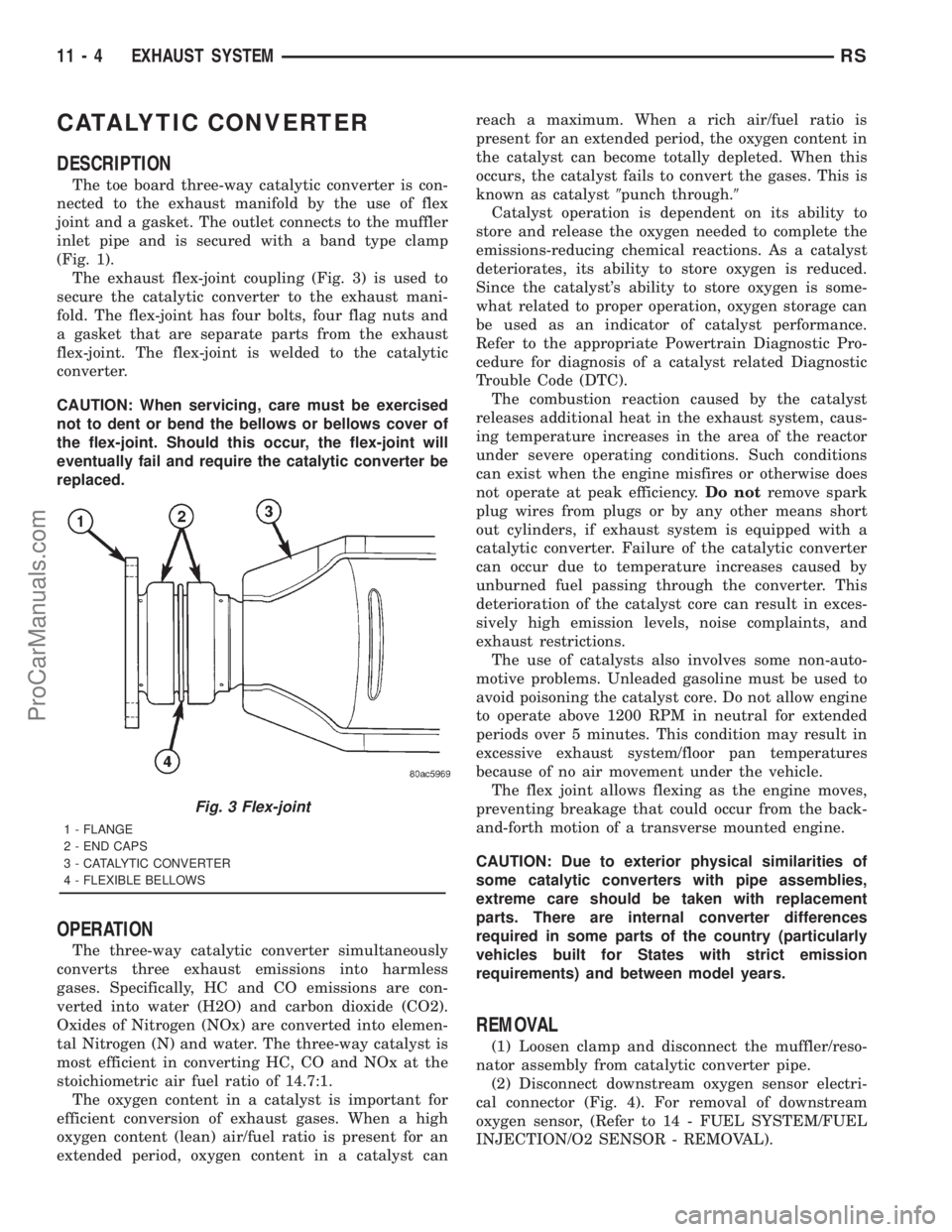
The exhaust flex-joint coupling (Fig. 3) is used to
secure the catalytic converter to the exhaust mani-
fold. The flex-joint has four bolts, four flag nuts and
a gasket that are separate parts from the exhaust
flex-joint. The flex-joint is welded to the catalytic
converter.
CAUTION: When servicing, care must be exercised
not to dent or bend the bellows or bellows cover of
the flex-joint. Should this occur, the flex-joint will
eventually fail and require the catalytic converter be
replaced.
OPERATION
The three-way catalytic converter simultaneously
converts three exhaust emissions into harmless
gases. Specifically, HC and CO emissions are con-
verted into water (H2O) and carbon dioxide (CO2).
Oxides of Nitrogen (NOx) are converted into elemen-
tal Nitrogen (N) and water. The three-way catalyst is
most efficient in converting HC, CO and NOx at the
stoichiometric air fuel ratio of 14.7:1.
The oxygen content in a catalyst is important for
efficient conversion of exhaust gases. When a high
oxygen content (lean) air/fuel ratio is present for an
extended period, oxygen content in a catalyst canreach a maximum. When a rich air/fuel ratio is
present for an extended period, the oxygen content in
the catalyst can become totally depleted. When this
occurs, the catalyst fails to convert the gases. This is
known as catalyst9punch through.9
Catalyst operation is dependent on its ability to
store and release the oxygen needed to complete the
emissions-reducing chemical reactions. As a catalyst
deteriorates, its ability to store oxygen is reduced.
Since the catalyst's ability to store oxygen is some-
what related to proper operation, oxygen storage can
be used as an indicator of catalyst performance.
Refer to the appropriate Powertrain Diagnostic Pro-
cedure for diagnosis of a catalyst related Diagnostic
Trouble Code (DTC).
The combustion reaction caused by the catalyst
releases additional heat in the exhaust system, caus-
ing temperature increases in the area of the reactor
under severe operating conditions. Such conditions
can exist when the engine misfires or otherwise does
not operate at peak efficiency.Do notremove spark
plug wires from plugs or by any other means short
out cylinders, if exhaust system is equipped with a
catalytic converter. Failure of the catalytic converter
can occur due to temperature increases caused by
unburned fuel passing through the converter. This
deterioration of the catalyst core can result in exces-
sively high emission levels, noise complaints, and
exhaust restrictions.
The use of catalysts also involves some non-auto-
motive problems. Unleaded gasoline must be used to
avoid poisoning the catalyst core. Do not allow engine
to operate above 1200 RPM in neutral for extended
periods over 5 minutes. This condition may result in
excessive exhaust system/floor pan temperatures
because of no air movement under the vehicle.
The flex joint allows flexing as the engine moves,
preventing breakage that could occur from the back-
and-forth motion of a transverse mounted engine.
CAUTION: Due to exterior physical similarities of
some catalytic converters with pipe assemblies,
extreme care should be taken with replacement
parts. There are internal converter differences
required in some parts of the country (particularly
vehicles built for States with strict emission
requirements) and between model years.
REMOVAL
(1) Loosen clamp and disconnect the muffler/reso-
nator assembly from catalytic converter pipe.
(2) Disconnect downstream oxygen sensor electri-
cal connector (Fig. 4). For removal of downstream
oxygen sensor, (Refer to 14 - FUEL SYSTEM/FUEL
INJECTION/O2 SENSOR - REMOVAL).
Fig. 3 Flex-joint
1 - FLANGE
2 - END CAPS
3 - CATALYTIC CONVERTER
4 - FLEXIBLE BELLOWS
11 - 4 EXHAUST SYSTEMRS
ProCarManuals.com
Page 1419 of 2321
(5) Connect negative cable to battery or auxiliary
jumper terminal.
CAUTION: When using the ASD Fuel System Test,
the Auto Shutdown (ASD) Relay remains energized
for several minutes, until the test is stopped, or
until the ignition switch is turned to the Off posi-
tion.
(6) Use the DRB IIItscan tool ASD Fuel System
Test to pressurize the fuel system. Check for leaks.
TWO-TAB TYPE FITTING
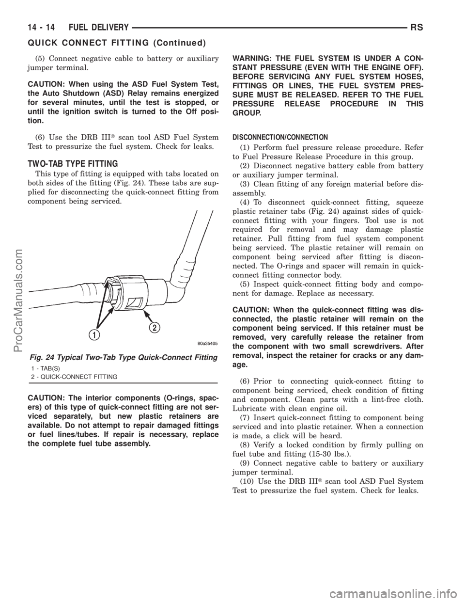
This type of fitting is equipped with tabs located on
both sides of the fitting (Fig. 24). These tabs are sup-
plied for disconnecting the quick-connect fitting from
component being serviced.
CAUTION: The interior components (O-rings, spac-
ers) of this type of quick-connect fitting are not ser-
viced separately, but new plastic retainers are
available. Do not attempt to repair damaged fittings
or fuel lines/tubes. If repair is necessary, replace
the complete fuel tube assembly.WARNING: THE FUEL SYSTEM IS UNDER A CON-
STANT PRESSURE (EVEN WITH THE ENGINE OFF).
BEFORE SERVICING ANY FUEL SYSTEM HOSES,
FITTINGS OR LINES, THE FUEL SYSTEM PRES-
SURE MUST BE RELEASED. REFER TO THE FUEL
PRESSURE RELEASE PROCEDURE IN THIS
GROUP.
DISCONNECTION/CONNECTION
(1) Perform fuel pressure release procedure. Refer
to Fuel Pressure Release Procedure in this group.
(2) Disconnect negative battery cable from battery
or auxiliary jumper terminal.
(3) Clean fitting of any foreign material before dis-
assembly.
(4) To disconnect quick-connect fitting, squeeze
plastic retainer tabs (Fig. 24) against sides of quick-
connect fitting with your fingers. Tool use is not
required for removal and may damage plastic
retainer. Pull fitting from fuel system component
being serviced. The plastic retainer will remain on
component being serviced after fitting is discon-
nected. The O-rings and spacer will remain in quick-
connect fitting connector body.
(5) Inspect quick-connect fitting body and compo-
nent for damage. Replace as necessary.
CAUTION: When the quick-connect fitting was dis-
connected, the plastic retainer will remain on the
component being serviced. If this retainer must be
removed, very carefully release the retainer from
the component with two small screwdrivers. After
removal, inspect the retainer for cracks or any dam-
age.
(6) Prior to connecting quick-connect fitting to
component being serviced, check condition of fitting
and component. Clean parts with a lint-free cloth.
Lubricate with clean engine oil.
(7) Insert quick-connect fitting to component being
serviced and into plastic retainer. When a connection
is made, a click will be heard.
(8) Verify a locked condition by firmly pulling on
fuel tube and fitting (15-30 lbs.).
(9) Connect negative cable to battery or auxiliary
jumper terminal.
(10) Use the DRB IIItscan tool ASD Fuel System
Test to pressurize the fuel system. Check for leaks.
Fig. 24 Typical Two-Tab Type Quick-Connect Fitting
1 - TAB(S)
2 - QUICK-CONNECT FITTING
14 - 14 FUEL DELIVERYRS
QUICK CONNECT FITTING (Continued)
ProCarManuals.com
Page 1420 of 2321
PLASTIC RETAINER RING TYPE FITTING
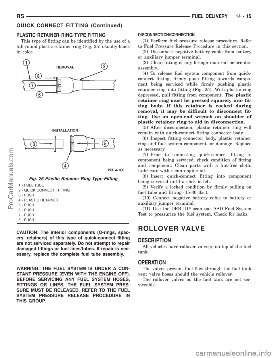
This type of fitting can be identified by the use of a
full-round plastic retainer ring (Fig. 25) usually black
in color.
CAUTION: The interior components (O-rings, spac-
ers, retainers) of this type of quick-connect fitting
are not serviced separately. Do not attempt to repair
damaged fittings or fuel lines/tubes. If repair is nec-
essary, replace the complete fuel tube assembly.
WARNING: THE FUEL SYSTEM IS UNDER A CON-
STANT PRESSURE (EVEN WITH THE ENGINE OFF).
BEFORE SERVICING ANY FUEL SYSTEM HOSES,
FITTINGS OR LINES, THE FUEL SYSTEM PRES-
SURE MUST BE RELEASED. REFER TO THE FUEL
SYSTEM PRESSURE RELEASE PROCEDURE IN
THIS GROUP.DISCONNECTION/CONNECTION
(1) Perform fuel pressure release procedure. Refer
to Fuel Pressure Release Procedure in this section.
(2) Disconnect negative battery cable from battery
or auxiliary jumper terminal.
(3) Clean fitting of any foreign material before dis-
assembly.
(4) To release fuel system component from quick-
connect fitting, firmly push fitting towards compo-
nent being serviced while firmly pushing plastic
retainer ring into fitting (Fig. 25). With plastic ring
depressed, pull fitting from component.The plastic
retainer ring must be pressed squarely into fit-
ting body. If this retainer is cocked during
removal, it may be difficult to disconnect fit-
ting. Use an open-end wrench on shoulder of
plastic retainer ring to aid in disconnection.
(5) After disconnection, plastic retainer ring will
remain with quick-connect fitting connector body.
(6) Inspect fitting connector body, plastic retainer
ring and fuel system component for damage. Replace
as necessary.
(7) Prior to connecting quick-connect fitting to
component being serviced, check condition of fitting
and component. Clean parts with a lint-free cloth.
Lubricate with clean engine oil.
(8) Insert quick-connect fitting into component
being serviced until a click is felt.
(9) Verify a locked condition by firmly pulling on
fuel tube and fitting (15-30 lbs.).
(10) Connect negative battery cable to battery or
auxiliary jumper terminal.
(11) Use the DRB IIItscan tool ASD Fuel System
Test to pressurize the fuel system. Check for leaks.
ROLLOVER VALVE
DESCRIPTION
All vehicles have rollover valve(s) on top of the fuel
tank.
OPERATION
The valves prevent fuel flow through the fuel tank
vent valve hoses should the vehicle rollover.
The rollover valves on the fuel tank are not ser-
viceable.
Fig. 25 Plastic Retainer Ring Type Fitting
1 - FUEL TUBE
2 - QUICK CONNECT FITTING
3 - PUSH
4 - PLASTIC RETAINER
5 - PUSH
6 - PUSH
7 - PUSH
8 - PUSH
RSFUEL DELIVERY14-15
QUICK CONNECT FITTING (Continued)
ProCarManuals.com