2001 DODGE TOWN AND COUNTRY air condition
[x] Cancel search: air conditionPage 479 of 2321
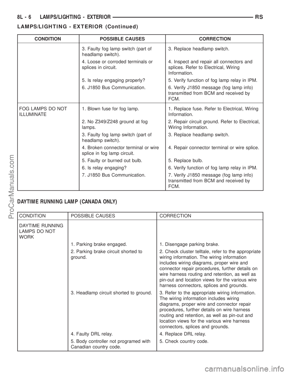
CONDITION POSSIBLE CAUSES CORRECTION
3. Faulty fog lamp switch (part of
headlamp switch).3. Replace headlamp switch.
4. Loose or corroded terminals or
splices in circuit.4. Inspect and repair all connectors and
splices. Refer to Electrical, Wiring
Information.
5. Is relay engaging properly? 5. Verify function of fog lamp relay in IPM.
6. J1850 Bus Communication. 6. Verify J1850 message (fog lamp info)
transmitted from BCM and received by
FCM.
FOG LAMPS DO NOT
ILLUMINATE1. Blown fuse for fog lamp. 1. Replace fuse. Refer to Electrical, Wiring
Information.
2. No Z349/Z248 ground at fog
lamps.2. Repair circuit ground. Refer to Electrical,
Wiring Information.
3. Faulty fog lamp switch (part of
headlamp switch).3. Replace headlamp switch.
4. Broken connector terminal or wire
splice in fog lamp circuit.4. Repair connector terminal or wire splice.
5. Faulty or burned out bulb. 5. Replace bulb.
6. Is relay engaging? 6. Verify function of fog lamp relay in IPM.
7. J1850 Bus Communication. 7. Verify J1850 message (fog lamp info)
transmitted from BCM and received by
FCM.
DAYTIME RUNNING LAMP (CANADA ONLY)
CONDITION POSSIBLE CAUSES CORRECTION
DAYTIME RUNNING
LAMPS DO NOT
WORK
1. Parking brake engaged. 1. Disengage parking brake.
2. Parking brake circuit shorted to
ground.2. Check cluster telltale, refer to the appropriate
wiring information. The wiring information
includes wiring diagrams, proper wire and
connector repair procedures, further details on
wire harness routing and retention, as well as
pin-out and location views for the various wire
harness connectors, splices and grounds.
3. Headlamp circuit shorted to ground. 3. Refer to the appropriate wiring information.
The wiring information includes wiring
diagrams, proper wire and connector repair
procedures, further details on wire harness
routing and retention, as well as pin-out and
location views for the various wire harness
connectors, splices and grounds.
4. Faulty DRL relay. 4. Replace DRL relay.
5. Body controller not programed with
Canadian country code.5. Check country code.
8L - 6 LAMPS/LIGHTING - EXTERIORRS
LAMPS/LIGHTING - EXTERIOR (Continued)
ProCarManuals.com
Page 497 of 2321
HEADLAMP LEVELING MOTOR
DIAGNOSIS AND TESTING - HEADLAMP
LEVELING MOTOR
HEADLAMP LEVELING MOTOR DIAGNOSIS
CONDITION POSSIBLE CAUSES CORRECTION
ONE MOTOR DOES NOT
OPERATE1. Poor electrical connection at
motor1. Check for proper electrical
connection at motor
2. No voltage at motor 2. Repair no voltage condition.
Refer to Wiring Diagrams
3. No ground at motor 3. Repair no ground condition.
Refer to Wiring Diagrams
4. Defective motor 4. Replace leveling motor
BOTH MOTORS DO NOT
OPERATE1. No voltage at or from headlamp
leveling switch1. Repair no voltage condition.
Check for proper headlamp
leveling switch operation
2. No voltage at leveling motors 2. Repair no voltage condition.
Refer to Wiring Diagrams
3. No ground at leveling motors 3. Repair no ground condition.
Refer to Wiring Diagrams
4. Both motors defective 4. Replace both motors
REMOVAL
(1) Disconnect and isolate the battery negative
cable.
(2) Remove headlamp unit.
(3) Disconnect electrical connector from headlamp
leveling motor.
(4) Remove the two mounting screws.
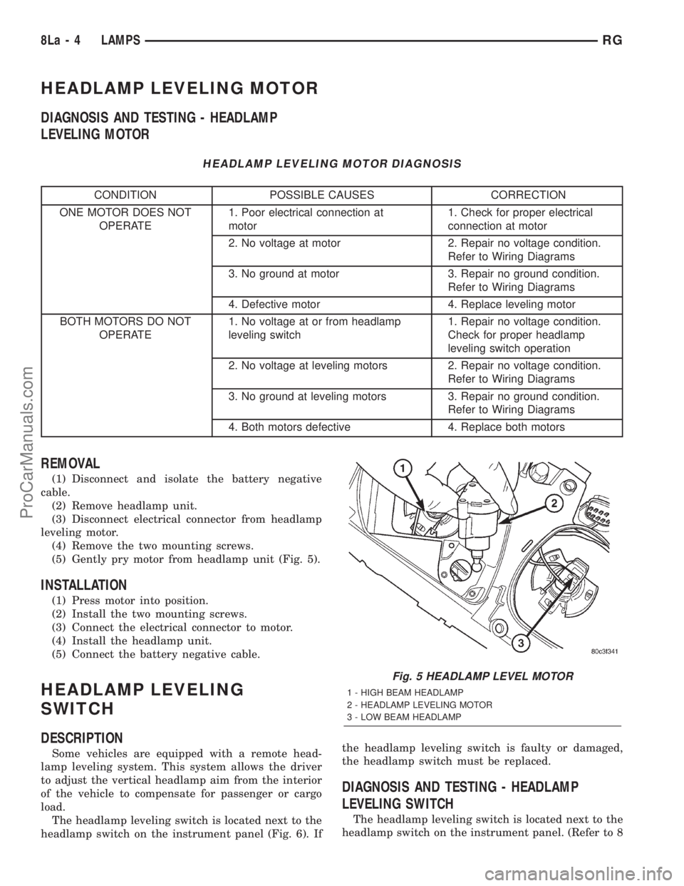
(5) Gently pry motor from headlamp unit (Fig. 5).
INSTALLATION
(1) Press motor into position.
(2) Install the two mounting screws.
(3) Connect the electrical connector to motor.
(4) Install the headlamp unit.
(5) Connect the battery negative cable.
HEADLAMP LEVELING
SWITCH
DESCRIPTION
Some vehicles are equipped with a remote head-
lamp leveling system. This system allows the driver
to adjust the vertical headlamp aim from the interior
of the vehicle to compensate for passenger or cargo
load.
The headlamp leveling switch is located next to the
headlamp switch on the instrument panel (Fig. 6). Ifthe headlamp leveling switch is faulty or damaged,
the headlamp switch must be replaced.
DIAGNOSIS AND TESTING - HEADLAMP
LEVELING SWITCH
The headlamp leveling switch is located next to the
headlamp switch on the instrument panel. (Refer to 8
Fig. 5 HEADLAMP LEVEL MOTOR
1 - HIGH BEAM HEADLAMP
2 - HEADLAMP LEVELING MOTOR
3 - LOW BEAM HEADLAMP
8La - 4 LAMPSRG
ProCarManuals.com
Page 503 of 2321
OVERHEAD CONSOLE
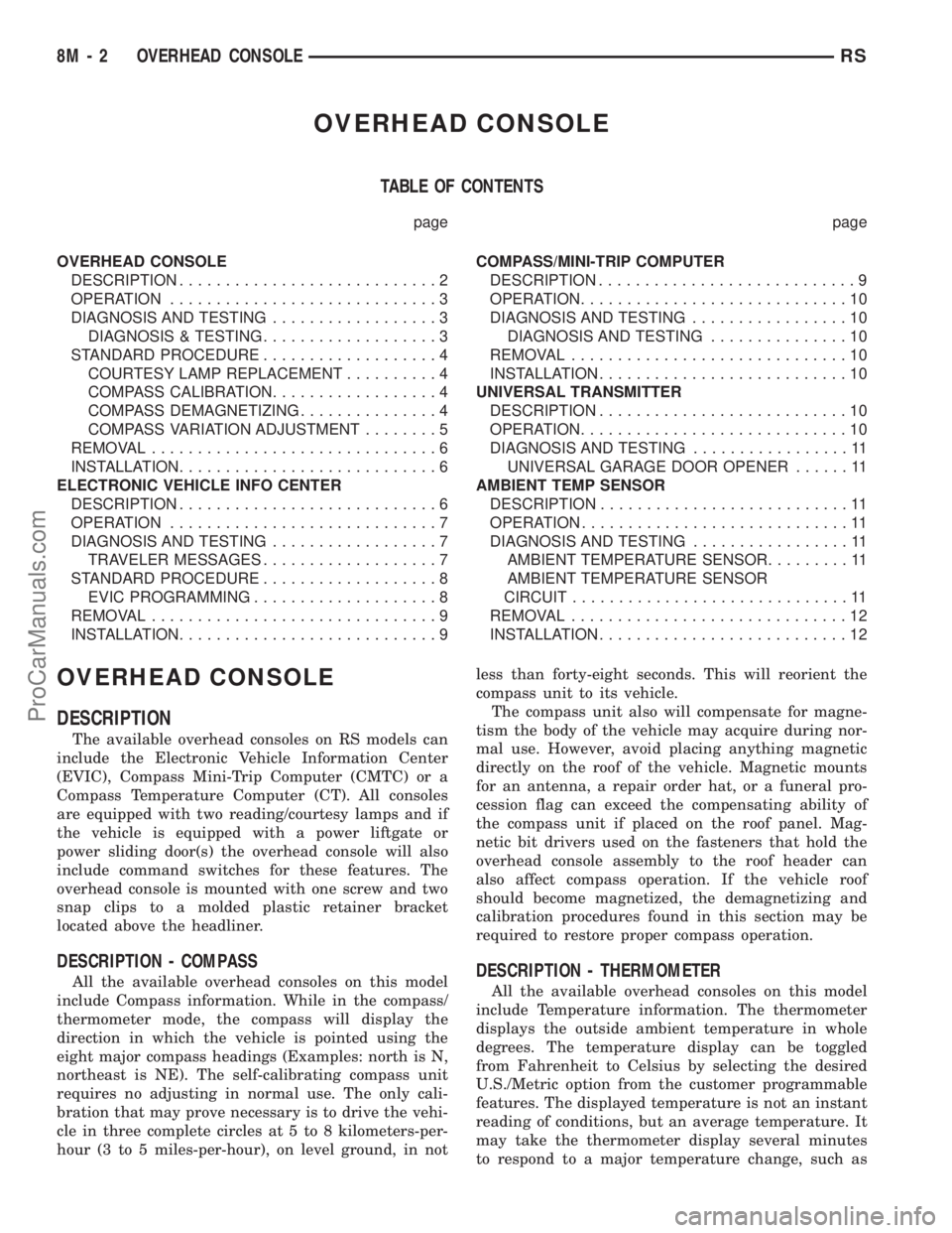
TABLE OF CONTENTS
page page
OVERHEAD CONSOLE
DESCRIPTION............................2
OPERATION.............................3
DIAGNOSIS AND TESTING..................3
DIAGNOSIS & TESTING...................3
STANDARD PROCEDURE...................4
COURTESY LAMP REPLACEMENT..........4
COMPASS CALIBRATION..................4
COMPASS DEMAGNETIZING...............4
COMPASS VARIATION ADJUSTMENT........5
REMOVAL...............................6
INSTALLATION............................6
ELECTRONIC VEHICLE INFO CENTER
DESCRIPTION............................6
OPERATION.............................7
DIAGNOSIS AND TESTING..................7
TRAVELER MESSAGES...................7
STANDARD PROCEDURE...................8
EVIC PROGRAMMING....................8
REMOVAL...............................9
INSTALLATION............................9COMPASS/MINI-TRIP COMPUTER
DESCRIPTION............................9
OPERATION.............................10
DIAGNOSIS AND TESTING.................10
DIAGNOSIS AND TESTING...............10
REMOVAL..............................10
INSTALLATION...........................10
UNIVERSAL TRANSMITTER
DESCRIPTION...........................10
OPERATION.............................10
DIAGNOSIS AND TESTING.................11
UNIVERSAL GARAGE DOOR OPENER......11
AMBIENT TEMP SENSOR
DESCRIPTION...........................11
OPERATION.............................11
DIAGNOSIS AND TESTING.................11
AMBIENT TEMPERATURE SENSOR.........11
AMBIENT TEMPERATURE SENSOR
CIRCUIT..............................11
REMOVAL..............................12
INSTALLATION...........................12
OVERHEAD CONSOLE
DESCRIPTION
The available overhead consoles on RS models can
include the Electronic Vehicle Information Center
(EVIC), Compass Mini-Trip Computer (CMTC) or a
Compass Temperature Computer (CT). All consoles
are equipped with two reading/courtesy lamps and if
the vehicle is equipped with a power liftgate or
power sliding door(s) the overhead console will also
include command switches for these features. The
overhead console is mounted with one screw and two
snap clips to a molded plastic retainer bracket
located above the headliner.
DESCRIPTION - COMPASS
All the available overhead consoles on this model
include Compass information. While in the compass/
thermometer mode, the compass will display the
direction in which the vehicle is pointed using the
eight major compass headings (Examples: north is N,
northeast is NE). The self-calibrating compass unit
requires no adjusting in normal use. The only cali-
bration that may prove necessary is to drive the vehi-
cle in three complete circles at 5 to 8 kilometers-per-
hour (3 to 5 miles-per-hour), on level ground, in notless than forty-eight seconds. This will reorient the
compass unit to its vehicle.
The compass unit also will compensate for magne-
tism the body of the vehicle may acquire during nor-
mal use. However, avoid placing anything magnetic
directly on the roof of the vehicle. Magnetic mounts
for an antenna, a repair order hat, or a funeral pro-
cession flag can exceed the compensating ability of
the compass unit if placed on the roof panel. Mag-
netic bit drivers used on the fasteners that hold the
overhead console assembly to the roof header can
also affect compass operation. If the vehicle roof
should become magnetized, the demagnetizing and
calibration procedures found in this section may be
required to restore proper compass operation.DESCRIPTION - THERMOMETER
All the available overhead consoles on this model
include Temperature information. The thermometer
displays the outside ambient temperature in whole
degrees. The temperature display can be toggled
from Fahrenheit to Celsius by selecting the desired
U.S./Metric option from the customer programmable
features. The displayed temperature is not an instant
reading of conditions, but an average temperature. It
may take the thermometer display several minutes
to respond to a major temperature change, such as
8M - 2 OVERHEAD CONSOLERS
ProCarManuals.com
Page 504 of 2321
driving out of a heated garage into winter tempera-
tures.
When the ignition switch is turned to the Off posi-
tion, the last displayed temperature reading stays in
the electronic control modules (CT, CMTC, EVIC)
memory. When the ignition switch is turned to the
On position again, the electronic module will display
the memory temperature for one minute; then update
the display to the current average temperature read-
ing within five minutes.
The thermometer function is supported by an
ambient temperature sensor. The sensor is mounted
outside the passenger compartment near the front
and center of the vehicle, and is hard wired to the
Front Control Module (FCM). The FCM sends tem-
perature status messages to the module over the
J1850 PCI data bus circuit.
Following are general descriptions of the major
components used in the overhead console. Refer to
Wiring Diagrams for complete circuit schematics.
OPERATION
Refer to the vehicle Owner's Manual for specific
operation of each overhead console and its systems.
DIAGNOSIS & TESTING - OVERHEAD
CONSOLE
If the problem with the overhead console is an
inaccurate or scrambled display, refer toSelf-Diag-
nostic Testlater in this group. If the problem with
the overhead console is incorrect Vacuum Fluorescent
Display (VFD) dimming levels, use a DRB IIItscan
tool and the proper Diagnostic Procedures manual to
test for the correct dimming message inputs being
received from the Body Control Module (BCM) or
Front Control Module (FCM) over the J1850 Pro-
grammable Communications Interface (PCI) data bus
circuit. If the problem is a no-display condition, use
the following procedures. For complete circuit dia-
grams, refer toOverhead Consolein the Wiring
Diagrams section of the service manual.
(1) Check the fused B(+) fuse in the intelligent
power module. If OK, go to Step 2. If not OK, repair
the shorted circuit or component as required and
replace the faulty fuse.
(2) Check for battery voltage at the fused B(+) fuse
in the intelligent power module. If OK, go to Step 3.
If not OK, repair the open fused B(+) circuit to the
fused B(+) fuse in the intelligent power module as
required.
(3) Check the fused ignition switch output (run/
start) fuse in the intelligent power module. If OK, go
to Step 4. If not OK, repair the shorted circuit or
component as required and replace the faulty fuse.
(4) Turn the ignition switch to the On position.
Check for battery voltage at the fused ignition switchoutput (run/start) fuse in the intelligent power mod-
ule. If OK, go to Step 5. If not OK, repair the open
fused ignition switch output (run/start) circuit to the
ignition switch as required.
(5) Turn the ignition switch to the Off position.
Disconnect and isolate the battery negative cable.
Remove the overhead console. Check for continuity
between the ground circuit cavity of the roof wire
harness connector for the electronics module and a
good ground. There should be continuity. If OK, go to
Step 6. If not OK, repair the open ground circuit to
ground as required.
(6) Connect the battery negative cable. Check for
battery voltage at the fused B(+) circuit cavity of the
roof wire harness connector for the electronics mod-
ule. If OK, go to Step 7. If not OK, repair the open
fused B(+) circuit to the fused B(+) fuse in the intel-
ligent power module as required.
(7) Turn the ignition switch to the On position.
Check for battery voltage at the fused ignition switch
output (run/start) circuit cavity of the roof wire har-
ness connector for the electronics module. If OK,
refer toSelf-Diagnostic Testlater this group for
further diagnosis of the electronics module and the
J1850 PCI data bus circuit. If not OK, repair the
open fused ignition switch output (run/start) circuit
to the fuse in the intelligent power module as
required.
SELF-DIAGNOSTIC TEST
A self-diagnostic test is used to determine that the
electronics module is operating properly, and that all
the J1850 PCI data bus messages are being received
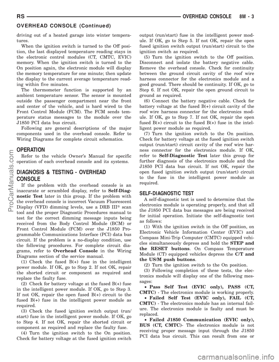
for initial operation. Initiate the self-diagnostic test
as follows:
(1) With the ignition switch in the Off position, on
Electronic Vehicle Information Center (EVIC) and
Compass Mini-Trip Computer (CMTC) equipped vehi-
cles simultaneously depress and hold theSTEP and
the RESET buttons. On Compass Temperature
Module (CT) equipped vehicles depress theC/T and
the US/M push buttons.
(2) Turn the ignition switch to the On position.
(3) Following completion of these tests, the elec-
tronics module will display one of the following mes-
sages:
²Pass Self Test (EVIC only), PASS (CT,
CMTC)- The electronics module is working properly.
²Failed Self Test (EVIC only), FAIL (CT,
CMTC)- The electronics module has an internal fail-
ure. The electronics module is faulty and must be
replaced.
²Failed J1850 Communication (EVIC only),
BUS (CT, CMTC)- The electronics module is not
receiving proper message input through the J1850
PCI data bus circuit. This can result from one or
RSOVERHEAD CONSOLE8M-3
OVERHEAD CONSOLE (Continued)
ProCarManuals.com
Page 554 of 2321
²UNLOCK: Pressing the UNLOCK button once
will unlock the driver's side doors and activate the
illuminated entry system and disarm Vehicle Theft
Security System, if equipped. Pressing the UNLOCK
button twice within five seconds will unlock all doors
and activate the illuminated entry system.
²LEFT SLIDING DOOR: Pressing the LEFT
SLIDING DOOR BUTTON opens/closes the left
power sliding door remotely.
²RIGHT SLIDING DOOR: Pressing the RIGHT
SLIDING DOOR BUTTON opens/closes the right
power sliding door remotely.
²LIFTGATE: Pressing the LIFTGATE BUTTON
opens/closes the liftgate remotely.
²PANIC: Pressing the PANIC button sounds the
horns at half second intervals, flashes the exterior
lamps, and turns ON the interior lamps. The panic
alarm will remain on for three minutes, or until the
PANIC button is actuated again or the ignition
switch is turned to the RUN position.
The Remote Keyless Entry Module is capable of
retaining the transmitter Vehicle Access Code(s)
(VAC) in its memory even after vehicle power has
been interrupted.
NOTE: Additional features available to the customer
are described in the Vehicle Owners Manual.
The RKE system activates the optional memory
seat and mirror system, if equipped. Two primary
key fob transmitters can be programmed to actuate
memory seat and mirror setting 1 or 2. Two addi-
tional key fob transmitters can be added, but they
will not be able to operate the memory seat and mir-
ror system (Refer to 8 - ELECTRICAL/POWER
SEATS - OPERATION) and (Refer to 8 - ELECTRI-
CAL/POWER MIRRORS - OPERATION).
DOOR LOCK MOTOR
DIAGNOSIS AND TESTING - DOOR LOCK
MOTOR
Verify battery condition before testing door lock
motor(s) (Refer to 8 - ELECTRICAL/BATTERY SYS-
TEM/BATTERY - DIAGNOSIS AND TESTING).
To determine which motor is faulty, check each
individual door for electrical lock and unlock or dis-
connect the motor connectors one at a time, while
operating the door lock switch. In the event that
none of the motors work, the problem may be caused
by a shorted motor or a bad switch. Disconnecting
the defective motor will allow the others to work.
To test an individual door lock motor, disconnect
the electrical connector from the motor. To lock the
door, connect a 12 volt power source to the positivepin of the lock motor and a ground wire to the other
pin. Refer to the appropriate wiring information. The
wiring information includes wiring diagrams, proper
wire and connector repair procedures, further details
on wire harness routing and retention, as well as
pin-out and location views for the various wire har-
ness connectors, splices and grounds. To unlock the
door reverse the wire connections at the motor pin
terminals. If these results are NOT obtained, replace
the motor.
DOOR LOCK SWITCH
DESCRIPTION
The Power Door Lock Switch is attached to the
door trim panel with two screws.
DIAGNOSIS AND TESTING - DOOR LOCK
SWITCH
(1) Remove door trim panel. Refer to Body, Door -
Front, Trim Panel, Removal and Installation.
(2) Disconnect wire connector from back of door
lock switch.
(3) Depress switch to LOCK position.
(4) Using an ohmmeter, test switch resistance
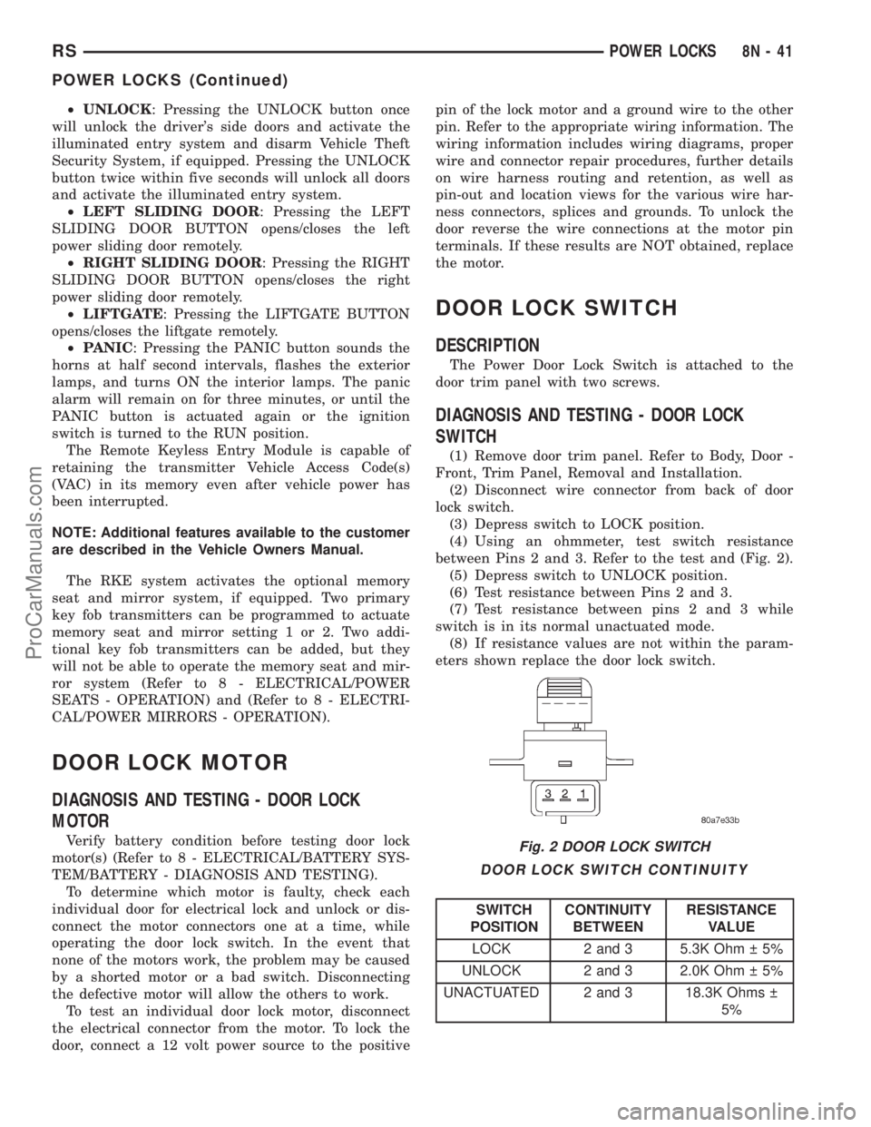
between Pins 2 and 3. Refer to the test and (Fig. 2).
(5) Depress switch to UNLOCK position.
(6) Test resistance between Pins 2 and 3.
(7) Test resistance between pins 2 and 3 while
switch is in its normal unactuated mode.
(8) If resistance values are not within the param-
eters shown replace the door lock switch.
DOOR LOCK SWITCH CONTINUITY
SWITCH
POSITIONCONTINUITY
BETWEENRESISTANCE
VALUE
LOCK 2 and 3 5.3K Ohm 5%
UNLOCK 2 and 3 2.0K Ohm 5%
UNACTUATED 2 and 3 18.3K Ohms
5%
Fig. 2 DOOR LOCK SWITCH
RSPOWER LOCKS8N-41
POWER LOCKS (Continued)
ProCarManuals.com
Page 582 of 2321
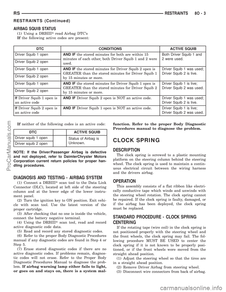
AIRBAG SQUIB STATUS
(1) Using a DRBIIItread Airbag DTC's
Ifthe following active codes are present:
DTC CONDITIONS ACTIVE SQUIB
Driver Squib 1 openAND IFthe stored minutes for both are within 15
minutes of each other, both Driver Squib 1 and 2 were
used.Both Driver Squib 1 and
2 were used.
Driver Squib 2 open
Driver Squib 1 openAND IFthe stored minutes for Driver Squib 2 open is
GREATER than the stored minutes for Driver Squib 1
by 15 minutes or more.Driver Squib 1 was used;
Driver Squib 2 is live.
Driver Squib 2 open
Driver Squib 1 openAND IFthe stored minutes for Driver Squib 1 open is
GREATER than the stored minutes for Driver Squib 2
by 15 minutes or more.Driver Squib 1 is live;
Driver Squib 2 was used.
Driver Squib 2 open
IfDriver Squib 1 open is
an active codeAND IFDriver Squib 2 open is NOT an active code.Driver Squib 1 was used;
Driver Squib 2 is live.
IfDriver Squib 2 open is
an active codeAND IFDriver Squib 1 open is NOT an active code.Driver Squib 1 is live;
Driver Squib 2 was used.
Ifneither of the following codes is an active code:
DTC ACTIVE SQUIB
Driver squib 1 open
Status of Airbag is
Unknown.
Driver squib 2 open
NOTE: If the Driver/Passenger Airbag is defective
and not deployed, refer to DaimlerChrysler Motors
Corporation current return policies for proper han-
dling procedures.
DIAGNOSIS AND TESTING - AIRBAG SYSTEM
(1) Connect a DRBIIItscan tool to the Data Link
Connector (DLC), located at left side of the steering
column and at the lower edge of the lower instru-
ment panel.
(2) Turn the ignition key to ON position. Exit vehi-
cle with scan tool. Use the latest version of the
proper cartridge.
(3) After checking that no one is inside the vehicle,
connect the battery negative terminal.
(4) Using the DRBIIItscan tool, read and record
active diagnostic code data.
(5) Read and record any stored diagnostic codes.
(6) Refer to the proper Body Diagnostic Procedures
manual if any diagnostic codes are found in Step 4 or
Step 5.
(7) Erase stored diagnostic codes if there are no
active diagnostic codes. If problems remain, diagnos-
tic codes will not erase. Refer to the Proper Body
Diagnostic Procedures Manual to diagnose the prob-
lem.If airbag warning lamp either fails to light,
or goes on and stays on, there is a system mal-function. Refer to the proper Body Diagnostic
Procedures manual to diagnose the problem.
CLOCK SPRING
DESCRIPTION
The clock spring is screwed to a plastic mounting
platform on the steering column behind the steering
wheel. The clock spring is used to maintain a contin-
uous electrical circuit between the wiring harness
and the drivers airbag.
OPERATION
This assembly consists of a flat ribbon like electri-
cally conductive tape which winds and unwinds with
the steering wheel rotation. The clock spring cannot
be repaired. If the clock spring is faulty, damaged, or
if the airbag has been deployed, the clock spring
must be replaced.
STANDARD PROCEDURE - CLOCK SPRING
CENTERING
If the rotating tape (wire coil) in the clock spring is
not positioned properly with the steering wheel and
the front wheels, the clock spring may fail. The fol-
lowing procedure MUST BE USED to center the
clock spring if it is not known to be properly posi-
tioned, or if the front wheels were moved from the
straight ahead position.
(1) Adjust the steering wheel so that the tires are
in a straight ahead position.
(2) Remove Driver Airbag from steering wheel.
(3) Disconnect wire connectors from back of airbag.
RSRESTRAINTS8O-3
RESTRAINTS (Continued)
ProCarManuals.com
Page 586 of 2321
REMOVAL
DEPLOYED AIRBAG
(1) Clean powder residue from interior of vehicle.
Refer to Electrical, Restraints, Passenger Airbag,
Standard Procedure - Passenger Airbag Clean Up.
(2) Remove instrument panel. Refer to Body,
Instrument Panel, Removal.
(3) Remove all reusable components from the
upper instrument panel and transfer to the new
instrument panel.
UNDEPLOYED AIRBAG
(1) Remove instrument panel. Refer to Body,
Instrument Panel, Removal.
(2) De-trim the instrument panel enough to gain
access to the passenger airbag fasteners.
(3) Disconnect yellow wire connector from passen-
ger airbag.
(4) Remove three bolts to the passenger airbag.
(5) Remove airbag from instrument panel through
rear of instrument panel.
INSTALLATION
DEPLOYED AIRBAG
Transfer all reusable components to the new
instrument panel.
(1) Install new Passenger Airbag into instrument
panel.
(2) Install airbag attaching bolts to the instrument
panel.
(3) Connect yellow wire connector from passenger
airbag.
(4) Install Instrument panel. Refer to Body, Instru-
ment Panel, Installation.
WARNING: DO NOT CONNECT THE BATTERY NEG-
ATIVE CABLE. REFER TO ELECTRICAL,
RESTRAINTS, DIAGNOSIS AND TESTING - AIRBAG
SYSTEM FIRST.
UNDEPLOYED AIRBAG
(1) Install Passenger Airbag into instrument panel.
(2) Install airbag attaching bolts to the instrument
panel.
(3) Connect yellow wire connector from passenger
airbag.
(4) Install Instrument panel. Refer to Body, Instru-
ment Panel, Installation.
WARNING: DO NOT CONNECT THE BATTERY NEG-
ATIVE CABLE. REFER TO ELECTRICAL,
RESTRAINTS, DIAGNOSIS AND TESTING - AIRBAG
SYSTEM FIRST.
SEAT AIRBAG
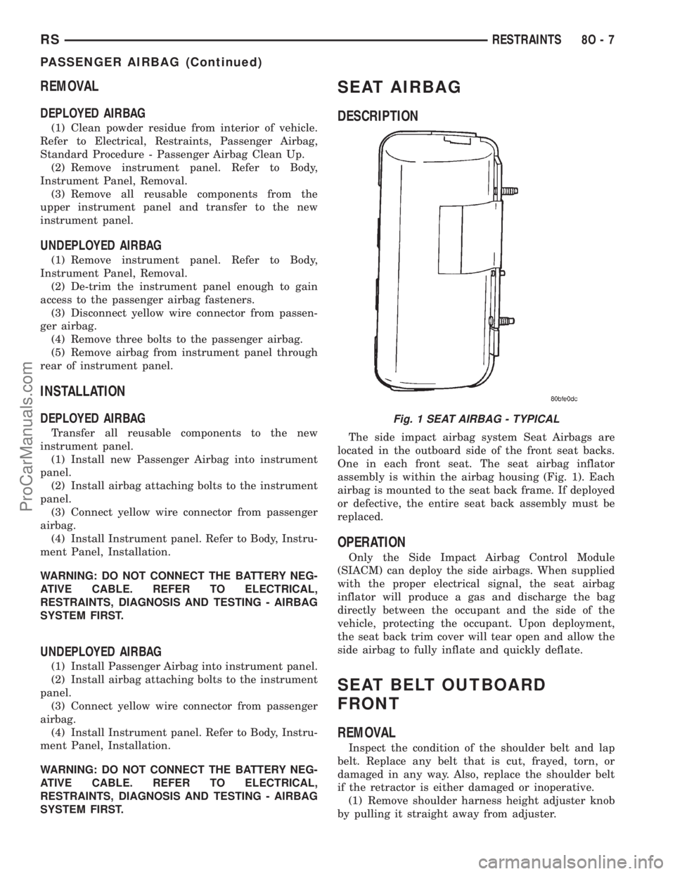
DESCRIPTION
The side impact airbag system Seat Airbags are
located in the outboard side of the front seat backs.
One in each front seat. The seat airbag inflator
assembly is within the airbag housing (Fig. 1). Each
airbag is mounted to the seat back frame. If deployed
or defective, the entire seat back assembly must be
replaced.
OPERATION
Only the Side Impact Airbag Control Module
(SIACM) can deploy the side airbags. When supplied
with the proper electrical signal, the seat airbag
inflator will produce a gas and discharge the bag
directly between the occupant and the side of the
vehicle, protecting the occupant. Upon deployment,
the seat back trim cover will tear open and allow the
side airbag to fully inflate and quickly deflate.
SEAT BELT OUTBOARD
FRONT
REMOVAL
Inspect the condition of the shoulder belt and lap
belt. Replace any belt that is cut, frayed, torn, or
damaged in any way. Also, replace the shoulder belt
if the retractor is either damaged or inoperative.
(1) Remove shoulder harness height adjuster knob
by pulling it straight away from adjuster.
Fig. 1 SEAT AIRBAG - TYPICAL
RSRESTRAINTS8O-7
PASSENGER AIRBAG (Continued)
ProCarManuals.com
Page 596 of 2321
SPEED CONTROL
TABLE OF CONTENTS
page page
SPEED CONTROL
DESCRIPTION............................1
OPERATION.............................1
DIAGNOSIS AND TESTING..................3
ROAD TEST............................3
SPECIFICATIONS.........................3
CABLE
DESCRIPTION............................3
OPERATION.............................3
REMOVAL...............................3
INSTALLATION............................4
SERVO
DESCRIPTION............................4OPERATION.............................4
REMOVAL...............................4
INSTALLATION............................4
SWITCH
DESCRIPTION............................5
OPERATION.............................5
REMOVAL...............................5
INSTALLATION............................5
VACUUM RESERVOIR
DESCRIPTION............................6
OPERATION.............................6
REMOVAL...............................6
INSTALLATION............................6
SPEED CONTROL
DESCRIPTION
The speed control system is electronically con-
trolled and vacuum operated. The electronic control
is integrated into the powertrain control module,
located on the driver's side under the speed control
servo. The controls are located on the steering wheel.
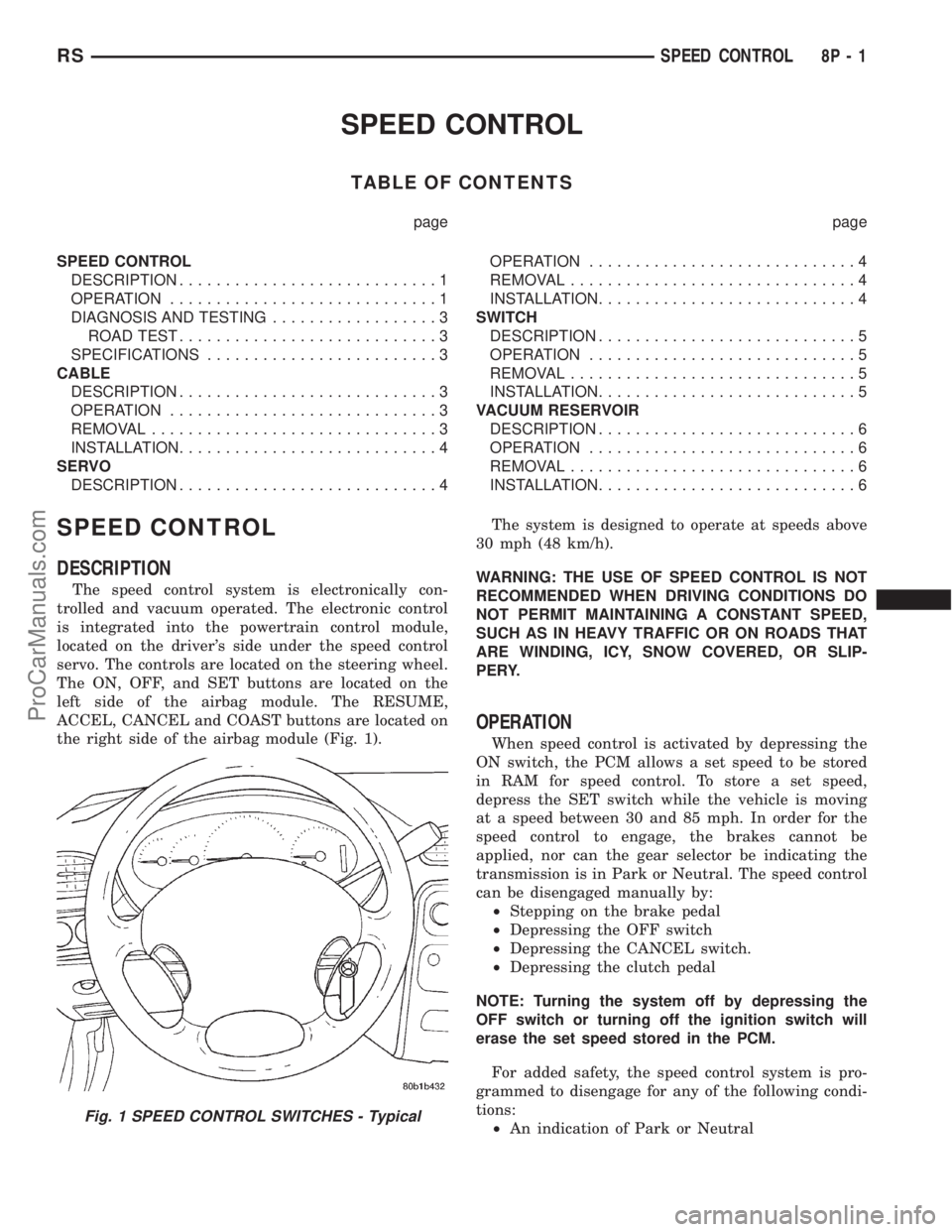
The ON, OFF, and SET buttons are located on the
left side of the airbag module. The RESUME,
ACCEL, CANCEL and COAST buttons are located on
the right side of the airbag module (Fig. 1).The system is designed to operate at speeds above
30 mph (48 km/h).
WARNING: THE USE OF SPEED CONTROL IS NOT
RECOMMENDED WHEN DRIVING CONDITIONS DO
NOT PERMIT MAINTAINING A CONSTANT SPEED,
SUCH AS IN HEAVY TRAFFIC OR ON ROADS THAT
ARE WINDING, ICY, SNOW COVERED, OR SLIP-
PERY.
OPERATION
When speed control is activated by depressing the
ON switch, the PCM allows a set speed to be stored
in RAM for speed control. To store a set speed,
depress the SET switch while the vehicle is moving
at a speed between 30 and 85 mph. In order for the
speed control to engage, the brakes cannot be
applied, nor can the gear selector be indicating the
transmission is in Park or Neutral. The speed control
can be disengaged manually by:
²Stepping on the brake pedal
²Depressing the OFF switch
²Depressing the CANCEL switch.
²Depressing the clutch pedal
NOTE: Turning the system off by depressing the
OFF switch or turning off the ignition switch will
erase the set speed stored in the PCM.
For added safety, the speed control system is pro-
grammed to disengage for any of the following condi-
tions:
²An indication of Park or Neutral
Fig. 1 SPEED CONTROL SWITCHES - Typical
RSSPEED CONTROL8P-1
ProCarManuals.com