2001 DODGE TOWN AND COUNTRY air condition
[x] Cancel search: air conditionPage 600 of 2321
(4) Connect vacuum line to speed control servo
that leads to the battery tray/vacuum reservoir.
(5) Install speed control servo and bracket.
(6) Install battery tray/vacuum reservoir, refer to
the Battery section for more information.
(7) Install speed control and throttle cable casing
to cable mount bracket.
(8) Connect the throttle and speed control cable
ends to throttle body.
(9) Connect the negative battery cable.
SWITCH
DESCRIPTION
There are two separate switch pods that operate
the speed control system and are located on the
steering wheel.
OPERATION
The speed control system has five separate resis-
tive switches that provide a single multiplexed
(MUX) voltage inputs to the PCM.The switch names
are: ON, OFF, SET, COAST, RESUME, ACCEL, TAP-
UP, COAST, and CANCEL. Based on conditions when
the buttons are pushed (and released), the five volt-
ages ranges provided to the PCM result in the follow-
ing functions: ON, OFF, SET, COAST, RESUME,
ACCEL, TAP-UP, COAST, and CANCEL. Refer to the
Speed Control Section for more information
Also the PCM receives an input from the brake
switch to sense whether the brake pedal has been
depressed. When the PCM receives the brake
depressed input, it turns off power to the speed con-
trol servo and disengages speed control.
The individual switches cannot be repaired. If one
switch fails, the entire switch module must be
replaced.
REMOVAL
The speed control switches are mounted in the
steering wheel and wired through the clock spring
device under the airbag module.
WARNING: IF REMOVAL OF AIRBAG MODULE IS
NECESSARY, REFER TO THE RESTRAINT SYS-
TEMS SECTION FOR MORE INFORMATION.
(1) Remove the negative battery cable.
(2) Turn off ignition.
(3) Remove the air bag, refer to the restraint sec-
tion for more information.
(4) Remove two screws from side of the switch.
(5) Remove switch from steering wheel.
(6) Disconnect two-way electrical connector.
(7) Repeat for the other switch.
INSTALLATION
The speed control switches are mounted in the
steering wheel and wired through the clock spring
device under the airbag module.
WARNING: IF REMOVAL OF AIRBAG MODULE IS
NECESSARY, REFER TO THE RESTRAINT SYS-
TEMS SECTION FOR MORE INFORMATION.
(1) Connect two-way electrical connector.
(2) Install switch.
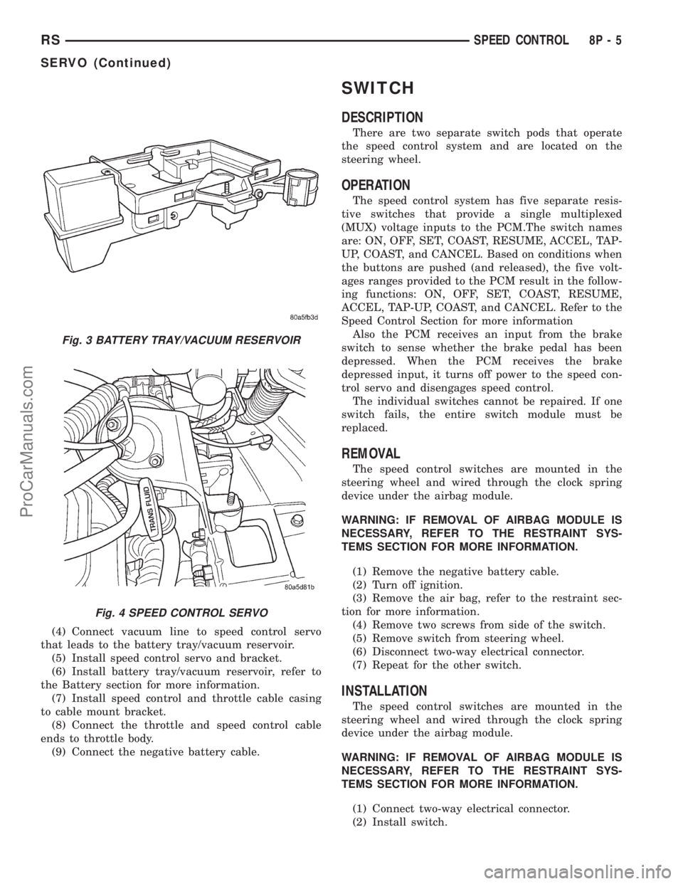
Fig. 3 BATTERY TRAY/VACUUM RESERVOIR
Fig. 4 SPEED CONTROL SERVO
RSSPEED CONTROL8P-5
SERVO (Continued)
ProCarManuals.com
Page 603 of 2321
NOTE: The VTSS will not arm by pushing down the
door lock mechanism. This will manually override
the system.
For Door Cylinder Lock Switch Removal and
Installation, refer to Electrical, Power Locks, Door
Cylinder Lock Switch.
If the VTSS is triggered, the horn will pulse, head-
lamps/marker lamps will flash, and the VTSS warn-
ing lamp will flash. If BCM determines the threat to
be false and the VTSS is not triggered again, the sys-
tem will shut down and rearm itself after three min-
utes. If a trigger is still active, the alarm will
continue for an additional 15 minutes without the
horn. The VTSS monitoring portion of the system is
split into two sections. The engine compartment sec-
tion and the passenger compartment section. If a
malfunction occurs in the engine compartment sec-
tion, the passenger compartment section would still
arm and function normally.
NOTE: If hood is not secure during the arming
sequence, the lamp will stay lit and not flash. The
system will arm with hood not secured (hood ajar
switch closed) and the liftgate open (liftgate ajar
switch closed). System will not arm if passenger
compartment is not secure (all switches closed)
ARMING THE VTSS - METHOD A
(1) With the key removed from the ignition lock
and any door open (excluding liftgate), actuate one of
the following:
²Power door lock button to LOCK,
²Key fob LOCK button
²Door lock key cylinder to locked position.
(2) Close all opened doors. Liftgate can remain
open.
(3) After the last door is closed, an arming time-
out period of sixteen seconds will start, then the
VTSS will become armed.
ARMING THE VTSS - METHOD B
Actuating the key fob transmitter LOCK button,
key locking the front doors or liftgate with the doors
closed and the ignition locked will begin the arming
time-out period. If method A, 16 second time-out
sequence was in process when method B was actu-
ated, the 16 second time-out will restart from the
time of the second actuation.
If the security lamp does not illuminate at all upon
final door closure, it indicates that the system is not
arming.
The current VTSS status armed or disarmed shall
be maintained in memory to prevent battery discon-
nects from disarming the system.
TRIGGERING THE VTSS
After the VTSS is armed, the following actions will
trigger the alarm:
²Opening any door.
²Opening the hood
²Turning the ignition to the ON, ACC, or
UNLOCK position.
²Opening liftgate without first receiving a RKE
input or liftgate key input.
CAUTION: The VTSS indicator LED will trigger and
engine will continue to run if the vehicle is
equipped with SKIS and the proper key is used to
start the vehicle. This condition will occur if the
VTSS has been triggered. If valid key is used, VTSS
will disarm
SENTRY KEY IMMOBILIZER SYSTEM
The SKIS includes keys from the factory which are
pre-programmed. Each SKIM will recognize a maxi-
mum of eight Sentry Keys. If the customer would
like to own additional keys other than those provided
with the vehicle, they can be purchased from any
authorized dealer. These keys must be programmed
to the SKIM on the vehicle in order for the system to
recognize them as valid keys. This can be done by
the dealer with a DRB IIItscan tool or by a cus-
tomer if this feature is available in their market and
they have two (2) valid keys already available to
them. Refer to the Service Procedures portion of this
system for additional details. The SKIS performs a
self-test each time the ignition switch is turned to
the ON position and will store Diagnostic Trouble
Codes (DTC's) if a system malfunction is detected.
The SKIS can be diagnosed and any stored DTC's
can be retrieved using a DRB IIItscan tool as
described in the appropriate Body Diagnostic Proce-
dures manual.
DIAGNOSIS AND TESTING - SENTRY KEY
IMMOBILIZER SYSTEM
WARNING: ON VEHICLES EQUIPPED WITH AIR-
BAGS, REFER TO ELECTRICAL, RESTRAINTS,
WARNINGS, BEFORE ATTEMPTING COMPONENT
DIAGNOSIS OR SERVICE. FAILURE TO TAKE THE
PROPER PRECAUTIONS COULD RESULT IN ACCI-
DENTAL AIRBAG DEPLOYMENT AND POSSIBLE
PERSONAL INJURY.
8Q - 2 VEHICLE THEFT SECURITYRS
VEHICLE THEFT SECURITY (Continued)
ProCarManuals.com
Page 611 of 2321
CONDITION POSSIBLE CAUSES CORRECTION
WIPER MOTOR WILL NOT
RUN1. BLOWN FUSE.
2. NEW FUSE BLOWS.
3. NEW FUSE BLOWS.
4. NO VOLTAGE AT MOTOR.
5. POOR GROUND.1. REPLACE FUSE, AND RUN SYSTEM.
2. CHECK FOR SHORT IN WIRING OR
SWITCH.
3. REPLACE FUSE, REMOVE MOTOR
CONNECTOR, TURN SWITCH ON, FUSE
DOES NOT BLOW, REPLACE MOTOR.
4. CHECK SWITCH AND WIRING
HARNESS. REFER TO WIRING
DIAGRAMS.
5. REPAIR GROUND WIRE CONNECTION
AS NECESSARY.
FRONT WIPER ARMS
REMOVAL
CAUTION: The driver side wiper arm must be
parked above the passenger side. Failure to do so
will result in damage to the arms, blades or system.
(1) Disengage the clip holding outside end of the
wiper arm pivot cover to the wiper arm.
(2) Lift the arm cap upward.
(3) Remove the nut holding wiper arm to the wiper
pivot.
(4) Using a suitable two jaw puller, separate the
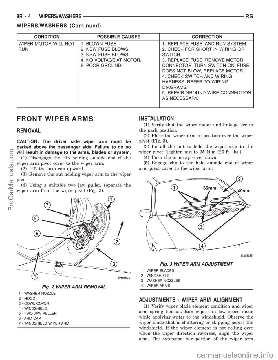
wiper arm from the wiper pivot (Fig. 2).
INSTALLATION
(1) Verify that the wiper motor and linkage are in
the park position.
(2) Place the wiper arm in position over the wiper
pivot (Fig. 3).
(3) Install the nut to hold the wiper arm to the
wiper pivot. Tighten nut to 35 N´m (26 ft. lbs.).
(4) Push the arm cap cover down.
(5) Engage clip to the hold outside end of wiper
arm pivot cover to the wiper arm.
ADJUSTMENTS - WIPER ARM ALIGNMENT
(1) Verify wiper blade element condition and wiper
arm spring tension. Run wipers in low speed mode
while applying water to the windshield. Observe the
wiper blade that is chattering or skipping across the
windshield. If the wiper element is not rolling over
when the wiper direction reverses, align the wiper
arm. The extension bar portion of the wiper arm
Fig. 2 WIPER ARM REMOVAL
1 - WASHER NOZZLE
2 - HOOD
3 - COWL COVER
4 - WINDSHIELD
5 - TWO JAW PULLER
6 - ARM CAP
7 - WINDSHIELD WIPER ARM
Fig. 3 WIPER ARM ADJUSTMENT
1 - WIPER BLADES
2 - WINDSHIELD
3 - WASHER NOZZLES
4 - WIPER ARMS
8R - 4 WIPERS/WASHERSRS
WIPERS/WASHERS (Continued)
ProCarManuals.com
Page 618 of 2321
WIRING
TABLE OF CONTENTS
page page
WIRING DIAGRAM INFORMATION...... 8Wa-01-1
COMPONENT INDEX................. 8Wa-02-1
POWER DISTRIBUTION.............. 8Wa-10-1
GROUND DISTRIBUTION............. 8Wa-15-1
BUS COMMUNICATIONS............. 8Wa-18-1
CHARGING SYSTEM................. 8Wa-20-1
STARTING SYSTEM................. 8Wa-21-1
FUEL/IGNITION SYSTEM............. 8Wa-30-1
TRANSMISSION CONTROL SYSTEM.... 8Wa-31-1
VEHICLE SPEED CONTROL........... 8Wa-33-1
ANTILOCK BRAKES.................. 8Wa-35-1
VEHICLE THEFT SECURITY SYSTEM.... 8Wa-39-1
INSTRUMENT CLUSTER.............. 8Wa-40-1
HORN/CIGAR LIGHTER/POWER OUTLET . 8Wa-41-1
AIR CONDITIONING-HEATER.......... 8Wa-42-1
AIRBAG SYSTEM................... 8Wa-43-1
INTERIOR LIGHTING................. 8Wa-44-1
BODY CONTROL MODULE............ 8Wa-45-1MESSAGE CENTER.................. 8Wa-46-1
AUDIO SYSTEM.................... 8Wa-47-1
REAR WINDOW DEFOGGER........... 8Wa-48-1
OVERHEAD CONSOLE................ 8Wa-49-1
FRONT LIGHTING................... 8Wa-50-1
REAR LIGHTING.................... 8Wa-51-1
TURN SIGNALS..................... 8Wa-52-1
WIPERS........................... 8Wa-53-1
TRAILER TOW...................... 8Wa-54-1
POWER WINDOWS.................. 8Wa-60-1
POWER DOOR LOCKS............... 8Wa-61-1
POWER MIRRORS.................. 8Wa-62-1
POWER SEATS..................... 8Wa-63-1
SPLICE INFORMATION............... 8Wa-70-1
CONNECTOR PIN-OUTS.............. 8Wa-80-1
CONNECTOR/GROUND LOCATIONS BUX . 8Wa-90-1
SPLICE LOCATIONS BUX............. 8Wa-95-1 RGWIRING
8Wa-1
ProCarManuals.com
Page 818 of 2321
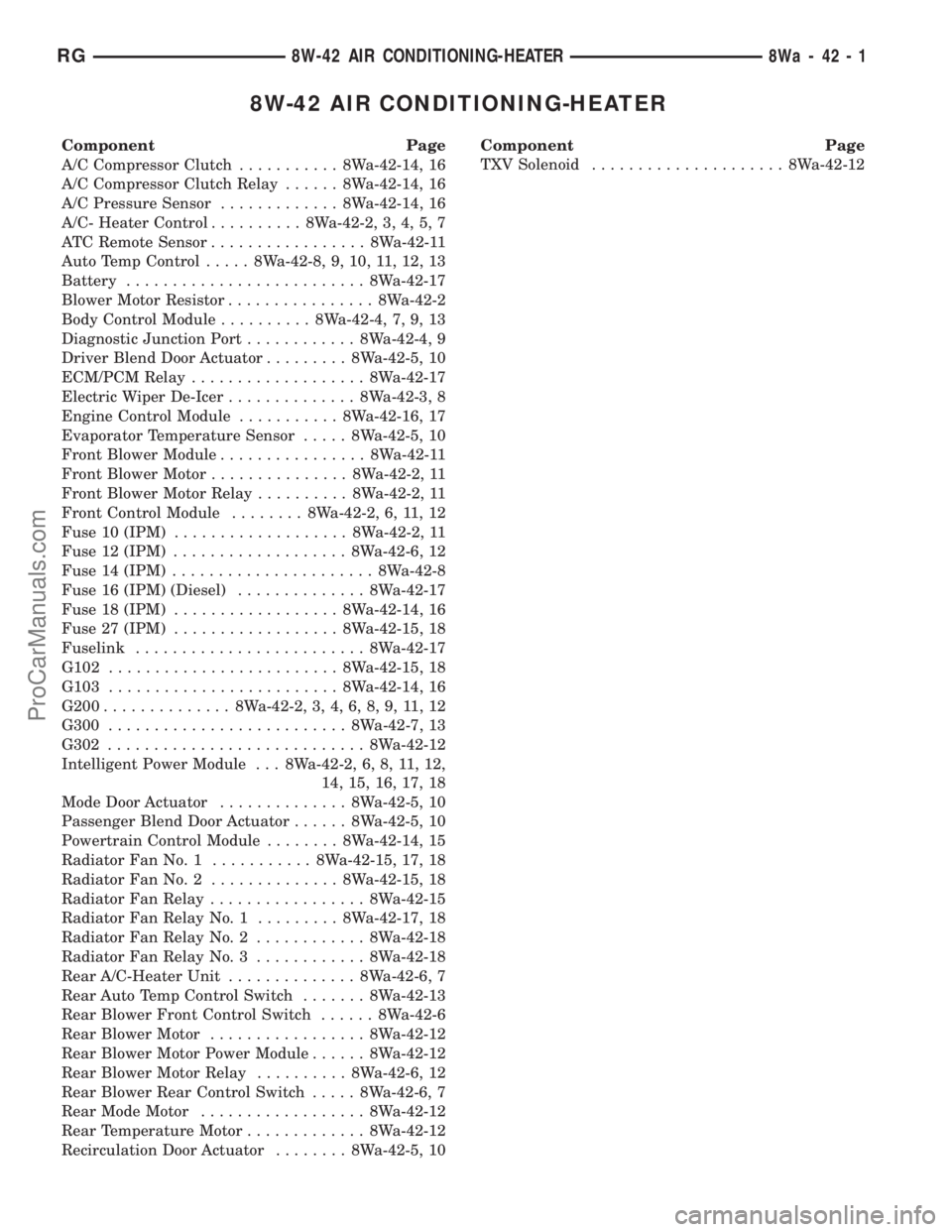
8W-42 AIR CONDITIONING-HEATER
Component Page
A/C Compressor Clutch........... 8Wa-42-14, 16
A/C Compressor Clutch Relay...... 8Wa-42-14, 16
A/C Pressure Sensor............. 8Wa-42-14, 16
A/C- Heater Control.......... 8Wa-42-2, 3, 4, 5, 7
ATC Remote Sensor................. 8Wa-42-11
Auto Temp Control..... 8Wa-42-8, 9, 10, 11, 12, 13
Battery.......................... 8Wa-42-17
Blower Motor Resistor................ 8Wa-42-2
Body Control Module.......... 8Wa-42-4, 7, 9, 13
Diagnostic Junction Port............ 8Wa-42-4, 9
Driver Blend Door Actuator......... 8Wa-42-5, 10
ECM/PCM Relay................... 8Wa-42-17
Electric Wiper De-Icer.............. 8Wa-42-3, 8
Engine Control Module........... 8Wa-42-16, 17
Evaporator Temperature Sensor..... 8Wa-42-5, 10
Front Blower Module................ 8Wa-42-11
Front Blower Motor............... 8Wa-42-2, 11
Front Blower Motor Relay.......... 8Wa-42-2, 11
Front Control Module........ 8Wa-42-2, 6, 11, 12
Fuse 10 (IPM)................... 8Wa-42-2, 11
Fuse 12 (IPM)................... 8Wa-42-6, 12
Fuse 14 (IPM)...................... 8Wa-42-8
Fuse 16 (IPM) (Diesel).............. 8Wa-42-17
Fuse 18 (IPM).................. 8Wa-42-14, 16
Fuse 27 (IPM).................. 8Wa-42-15, 18
Fuselink......................... 8Wa-42-17
G102......................... 8Wa-42-15, 18
G103......................... 8Wa-42-14, 16
G200.............. 8Wa-42-2, 3, 4, 6, 8, 9, 11, 12
G300.......................... 8Wa-42-7, 13
G302............................ 8Wa-42-12
Intelligent Power Module . . . 8Wa-42-2, 6, 8, 11, 12,
14, 15, 16, 17, 18
Mode Door Actuator.............. 8Wa-42-5, 10
Passenger Blend Door Actuator...... 8Wa-42-5, 10
Powertrain Control Module........ 8Wa-42-14, 15
Radiator Fan No. 1........... 8Wa-42-15, 17, 18
Radiator Fan No. 2.............. 8Wa-42-15, 18
Radiator Fan Relay................. 8Wa-42-15
Radiator Fan Relay No. 1......... 8Wa-42-17, 18
Radiator Fan Relay No. 2............ 8Wa-42-18
Radiator Fan Relay No. 3............ 8Wa-42-18
Rear A/C-Heater Unit.............. 8Wa-42-6, 7
Rear Auto Temp Control Switch....... 8Wa-42-13
Rear Blower Front Control Switch...... 8Wa-42-6
Rear Blower Motor................. 8Wa-42-12
Rear Blower Motor Power Module...... 8Wa-42-12
Rear Blower Motor Relay.......... 8Wa-42-6, 12
Rear Blower Rear Control Switch..... 8Wa-42-6, 7
Rear Mode Motor.................. 8Wa-42-12
Rear Temperature Motor............. 8Wa-42-12
Recirculation Door Actuator........ 8Wa-42-5, 10Component Page
TXV Solenoid..................... 8Wa-42-12
RG8W-42 AIR CONDITIONING-HEATER8Wa-42-1
ProCarManuals.com
Page 1160 of 2321
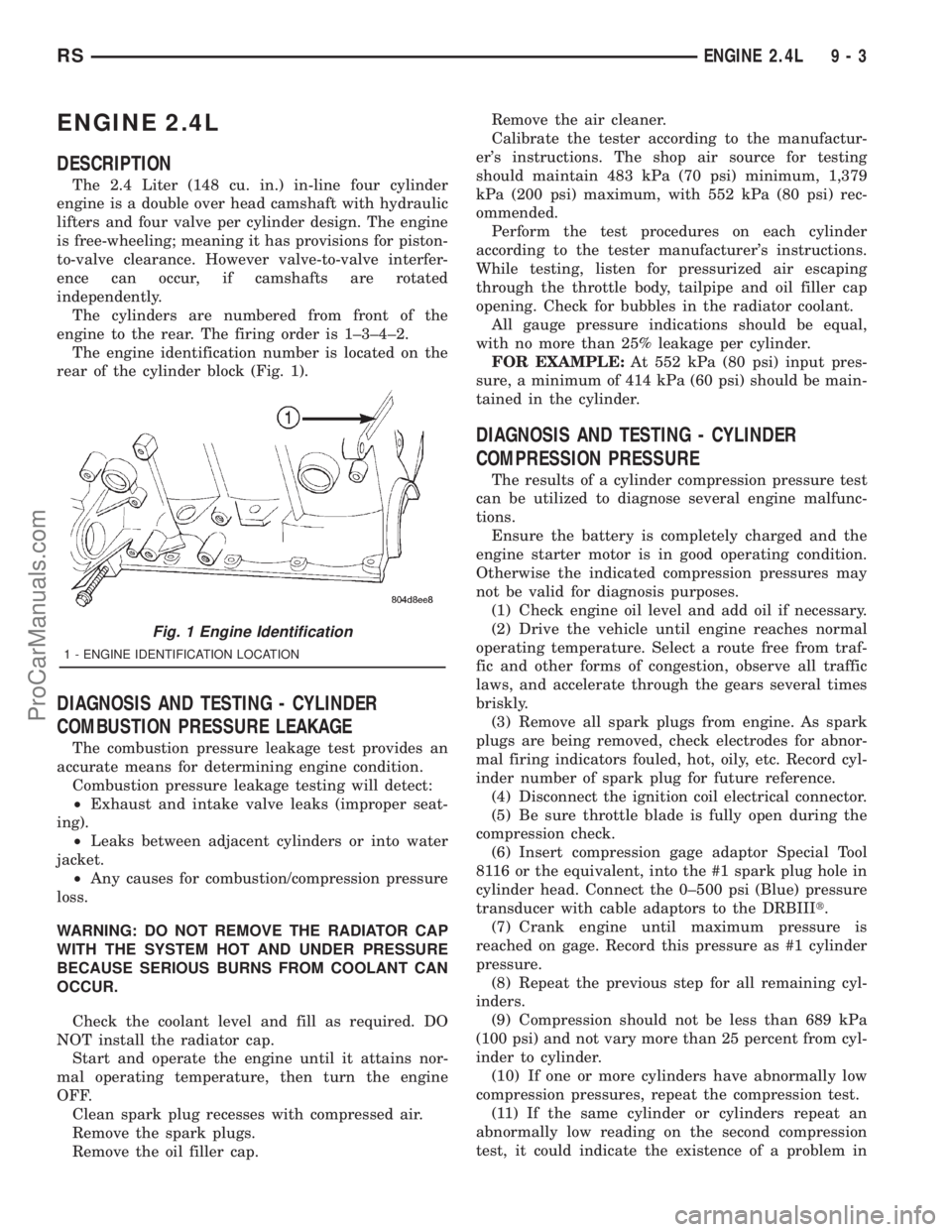
ENGINE 2.4L
DESCRIPTION
The 2.4 Liter (148 cu. in.) in-line four cylinder
engine is a double over head camshaft with hydraulic
lifters and four valve per cylinder design. The engine
is free-wheeling; meaning it has provisions for piston-
to-valve clearance. However valve-to-valve interfer-
ence can occur, if camshafts are rotated
independently.
The cylinders are numbered from front of the
engine to the rear. The firing order is 1±3±4±2.
The engine identification number is located on the
rear of the cylinder block (Fig. 1).
DIAGNOSIS AND TESTING - CYLINDER
COMBUSTION PRESSURE LEAKAGE
The combustion pressure leakage test provides an
accurate means for determining engine condition.
Combustion pressure leakage testing will detect:
²Exhaust and intake valve leaks (improper seat-
ing).
²Leaks between adjacent cylinders or into water
jacket.
²Any causes for combustion/compression pressure
loss.
WARNING: DO NOT REMOVE THE RADIATOR CAP
WITH THE SYSTEM HOT AND UNDER PRESSURE
BECAUSE SERIOUS BURNS FROM COOLANT CAN
OCCUR.
Check the coolant level and fill as required. DO
NOT install the radiator cap.
Start and operate the engine until it attains nor-
mal operating temperature, then turn the engine
OFF.
Clean spark plug recesses with compressed air.
Remove the spark plugs.
Remove the oil filler cap.Remove the air cleaner.
Calibrate the tester according to the manufactur-
er's instructions. The shop air source for testing
should maintain 483 kPa (70 psi) minimum, 1,379
kPa (200 psi) maximum, with 552 kPa (80 psi) rec-
ommended.
Perform the test procedures on each cylinder
according to the tester manufacturer's instructions.
While testing, listen for pressurized air escaping
through the throttle body, tailpipe and oil filler cap
opening. Check for bubbles in the radiator coolant.
All gauge pressure indications should be equal,
with no more than 25% leakage per cylinder.
FOR EXAMPLE:At 552 kPa (80 psi) input pres-
sure, a minimum of 414 kPa (60 psi) should be main-
tained in the cylinder.
DIAGNOSIS AND TESTING - CYLINDER
COMPRESSION PRESSURE
The results of a cylinder compression pressure test
can be utilized to diagnose several engine malfunc-
tions.
Ensure the battery is completely charged and the
engine starter motor is in good operating condition.
Otherwise the indicated compression pressures may
not be valid for diagnosis purposes.
(1) Check engine oil level and add oil if necessary.
(2) Drive the vehicle until engine reaches normal
operating temperature. Select a route free from traf-
fic and other forms of congestion, observe all traffic
laws, and accelerate through the gears several times
briskly.
(3) Remove all spark plugs from engine. As spark
plugs are being removed, check electrodes for abnor-
mal firing indicators fouled, hot, oily, etc. Record cyl-
inder number of spark plug for future reference.
(4) Disconnect the ignition coil electrical connector.
(5) Be sure throttle blade is fully open during the
compression check.
(6) Insert compression gage adaptor Special Tool
8116 or the equivalent, into the #1 spark plug hole in
cylinder head. Connect the 0±500 psi (Blue) pressure
transducer with cable adaptors to the DRBIIIt.
(7) Crank engine until maximum pressure is
reached on gage. Record this pressure as #1 cylinder
pressure.
(8) Repeat the previous step for all remaining cyl-
inders.
(9) Compression should not be less than 689 kPa
(100 psi) and not vary more than 25 percent from cyl-
inder to cylinder.
(10) If one or more cylinders have abnormally low
compression pressures, repeat the compression test.
(11) If the same cylinder or cylinders repeat an
abnormally low reading on the second compression
test, it could indicate the existence of a problem in
Fig. 1 Engine Identification
1 - ENGINE IDENTIFICATION LOCATION
RSENGINE 2.4L9-3
ProCarManuals.com
Page 1163 of 2321
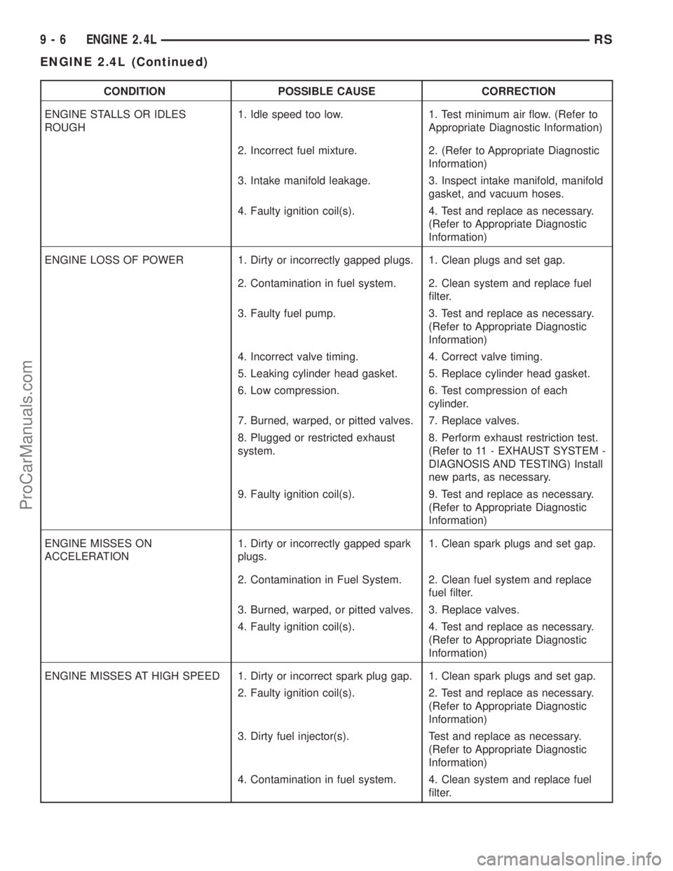
CONDITION POSSIBLE CAUSE CORRECTION
ENGINE STALLS OR IDLES
ROUGH1. Idle speed too low. 1. Test minimum air flow. (Refer to
Appropriate Diagnostic Information)
2. Incorrect fuel mixture. 2. (Refer to Appropriate Diagnostic
Information)
3. Intake manifold leakage. 3. Inspect intake manifold, manifold
gasket, and vacuum hoses.
4. Faulty ignition coil(s). 4. Test and replace as necessary.
(Refer to Appropriate Diagnostic
Information)
ENGINE LOSS OF POWER 1. Dirty or incorrectly gapped plugs. 1. Clean plugs and set gap.
2. Contamination in fuel system. 2. Clean system and replace fuel
filter.
3. Faulty fuel pump. 3. Test and replace as necessary.
(Refer to Appropriate Diagnostic
Information)
4. Incorrect valve timing. 4. Correct valve timing.
5. Leaking cylinder head gasket. 5. Replace cylinder head gasket.
6. Low compression. 6. Test compression of each
cylinder.
7. Burned, warped, or pitted valves. 7. Replace valves.
8. Plugged or restricted exhaust
system.8. Perform exhaust restriction test.
(Refer to 11 - EXHAUST SYSTEM -
DIAGNOSIS AND TESTING) Install
new parts, as necessary.
9. Faulty ignition coil(s). 9. Test and replace as necessary.
(Refer to Appropriate Diagnostic
Information)
ENGINE MISSES ON
ACCELERATION1. Dirty or incorrectly gapped spark
plugs.1. Clean spark plugs and set gap.
2. Contamination in Fuel System. 2. Clean fuel system and replace
fuel filter.
3. Burned, warped, or pitted valves. 3. Replace valves.
4. Faulty ignition coil(s). 4. Test and replace as necessary.
(Refer to Appropriate Diagnostic
Information)
ENGINE MISSES AT HIGH SPEED 1. Dirty or incorrect spark plug gap. 1. Clean spark plugs and set gap.
2. Faulty ignition coil(s). 2. Test and replace as necessary.
(Refer to Appropriate Diagnostic
Information)
3. Dirty fuel injector(s). Test and replace as necessary.
(Refer to Appropriate Diagnostic
Information)
4. Contamination in fuel system. 4. Clean system and replace fuel
filter.
9 - 6 ENGINE 2.4LRS
ENGINE 2.4L (Continued)
ProCarManuals.com
Page 1164 of 2321
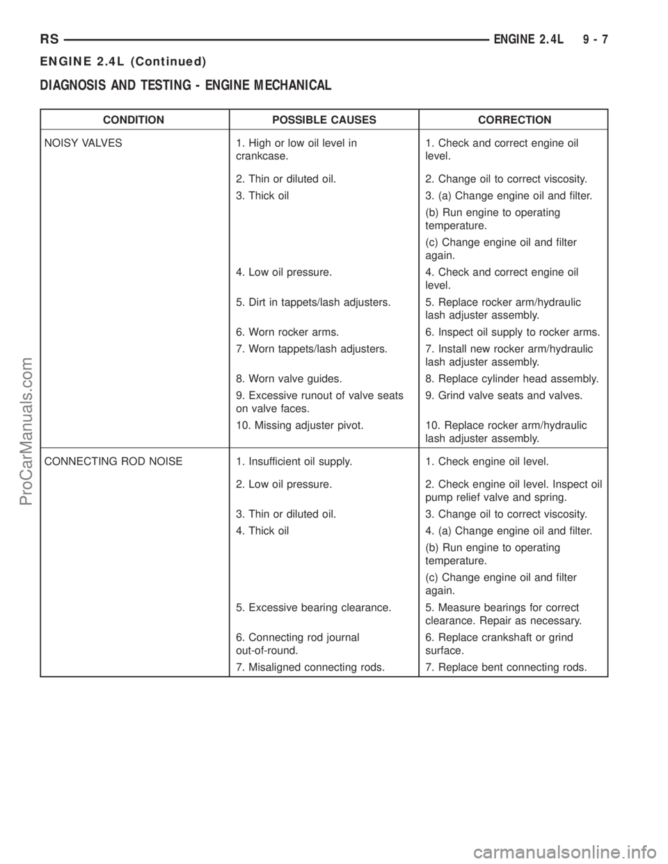
DIAGNOSIS AND TESTING - ENGINE MECHANICAL
CONDITION POSSIBLE CAUSES CORRECTION
NOISY VALVES 1. High or low oil level in
crankcase.1. Check and correct engine oil
level.
2. Thin or diluted oil. 2. Change oil to correct viscosity.
3. Thick oil 3. (a) Change engine oil and filter.
(b) Run engine to operating
temperature.
(c) Change engine oil and filter
again.
4. Low oil pressure. 4. Check and correct engine oil
level.
5. Dirt in tappets/lash adjusters. 5. Replace rocker arm/hydraulic
lash adjuster assembly.
6. Worn rocker arms. 6. Inspect oil supply to rocker arms.
7. Worn tappets/lash adjusters. 7. Install new rocker arm/hydraulic
lash adjuster assembly.
8. Worn valve guides. 8. Replace cylinder head assembly.
9. Excessive runout of valve seats
on valve faces.9. Grind valve seats and valves.
10. Missing adjuster pivot. 10. Replace rocker arm/hydraulic
lash adjuster assembly.
CONNECTING ROD NOISE 1. Insufficient oil supply. 1. Check engine oil level.
2. Low oil pressure. 2. Check engine oil level. Inspect oil
pump relief valve and spring.
3. Thin or diluted oil. 3. Change oil to correct viscosity.
4. Thick oil 4. (a) Change engine oil and filter.
(b) Run engine to operating
temperature.
(c) Change engine oil and filter
again.
5. Excessive bearing clearance. 5. Measure bearings for correct
clearance. Repair as necessary.
6. Connecting rod journal
out-of-round.6. Replace crankshaft or grind
surface.
7. Misaligned connecting rods. 7. Replace bent connecting rods.
RSENGINE 2.4L9-7
ENGINE 2.4L (Continued)
ProCarManuals.com