2001 DODGE TOWN AND COUNTRY brakes
[x] Cancel search: brakesPage 782 of 2321

8W-35 ANTILOCK BRAKES
Component Page
Body Control Module................ 8Wa-35-2
Brake Lamp Switch................. 8Wa-35-3
Controller Antilock Brake......... 8Wa-35-2, 3, 4
Diagnostic Junction Port.............. 8Wa-35-3
Engine Control Module............... 8Wa-35-3
Front Control Module................ 8Wa-35-3
Fuse 9 (IPM)....................... 8Wa-35-2
Fuse 21 (IPM)...................... 8Wa-35-2
Fuse 26 (IPM)...................... 8Wa-35-3
G100............................. 8Wa-35-2Component Page
G200............................. 8Wa-35-2
G300............................. 8Wa-35-3
Intelligent Power Module........... 8Wa-35-2, 3
Left Front Wheel Speed Sensor......... 8Wa-35-4
Left Rear Wheel Speed Sensor......... 8Wa-35-4
Powertrain Control Module............ 8Wa-35-3
Right Front Wheel Speed Sensor....... 8Wa-35-4
Right Rear Wheel Speed Sensor........ 8Wa-35-4
Traction Control Switch.............. 8Wa-35-2
RG8W-35 ANTILOCK BRAKES8Wa-35-1
ProCarManuals.com
Page 988 of 2321
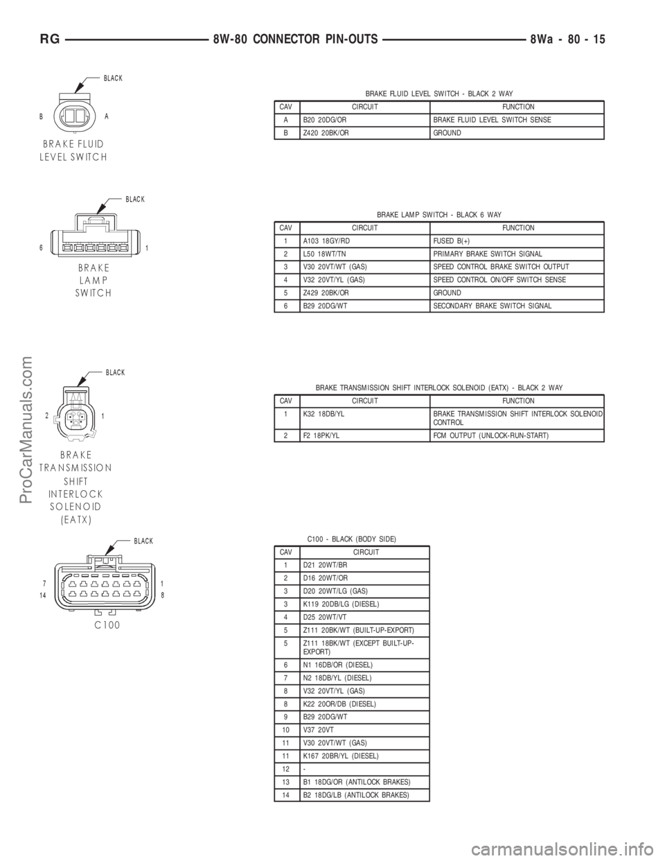
BRAKE FLUID LEVEL SWITCH - BLACK 2 WAY
CAV CIRCUIT FUNCTION
A B20 20DG/OR BRAKE FLUID LEVEL SWITCH SENSE
B Z420 20BK/OR GROUND
BRAKE LAMP SWITCH - BLACK 6 WAY
CAV CIRCUIT FUNCTION
1 A103 18GY/RD FUSED B(+)
2 L50 18WT/TN PRIMARY BRAKE SWITCH SIGNAL
3 V30 20VT/WT (GAS) SPEED CONTROL BRAKE SWITCH OUTPUT
4 V32 20VT/YL (GAS) SPEED CONTROL ON/OFF SWITCH SENSE
5 Z429 20BK/OR GROUND
6 B29 20DG/WT SECONDARY BRAKE SWITCH SIGNAL
BRAKE TRANSMISSION SHIFT INTERLOCK SOLENOID (EATX) - BLACK 2 WAY
CAV CIRCUIT FUNCTION
1 K32 18DB/YL BRAKE TRANSMISSION SHIFT INTERLOCK SOLENOID
CONTROL
2 F2 18PK/YL FCM OUTPUT (UNLOCK-RUN-START)
C100 - BLACK (BODY SIDE)
CAV CIRCUIT
1 D21 20WT/BR
2 D16 20WT/OR
3 D20 20WT/LG (GAS)
3 K119 20DB/LG (DIESEL)
4 D25 20WT/VT
5 Z111 20BK/WT (BUILT-UP-EXPORT)
5 Z111 18BK/WT (EXCEPT BUILT-UP-
EXPORT)
6 N1 16DB/OR (DIESEL)
7 N2 18DB/YL (DIESEL)
8 V32 20VT/YL (GAS)
8 K22 20OR/DB (DIESEL)
9 B29 20DG/WT
10 V37 20VT
11 V30 20VT/WT (GAS)
11 K167 20BR/YL (DIESEL)
12 -
13 B1 18DG/OR (ANTILOCK BRAKES)
14 B2 18DG/LB (ANTILOCK BRAKES)
RG8W-80 CONNECTOR PIN-OUTS8Wa-80-15
ProCarManuals.com
Page 989 of 2321
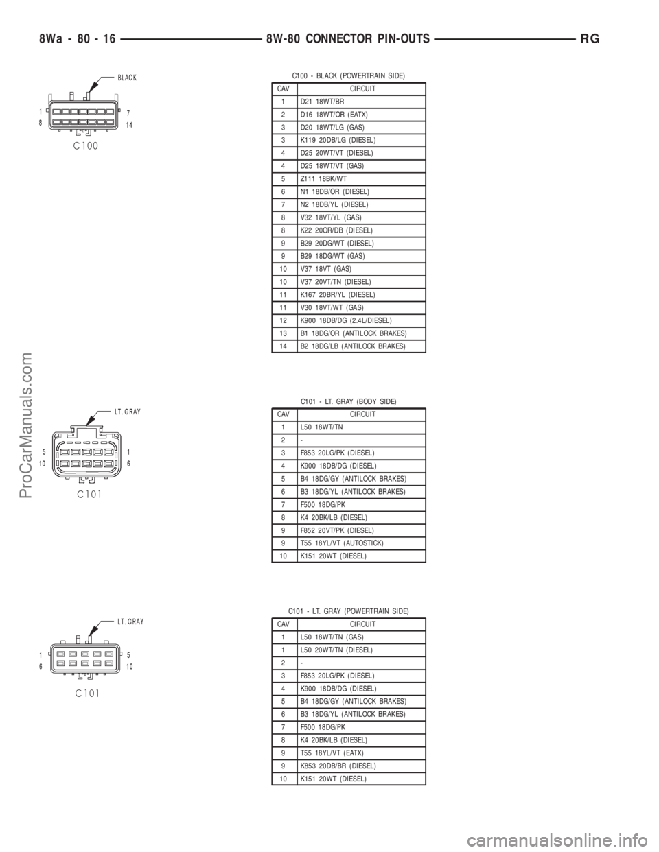
C100 - BLACK (POWERTRAIN SIDE)
CAV CIRCUIT
1 D21 18WT/BR
2 D16 18WT/OR (EATX)
3 D20 18WT/LG (GAS)
3 K119 20DB/LG (DIESEL)
4 D25 20WT/VT (DIESEL)
4 D25 18WT/VT (GAS)
5 Z111 18BK/WT
6 N1 18DB/OR (DIESEL)
7 N2 18DB/YL (DIESEL)
8 V32 18VT/YL (GAS)
8 K22 20OR/DB (DIESEL)
9 B29 20DG/WT (DIESEL)
9 B29 18DG/WT (GAS)
10 V37 18VT (GAS)
10 V37 20VT/TN (DIESEL)
11 K167 20BR/YL (DIESEL)
11 V30 18VT/WT (GAS)
12 K900 18DB/DG (2.4L/DIESEL)
13 B1 18DG/OR (ANTILOCK BRAKES)
14 B2 18DG/LB (ANTILOCK BRAKES)
C101 - LT. GRAY (BODY SIDE)
CAV CIRCUIT
1 L50 18WT/TN
2-
3 F853 20LG/PK (DIESEL)
4 K900 18DB/DG (DIESEL)
5 B4 18DG/GY (ANTILOCK BRAKES)
6 B3 18DG/YL (ANTILOCK BRAKES)
7 F500 18DG/PK
8 K4 20BK/LB (DIESEL)
9 F852 20VT/PK (DIESEL)
9 T55 18YL/VT (AUTOSTICK)
10 K151 20WT (DIESEL)
C101 - LT. GRAY (POWERTRAIN SIDE)
CAV CIRCUIT
1 L50 18WT/TN (GAS)
1 L50 20WT/TN (DIESEL)
2-
3 F853 20LG/PK (DIESEL)
4 K900 18DB/DG (DIESEL)
5 B4 18DG/GY (ANTILOCK BRAKES)
6 B3 18DG/YL (ANTILOCK BRAKES)
7 F500 18DG/PK
8 K4 20BK/LB (DIESEL)
9 T55 18YL/VT (EATX)
9 K853 20DB/BR (DIESEL)
10 K151 20WT (DIESEL)
8Wa - 80 - 16 8W-80 CONNECTOR PIN-OUTSRG
ProCarManuals.com
Page 1042 of 2321
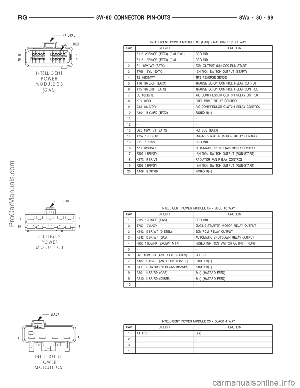
INTELLIGENT POWER MODULE C3 (GAS) - NATURAL/RED 20 WAY
CAV CIRCUIT FUNCTION
1 Z115 20BK/OR (EATX) (3.3L/3.8L) GROUND
1 Z115 18BK/OR (EATX) (2.4L) GROUND
2 F1 18PK/WT (EATX) FCM OUTPUT (UNLOCK-RUN-START)
3 T751 18YL (EATX) IGNITION SWITCH OUTPUT (START)
4 T2 18DG/WT TRS REVERSE SENSE
5 T16 18YL/OR (EATX) TRANSMISSION CONTROL RELAY OUTPUT
6 T15 18YL/BR (EATX) TRANSMISSION CONTROL RELAY CONTROL
7 C3 18DB/YL A/C COMPRESSOR CLUTCH RELAY OUTPUT
8 K31 18BR FUEL PUMP RELAY CONTROL
9 C13 18LB/OR A/C COMPRESSOR CLUTCH RELAY CONTROL
10 A104 18YL/RD (EATX) FUSED B(+)
11 - -
12 - -
13 D25 18WT/VT (EATX) PCI BUS (EATX)
14 T752 18DG/OR ENGINE STARTER MOTOR RELAY CONTROL
15 Z116 18BK/VT GROUND
16 K51 18BR/WT AUTOMATIC SHUTDOWN RELAY CONTROL
17 F202 18PK/GY IGNITION SWITCH OUTPUT (RUN-START)
18 K173 18BR/VT RADIATOR FAN RELAY CONTROL
19 F202 18PK/GY IGNITION SWITCH OUTPUT (RUN-START)
20 A109 18OR/RD FUSED B(+)
INTELLIGENT POWER MODULE C4 - BLUE 10 WAY
CAV CIRCUIT FUNCTION
1 Z127 12BK/DG (GAS) GROUND
2 T750 12YL/GY ENGINE STARTER MOTOR RELAY OUTPUT
3 K342 16BR/WT (DIESEL) ECM/PCM RELAY OUTPUT
3 K342 16BR/WT (GAS) AUTOMATIC SHUTDOWN RELAY OUTPUT
4 F500 16DG/PK (EXCEPT MTX)) FUSED IGNITION SWITCH OUTPUT (RUN)
5- -
6 D25 16WT/VT (ANTILOCK BRAKES) PCI BUS
7 A107 12TN/RD (ANTILOCK BRAKES) FUSED B(+)
8 A111 12DG/RD (ANTILOCK BRAKES) FUSED B(+)
9 A701 14BR/RD (GAS) B(+) (HAZARD FEED)
9 A710 14BR/RD (DIESEL) B(+) (HAZARD FEED)
10 - -
INTELLIGENT POWER MODULE C5 - BLACK 4 WAY
CAV CIRCUIT FUNCTION
1 A1 4RD B(+)
2- -
3- -
4- -
RG8W-80 CONNECTOR PIN-OUTS8Wa-80-69
ProCarManuals.com
Page 1596 of 2321
(2) Loosen pan bolts and tap the pan at one corner
to break it loose allowing fluid to drain, then remove
the oil pan.
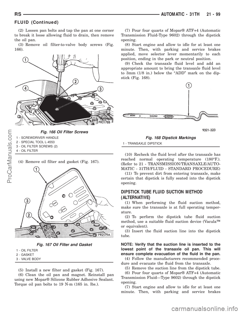
(3) Remove oil filter-to-valve body screws (Fig.
166).
(4) Remove oil filter and gasket (Fig. 167).
(5) Install a new filter and gasket (Fig. 167).
(6) Clean the oil pan and magnet. Reinstall pan
using new Moparž Silicone Rubber Adhesive Sealant.
Torque oil pan bolts to 19 N´m (165 in. lbs.).(7) Pour four quarts of Moparž ATF+4 (Automatic
Transmission Fluid-Type 9602) through the dipstick
opening.
(8) Start engine and allow to idle for at least one
minute. Then, with parking and service brakes
applied, move selector lever momentarily to each
position, ending in the park or neutral position.
(9) Check the transaxle fluid level and add an
appropriate amount to bring the transaxle fluid level
to 3mm (1/8 in.) below the ªADDº mark on the dip-
stick (Fig. 168).
(10) Recheck the fluid level after the transaxle has
reached normal operating temperature (180ÉF.).
(Refer to 21 - TRANSMISSION/TRANSAXLE/AUTO-
MATIC - 31TH/FLUID - STANDARD PROCEDURE)
(11) To prevent dirt from entering transaxle, make
certain that dipstick is fully seated into the dipstick
opening.
DIPSTICK TUBE FLUID SUCTION METHOD
(ALTERNATIVE)
(1) When performing the fluid suction method,
make sure the transaxle is at full operating temper-
ature.
(2) To perform the dipstick tube fluid suction
method, use a suitable fluid suction device (VaculaŸ
or equivalent).
(3) Insert the fluid suction line into the dipstick
tube.
NOTE: Verify that the suction line is inserted to the
lowest point of the transaxle oil pan. This will
ensure complete evacuation of the fluid in the pan.
(4) Follow the manufacturers recommended proce-
dure and evacuate the fluid from the transaxle.
(5) Remove the suction line from the dipstick tube.
(6) Pour four quarts of Moparž ATF+4 (Automatic
Transmission FluidÐType 9602) through the dipstick
opening.
(7) Start engine and allow to idle for at least one
minute. Then, with parking and service brakes
Fig. 166 Oil Filter Screws
1 - SCREWDRIVER HANDLE
2 - SPECIAL TOOL L-4553
3 - OIL FILTER SCREWS (2)
4 - OIL FILTER
Fig. 167 Oil Filter and Gasket
1 - OIL FILTER
2 - GASKET
3 - VALVE BODY
Fig. 168 Dipstick Markings
1 - TRANSAXLE DIPSTICK
RSAUTOMATIC - 31TH21-99
FLUID (Continued)
ProCarManuals.com
Page 1745 of 2321
(5) Pour four quarts of Moparž ATF+4 (Automatic
Transmission Fluid) Type 9602 through the dipstick
opening.
(6) Start engine and allow to idle for at least one
minute. Then, with parking and service brakes
applied, move selector lever momentarily to each
position, ending in the park or neutral position.
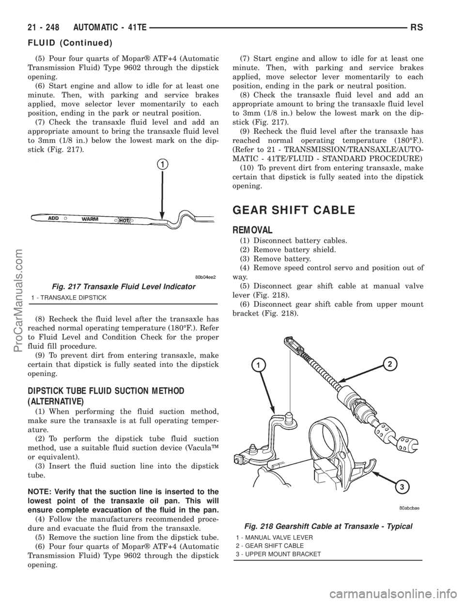
(7) Check the transaxle fluid level and add an
appropriate amount to bring the transaxle fluid level
to 3mm (1/8 in.) below the lowest mark on the dip-
stick (Fig. 217).
(8) Recheck the fluid level after the transaxle has
reached normal operating temperature (180ÉF.). Refer
to Fluid Level and Condition Check for the proper
fluid fill procedure.
(9) To prevent dirt from entering transaxle, make
certain that dipstick is fully seated into the dipstick
opening.
DIPSTICK TUBE FLUID SUCTION METHOD
(ALTERNATIVE)
(1) When performing the fluid suction method,
make sure the transaxle is at full operating temper-
ature.
(2) To perform the dipstick tube fluid suction
method, use a suitable fluid suction device (VaculaŸ
or equivalent).
(3) Insert the fluid suction line into the dipstick
tube.
NOTE: Verify that the suction line is inserted to the
lowest point of the transaxle oil pan. This will
ensure complete evacuation of the fluid in the pan.
(4) Follow the manufacturers recommended proce-
dure and evacuate the fluid from the transaxle.
(5) Remove the suction line from the dipstick tube.
(6) Pour four quarts of Moparž ATF+4 (Automatic
Transmission Fluid) Type 9602 through the dipstick
opening.(7) Start engine and allow to idle for at least one
minute. Then, with parking and service brakes
applied, move selector lever momentarily to each
position, ending in the park or neutral position.
(8) Check the transaxle fluid level and add an
appropriate amount to bring the transaxle fluid level
to 3mm (1/8 in.) below the lowest mark on the dip-
stick (Fig. 217).
(9) Recheck the fluid level after the transaxle has
reached normal operating temperature (180ÉF.).
(Refer to 21 - TRANSMISSION/TRANSAXLE/AUTO-
MATIC - 41TE/FLUID - STANDARD PROCEDURE)
(10) To prevent dirt from entering transaxle, make
certain that dipstick is fully seated into the dipstick
opening.
GEAR SHIFT CABLE
REMOVAL
(1) Disconnect battery cables.
(2) Remove battery shield.
(3) Remove battery.
(4) Remove speed control servo and position out of
way.
(5) Disconnect gear shift cable at manual valve
lever (Fig. 218).
(6) Disconnect gear shift cable from upper mount
bracket (Fig. 218).
Fig. 217 Transaxle Fluid Level Indicator
1 - TRANSAXLE DIPSTICK
Fig. 218 Gearshift Cable at Transaxle - Typical
1 - MANUAL VALVE LEVER
2 - GEAR SHIFT CABLE
3 - UPPER MOUNT BRACKET
21 - 248 AUTOMATIC - 41TERS
FLUID (Continued)
ProCarManuals.com
Page 1897 of 2321
²Visual Buzziness (high frequency, rapid vibra-
tion up and down)
To rule out vibrations due to brakes or powertrain:
²Lightly apply brakes at speed; if vibration occurs
or is enhanced, vibration is likely due to causes other
than tire and wheel assemblies.
²Shift transmission into neutral while vibration
is occurring; if vibration is eliminated, vibration is
likely due to causes other than tire and wheel assem-
blies.
For brake vibrations, (Refer to 5 - BRAKES -
BASE/HYDRAULIC/MECHANICAL/ROTORS -
DIAGNOSIS AND TESTING).
For powertrain vibrations, (Refer to 3 - DIFFER-
ENTIAL & DRIVELINE - DIAGNOSIS AND TEST-
ING).
For tire and wheel assembly vibrations, continue
with this diagnosis an testing procedure.
TIRE AND WHEEL BALANCE
(1) Balance the tire and wheel assemblies as nec-
essary following the wheel balancer manufacturer's
instructions and using the information listed in Stan-
dard Procedure - Tire And Wheel Balance. (Refer to
22 - TIRES/WHEELS - STANDARD PROCEDURE)
(2) Road test the vehicle for at least 5 miles, fol-
lowing the format described in Road Test.
(3) If the vibration persists, continue with this
diagnosis an testing procedure.
TIRE AND WHEEL RUNOUT/MATCH MOUNTING
(1)System Radial Runout.This on-the-vehicle
system check will measure the radial runout includ-
ing the hub, wheel and tire.
(a) Raise vehicle so tires clear floor. Refer to
Hoisting in Lubrication and Maintenance.
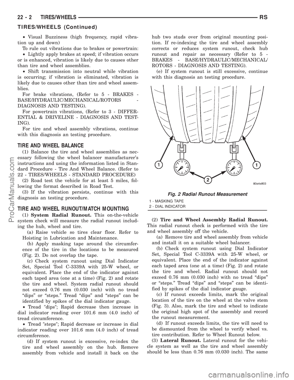
(b) Apply masking tape around the circumfer-
ence of the tire in the locations to be measured
(Fig. 2). Do not overlap the tape.
(c) Check system runout using Dial Indicator
Set, Special Tool C-3339A with 25-W wheel, or
equivalent. Place the end of the indicator against
each taped area (one at a time) (Fig. 2) and rotate
the tire and wheel. System radial runout should
not exceed 0.76 mm (0.030 inch) with no tread
ªdipsº or ªsteps.º Tread ªdipsº and ªstepsº can be
identified by spikes of the dial indicator gauge.
²Tread9dips9; Rapid decrease then increase in
dial indicator reading over 101.6 mm (4.0 inch) of
tread circumference.
²Tread9steps9; Rapid decrease or increase in dial
indicator reading over 101.6 mm (4.0 inch) of tread
circumference.
(d) If system runout is excessive, re-index the
tire and wheel assembly on the hub. Remove
assembly from vehicle and install it back on thehub two studs over from original mounting posi-
tion. If re-indexing the tire and wheel assembly
corrects or reduces system runout, check hub
runout and repair as necessary (Refer to 5 -
BRAKES - BASE/HYDRAULIC/MECHANICAL/
ROTORS - DIAGNOSIS AND TESTING).
(e) If system runout is still excessive, continue
with this diagnosis an testing procedure.
(2)Tire and Wheel Assembly Radial Runout.
This radial runout check is performed with the tire
and wheel assembly off the vehicle.
(a) Remove tire and wheel assembly from vehicle
and install it on a suitable wheel balancer.
(b) Check system runout using Dial Indicator
Set, Special Tool C-3339A with 25-W wheel, or
equivalent. Place the end of the indicator against
each taped area (one at a time) (Fig. 2) and rotate
the tire and wheel. Radial runout should not
exceed 0.76 mm (0.030 inch) with no tread ªdipsº
or ªsteps.º Tread ªdipsº and ªstepsº can be identi-
fied by spikes of the dial indicator gauge.
(c) If runout exceeds limits, mark the original
location of the tire on the wheel at the valve stem
(Fig. 3). Also, mark the tire and wheel to indicate
the original high spot of the assembly and record
the runout measurement.
(d) If runout exceeds limits, the tire will need to
be dismounted from the wheel to verify wheel vs.
tire contribution. Refer to Wheel Runout below.
(3)Lateral Runout.Lateral runout for the vehi-
cle system as well as the tire and wheel assembly
should be less than 0.76 mm (0.030 inch). The same
Fig. 2 Radial Runout Measurement
1 - MASKING TAPE
2 - DIAL INDICATOR
22 - 2 TIRES/WHEELSRS
TIRES/WHEELS (Continued)
ProCarManuals.com
Page 1903 of 2321
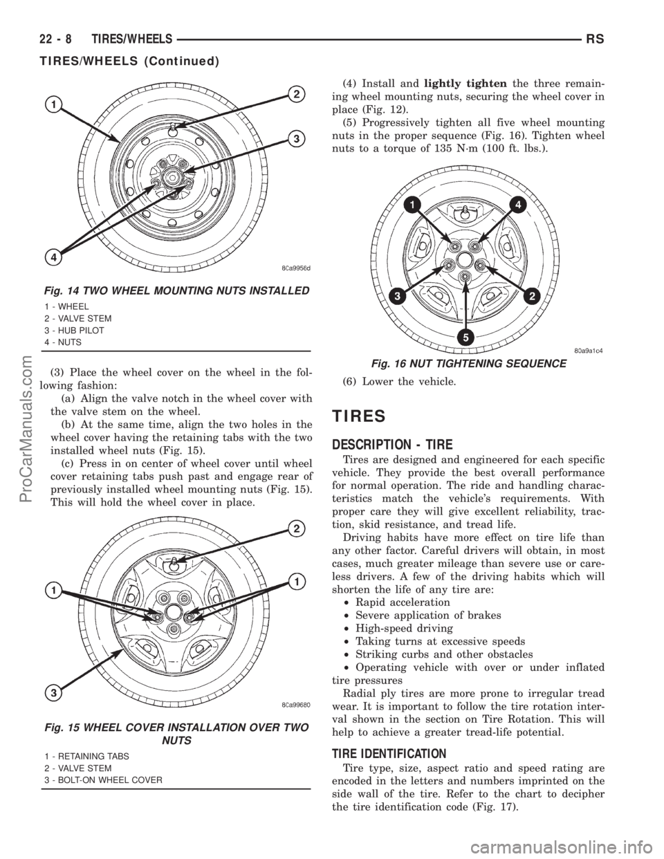
(3) Place the wheel cover on the wheel in the fol-
lowing fashion:
(a) Align the valve notch in the wheel cover with
the valve stem on the wheel.
(b) At the same time, align the two holes in the
wheel cover having the retaining tabs with the two
installed wheel nuts (Fig. 15).
(c) Press in on center of wheel cover until wheel
cover retaining tabs push past and engage rear of
previously installed wheel mounting nuts (Fig. 15).
This will hold the wheel cover in place.(4) Install andlightly tightenthe three remain-
ing wheel mounting nuts, securing the wheel cover in
place (Fig. 12).
(5) Progressively tighten all five wheel mounting
nuts in the proper sequence (Fig. 16). Tighten wheel
nuts to a torque of 135 N´m (100 ft. lbs.).
(6) Lower the vehicle.
TIRES
DESCRIPTION - TIRE
Tires are designed and engineered for each specific
vehicle. They provide the best overall performance
for normal operation. The ride and handling charac-
teristics match the vehicle's requirements. With
proper care they will give excellent reliability, trac-
tion, skid resistance, and tread life.
Driving habits have more effect on tire life than
any other factor. Careful drivers will obtain, in most
cases, much greater mileage than severe use or care-
less drivers. A few of the driving habits which will
shorten the life of any tire are:
²Rapid acceleration
²Severe application of brakes
²High-speed driving
²Taking turns at excessive speeds
²Striking curbs and other obstacles
²Operating vehicle with over or under inflated
tire pressures
Radial ply tires are more prone to irregular tread
wear. It is important to follow the tire rotation inter-
val shown in the section on Tire Rotation. This will
help to achieve a greater tread-life potential.
TIRE IDENTIFICATION
Tire type, size, aspect ratio and speed rating are
encoded in the letters and numbers imprinted on the
side wall of the tire. Refer to the chart to decipher
the tire identification code (Fig. 17).
Fig. 14 TWO WHEEL MOUNTING NUTS INSTALLED
1 - WHEEL
2 - VALVE STEM
3 - HUB PILOT
4 - NUTS
Fig. 15 WHEEL COVER INSTALLATION OVER TWO
NUTS
1 - RETAINING TABS
2 - VALVE STEM
3 - BOLT-ON WHEEL COVER
Fig. 16 NUT TIGHTENING SEQUENCE
22 - 8 TIRES/WHEELSRS
TIRES/WHEELS (Continued)
ProCarManuals.com