2001 DODGE TOWN AND COUNTRY brakes
[x] Cancel search: brakesPage 308 of 2321
COOLING 2.5L TURBO DIESEL
TABLE OF CONTENTS
page page
COOLING 2.5L TURBO DIESEL
DESCRIPTION............................1
DIAGNOSIS AND TESTING..................1
COOLING SYSTEM......................1
COOLING SYSTEM LEAK TEST.............6
COOLING SYSTEM FLOW CHECK..........7COOLING SYSTEM AERATION.............7
CLEANING...............................7
INSPECTION.............................7
SPECIFICATIONS.........................8
ACCESSORY DRIVE.......................9
ENGINE................................14
COOLING 2.5L TURBO DIESEL
DESCRIPTION - COOLING SYSTEM
The cooling system regulates engine operating tem-
perature. It allows the engine to reach normal oper-
ating temperature as quickly as possible, maintains
normal operating temperature and prevents over-
heating.
The cooling system also provides a means of heat-
ing the passenger compartment. The cooling system
is pressurized and uses a centrifugal water pump to
circulate coolant throughout the system. A separate
and remotely mounted, pressurized coolant tank
using a pressure/vent cap is used.
COOLING SYSTEM COMPONENTS
The cooling system consists of:
²Charge Air Cooler
²Electric Cooling Fans
²A aluminum-core radiator with plastic side
tanks
²A separate pressurized coolant tank
²A pressure/vent cap on the coolant tank
²Fan shroud
²Thermostat
²Coolant
²Low coolant warning lamp
²Coolant temperature gauge
²Water pump
²Hoses and hose clamps
DIAGNOSIS AND TESTING - COOLING SYSTEM
Establish what driving conditions caused the com-
plaint. Abnormal loads on the cooling system such as
the following may be the cause:
(1) PROLONGED IDLE, VERY HIGH AMBIENT
TEMPERATURE, SLIGHT TAIL WIND AT IDLE,
SLOW TRAFFIC, TRAFFIC JAMS, HIGH SPEED
OR STEEP GRADES.
Driving techniques that avoid overheating are:
²Idle with A/C off when temperature gauge is at
end of normal range.
²Increasing engine speed for more air flow is rec-
ommended.
(2) TRAILER TOWING:
Consult Trailer Towing section of owners manual.
Do not exceed limits.
(3) RECENT SERVICE OR ACCIDENT REPAIR:
Determine if any recent service has been per-
formed on vehicle that may effect cooling system.
This may be:
²Engine adjustments (incorrect timing)
²Slipping engine accessory drive belt
²Brakes (possibly dragging)
²Changed parts (incorrect water pump)
²Reconditioned radiator or cooling system refill-
ing (possibly under filled or air trapped in system).
NOTE: If investigation reveals none of the previous
items as a cause for an engine overheating com-
plaint, refer to following Cooling System Diagnosis
charts.
These charts are to be used as a quick-reference
only.
RGCOOLING 2.5L TURBO DIESEL7a-1
ProCarManuals.com
Page 310 of 2321
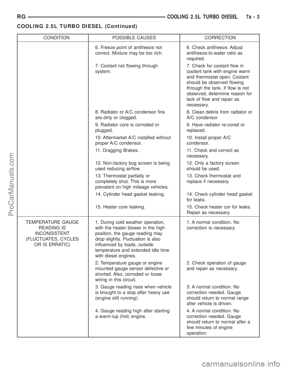
CONDITION POSSIBLE CAUSES CORRECTION
6. Freeze point of antifreeze not
correct. Mixture may be too rich.6. Check antifreeze. Adjust
antifreeze-to-water ratio as
required.
7. Coolant not flowing through
system.7. Check for coolant flow in
coolant tank with engine warm
and thermostat open. Coolant
should be observed flowing
through the tank. If flow is not
observed, determine reason for
lack of flow and repair as
necessary.
8. Radiator or A/C condensor fins
are dirty or clogged.8. Clean debris from radiator or
A/C condensor
9. Radiator core is corroded or
plugged.9. Have radiator re-cored or
replaced.
10. Aftermarket A/C installed without
proper A/C condensor.10. Install proper A/C
condensor.
11. Dragging Brakes. 11. Check and correct as
necessary.
12. Non-factory bug screen is being
used reducing airflow.12. Only a factory screen
should be used.
13. Thermostat partially or
completely shut. This is more
prevalent on high mileage vehicles.13. Check thermostat and
replace if necessary.
14. Cylinder head gasket leaking. 14. Check cylinder head gasket
for leaks.
15. Heater core leaking. 15. Check heater cor for leaks.
Repair as necessary.
TEMPERATURE GAUGE
READING IS
INCONSISTENT
(FLUCTUATES, CYCLES
OR IS ERRATIC)1. During cold weather operation,
with the heater blower in the high
position, the gauge reading may
drop slightly. Fluctuation is also
influenced by loads, outside
temperature and extended idle time
with diesel engines.1. A normal condition. No
correction is necessary.
2. Temperature gauge or engine
mounted gauge sensor defective or
shorted. Also, corroded or loose
wiring in this circuit.2. Check operation of gauge
and repair as necessary.
3. Gauge reading rises when vehicle
is brought to a stop after heavy use
(engine still running).3. A normal condition. No
correction needed. Gauge
should return to normal range
after vehicle is driven.
4. Gauge reading high after starting
a warm-iup (hot) engine.4. A normal condition. No
correction needed. Gauge
should return to normal after a
few minutes of engine
operation.
RGCOOLING 2.5L TURBO DIESEL7a-3
COOLING 2.5L TURBO DIESEL (Continued)
ProCarManuals.com
Page 360 of 2321

OPERATION
The Body Control Module (BCM) is designed to
control and integrate many of the electronic features
and functions of the vehicle. The microprocessor-
based BCM hardware and software monitors many
hard wired switch and sensor inputs as well as those
resources it shares with other electronic modules in
the vehicle through its communication over the PCI
data bus network. The internal programming and all
of these inputs allow the BCM microprocessor to
determine the tasks it needs to perform and their
priorities, as well as both the standard and optional
features that it should provide. The BCM program-
ming then performs those tasks and provides those
features through both PCI data bus communication
with other electronic modules and through hard
wired low current outputs to a number of relays.
These relays provide the BCM with the ability to
control numerous high current accessory systems in
the vehicle.
The BCM monitors its own internal circuitry as
well as many of its input and output circuits, and
will store a Diagnostic Trouble Code (DTC) in elec-
tronic memory for any failure it detects. These DTCs
can be retrieved and diagnosed using a DRBIIItscan
tool. Refer to the appropriate diagnostic information.
REMOVAL
(1) Disconnect and isolate the battery negative
cable.
(2) Remove lower steering column cover and knee
blocker reinforcement.
(3) Disconnect two wire connectors from bottom of
Body Control Module (BCM)
(4) Remove bolts holding the BCM to the dash
panel mounting bracket.
(5) Remove the BCM from the mounting bracket.
INSTALLATION
(1) Install the BCM onto the mounting bracket.
(2) Install the bolts holding the BCM to dash
panel mounting bracket.
(3) Connect two wire connectors to the bottom of
the BCM.
(4) Install the lower steering column cover and
knee blocker reinforcement.
(5) Connect the battery negative cable.
CONTROLLER ANTILOCK
BRAKE
DESCRIPTION
The controller antilock brake (CAB) is a micropro-
cessor-based device which monitors the antilock
brake system (ABS) during normal braking and con-trols it when the vehicle is in an ABS stop. The CAB
is mounted to the HCU as part of the integrated con-
trol unit (ICU) (Fig. 1). The CAB uses a 24-way elec-
trical connector on the vehicle wiring harness. The
power source for the CAB is through the ignition
switch in the RUN or ON position. The CAB is on
the PCI bus.
OPERATION
The primary functions of the controller antilock
brake (CAB) are to:
²Monitor the antilock brake system for proper
operation.
²Detect wheel locking or wheel slipping tenden-
cies by monitoring the speed of all four wheels of the
vehicle.
²Control fluid modulation to the wheel brakes
while the system is in an ABS mode.
²Store diagnostic information.
²Provide communication to the DRBIIItscan tool
while in diagnostic mode.
²Illuminate the amber ABS warning indicator
lamp.
²(With traction control only) Illuminate the TRAC
ON lamp in the message center on the instrument
panel when a traction control event occurs.
²(with traction control only) Illuminate the TRAC
OFF lamp when the amber ABS warning indicator
lamp illuminates.
The CAB constantly monitors the antilock brake
system for proper operation. If the CAB detects a
fault, it will turn on the amber ABS warning indica-
tor lamp and disable the antilock braking system.
Fig. 1 INTEGRATED CONTROL UNIT (ICU)
1 - PUMP/MOTOR
2 - HCU
3 - PUMP/MOTOR CONNECTOR
4 - CAB
RSELECTRONIC CONTROL MODULES8E-3
BODY CONTROL MODULE (Continued)
ProCarManuals.com
Page 384 of 2321

Schedule Condition Expected Operation
HotOil temperature at start-up above
80É F± Normal operation (upshift,
kickdowns, and coastdowns)
± Full EMCC, no PEMCC except to
engage FEMCC (except at closed
throttle at speeds above 70-83 mph)
OverheatOil temperature above 240É F or
engine coolant temperature above
244É F± Delayed 2-3 upshift (25-32 mph)
± Delayed 3-4 upshift (41-48 mph)
± 3rd gear FEMCC from 30-48 mph
± 3rd gear PEMCC from 27-31 mph
Super OverheatOil temperature above 260É F ± All9Overheat9shift schedule
features apply
± 2nd gear PEMCC above 22 mph
± Above 22 mph the torque
converter will not unlock unless the
throttle is closed or if a wide open
throttle 2nd PEMCC to 1 kickdown
is made
STANDARD PROCEDURE - PINION FACTOR
SETTING
NOTE: This procedure must be performed if the
Transmission Control Module (TCM) has been
replaced with a NEW or replacement unit. Failure to
perform this procedure will result in an inoperative
or improperly calibrated speedometer.
The vehicle speed readings for the speedometer are
taken from the output speed sensor. The TCM must
be calibrated to the different combinations of equip-
ment (final drive and tires) available. Pinion Factor
allows the technician to set the Transmission Control
Module initial setting so that the speedometer read-
ings will be correct. To properly read and/or reset the
Pinion Factor, it is necessary to use a DRB scan tool.
(1) Plug the DRB scan tool into the diagnostic con-
nector located under the instrument panel.
(2) Select the Transmission menu.
(3) Select the Miscellaneous menu.
(4) Select Pinion Factor. Then follow the instruc-
tions on the DRB scan tool screen.
STANDARD PROCEDURE - QUICK LEARN
PROCEDURE
The quick learn procedure requires the use of the
DRB scan tool. This program allows the electronic
transaxle system to recalibrate itself. This will pro-
vide the best possible transaxle operation.NOTE: The quick learn procedure should be per-
formed if any of the following procedures are per-
formed:
²Transaxle Assembly Replacement
²Transmission Control Module Replacement
²Solenoid/Pressure Switch Assembly Replacement
²Clutch Plate and/or Seal Replacement
²Valve Body Replacement or Recondition
To perform the Quick Learn Procedure, the follow-
ing conditions must be met:
²The brakes must be applied
²The engine speed must be above 500 rpm
²The throttle angle (TPS) must be less than 3
degrees
²The shift lever position must stay until
prompted to shift to overdrive
²The shift lever position must stay in overdrive
after the Shift to Overdrive prompt until the DRB
indicates the procedure is complete
²The calculated oil temperature must be above
60É and below 200É
(1) Plug the DRB scan tool into the diagnostic con-
nector. The connector is located under the instrument
panel.
(2) Go to the Transmission screen.
(3) Go to the Miscellaneous screen.
(4) Select Quick Learn Procedure. Follow the
instructions of the DRB to perform the Quick Learn
Procedure.
RSELECTRONIC CONTROL MODULES8E-27
TRANSMISSION CONTROL MODULE (Continued)
ProCarManuals.com
Page 481 of 2321
CAUTION: The switch can only be adjusted once.
That is during initial installation of the switch. If the
switch is not adjusted properly or has been
removed for some service, a new switch must be
installed and adjusted.
REMOVAL - BRAKE LAMP SWITCH
(1) Disconnect and isolate the battery negative
cable from its post on the battery.
(2) Remove silencer panel below steering column
and knee blocker.
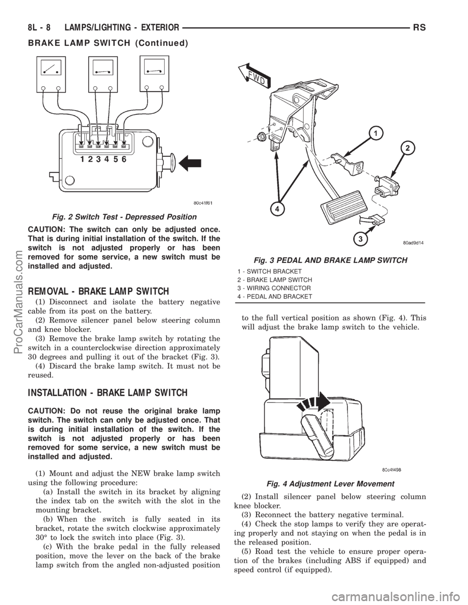
(3) Remove the brake lamp switch by rotating the
switch in a counterclockwise direction approximately
30 degrees and pulling it out of the bracket (Fig. 3).
(4) Discard the brake lamp switch. It must not be
reused.
INSTALLATION - BRAKE LAMP SWITCH
CAUTION: Do not reuse the original brake lamp
switch. The switch can only be adjusted once. That
is during initial installation of the switch. If the
switch is not adjusted properly or has been
removed for some service, a new switch must be
installed and adjusted.
(1) Mount and adjust the NEW brake lamp switch
using the following procedure:
(a) Install the switch in its bracket by aligning
the index tab on the switch with the slot in the
mounting bracket.
(b) When the switch is fully seated in its
bracket, rotate the switch clockwise approximately
30É to lock the switch into place (Fig. 3).
(c) With the brake pedal in the fully released
position, move the lever on the back of the brake
lamp switch from the angled non-adjusted positionto the full vertical position as shown (Fig. 4). This
will adjust the brake lamp switch to the vehicle.
(2) Install silencer panel below steering column
knee blocker.
(3) Reconnect the battery negative terminal.
(4) Check the stop lamps to verify they are operat-
ing properly and not staying on when the pedal is in
the released position.
(5) Road test the vehicle to ensure proper opera-
tion of the brakes (including ABS if equipped) and
speed control (if equipped).
Fig. 2 Switch Test - Depressed Position
Fig. 3 PEDAL AND BRAKE LAMP SWITCH
1 - SWITCH BRACKET
2 - BRAKE LAMP SWITCH
3 - WIRING CONNECTOR
4 - PEDAL AND BRACKET
Fig. 4 Adjustment Lever Movement
8L - 8 LAMPS/LIGHTING - EXTERIORRS
BRAKE LAMP SWITCH (Continued)
ProCarManuals.com
Page 596 of 2321
SPEED CONTROL
TABLE OF CONTENTS
page page
SPEED CONTROL
DESCRIPTION............................1
OPERATION.............................1
DIAGNOSIS AND TESTING..................3
ROAD TEST............................3
SPECIFICATIONS.........................3
CABLE
DESCRIPTION............................3
OPERATION.............................3
REMOVAL...............................3
INSTALLATION............................4
SERVO
DESCRIPTION............................4OPERATION.............................4
REMOVAL...............................4
INSTALLATION............................4
SWITCH
DESCRIPTION............................5
OPERATION.............................5
REMOVAL...............................5
INSTALLATION............................5
VACUUM RESERVOIR
DESCRIPTION............................6
OPERATION.............................6
REMOVAL...............................6
INSTALLATION............................6
SPEED CONTROL
DESCRIPTION
The speed control system is electronically con-
trolled and vacuum operated. The electronic control
is integrated into the powertrain control module,
located on the driver's side under the speed control
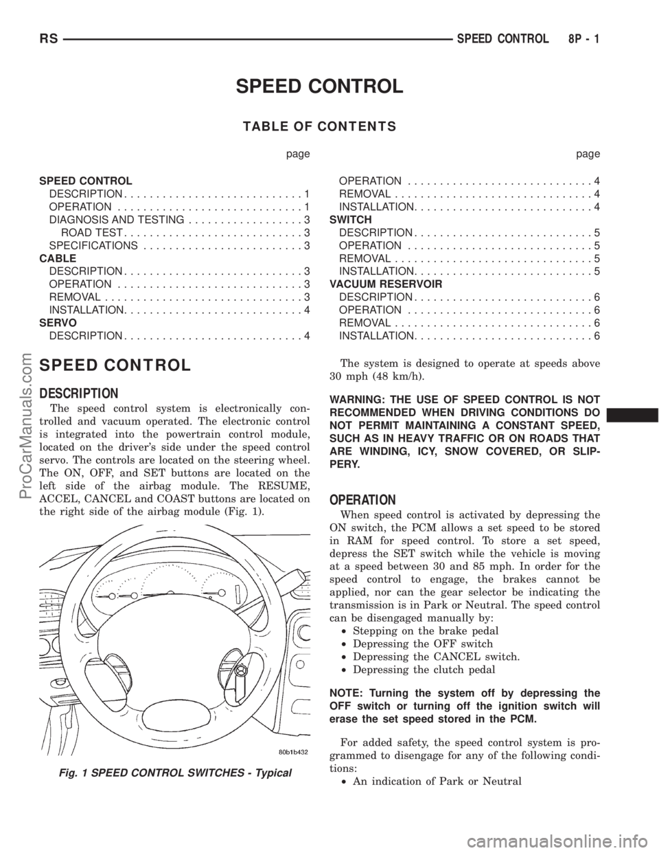
servo. The controls are located on the steering wheel.
The ON, OFF, and SET buttons are located on the
left side of the airbag module. The RESUME,
ACCEL, CANCEL and COAST buttons are located on
the right side of the airbag module (Fig. 1).The system is designed to operate at speeds above
30 mph (48 km/h).
WARNING: THE USE OF SPEED CONTROL IS NOT
RECOMMENDED WHEN DRIVING CONDITIONS DO
NOT PERMIT MAINTAINING A CONSTANT SPEED,
SUCH AS IN HEAVY TRAFFIC OR ON ROADS THAT
ARE WINDING, ICY, SNOW COVERED, OR SLIP-
PERY.
OPERATION
When speed control is activated by depressing the
ON switch, the PCM allows a set speed to be stored
in RAM for speed control. To store a set speed,
depress the SET switch while the vehicle is moving
at a speed between 30 and 85 mph. In order for the
speed control to engage, the brakes cannot be
applied, nor can the gear selector be indicating the
transmission is in Park or Neutral. The speed control
can be disengaged manually by:
²Stepping on the brake pedal
²Depressing the OFF switch
²Depressing the CANCEL switch.
²Depressing the clutch pedal
NOTE: Turning the system off by depressing the
OFF switch or turning off the ignition switch will
erase the set speed stored in the PCM.
For added safety, the speed control system is pro-
grammed to disengage for any of the following condi-
tions:
²An indication of Park or Neutral
Fig. 1 SPEED CONTROL SWITCHES - Typical
RSSPEED CONTROL8P-1
ProCarManuals.com
Page 598 of 2321
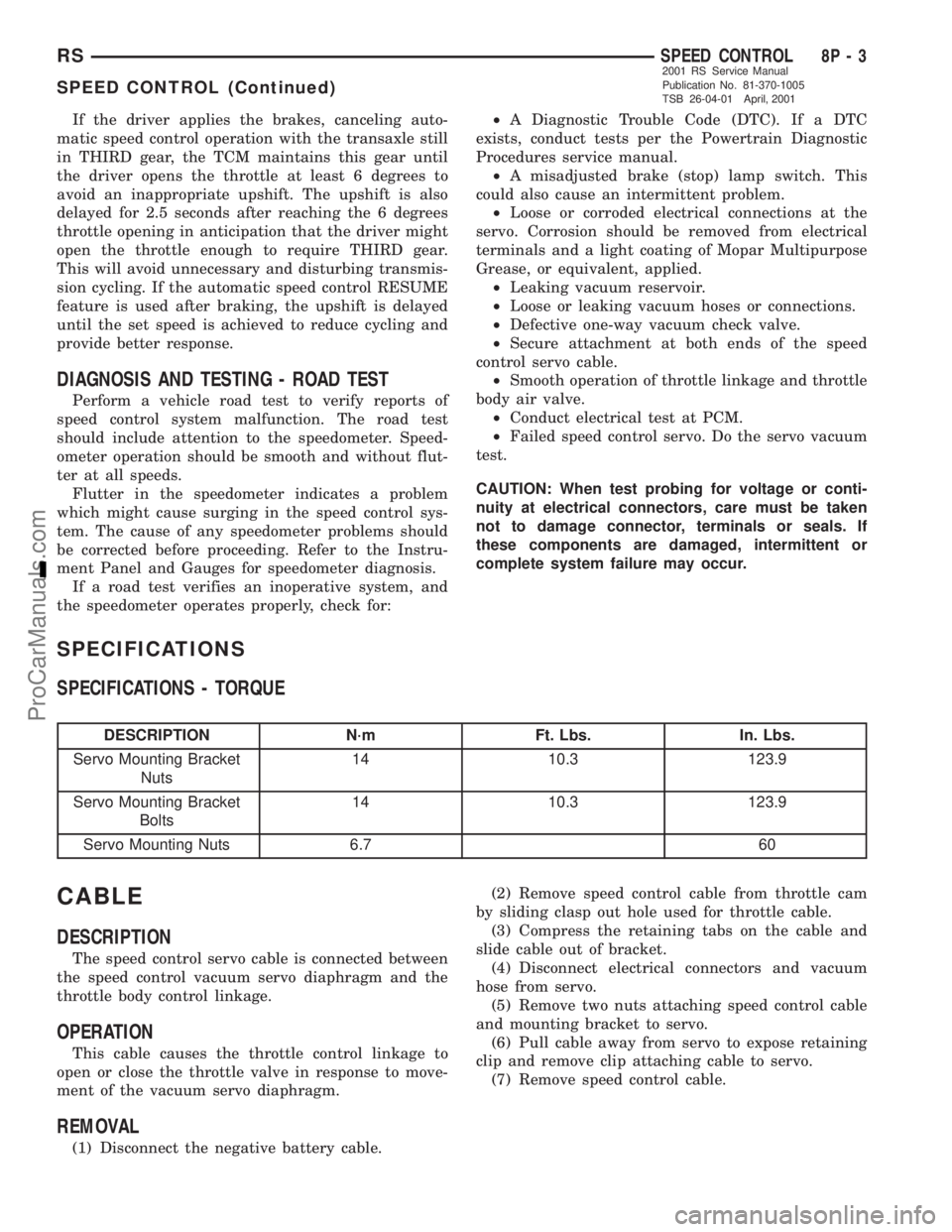
If the driver applies the brakes, canceling auto-
matic speed control operation with the transaxle still
in THIRD gear, the TCM maintains this gear until
the driver opens the throttle at least 6 degrees to
avoid an inappropriate upshift. The upshift is also
delayed for 2.5 seconds after reaching the 6 degrees
throttle opening in anticipation that the driver might
open the throttle enough to require THIRD gear.
This will avoid unnecessary and disturbing transmis-
sion cycling. If the automatic speed control RESUME
feature is used after braking, the upshift is delayed
until the set speed is achieved to reduce cycling and
provide better response.
DIAGNOSIS AND TESTING - ROAD TEST
Perform a vehicle road test to verify reports of
speed control system malfunction. The road test
should include attention to the speedometer. Speed-
ometer operation should be smooth and without flut-
ter at all speeds.
Flutter in the speedometer indicates a problem
which might cause surging in the speed control sys-
tem. The cause of any speedometer problems should
be corrected before proceeding. Refer to the Instru-
ment Panel and Gauges for speedometer diagnosis.
If a road test verifies an inoperative system, and
the speedometer operates properly, check for:²A Diagnostic Trouble Code (DTC). If a DTC
exists, conduct tests per the Powertrain Diagnostic
Procedures service manual.
²A misadjusted brake (stop) lamp switch. This
could also cause an intermittent problem.
²Loose or corroded electrical connections at the
servo. Corrosion should be removed from electrical
terminals and a light coating of Mopar Multipurpose
Grease, or equivalent, applied.
²Leaking vacuum reservoir.
²Loose or leaking vacuum hoses or connections.
²Defective one-way vacuum check valve.
²Secure attachment at both ends of the speed
control servo cable.
²Smooth operation of throttle linkage and throttle
body air valve.
²Conduct electrical test at PCM.
²Failed speed control servo. Do the servo vacuum
test.
CAUTION: When test probing for voltage or conti-
nuity at electrical connectors, care must be taken
not to damage connector, terminals or seals. If
these components are damaged, intermittent or
complete system failure may occur.
SPECIFICATIONS
SPECIFICATIONS - TORQUE
DESCRIPTION N´m Ft. Lbs. In. Lbs.
Servo Mounting Bracket
Nuts14 10.3 123.9
Servo Mounting Bracket
Bolts14 10.3 123.9
Servo Mounting Nuts 6.7 60
CABLE
DESCRIPTION
The speed control servo cable is connected between
the speed control vacuum servo diaphragm and the
throttle body control linkage.
OPERATION
This cable causes the throttle control linkage to
open or close the throttle valve in response to move-
ment of the vacuum servo diaphragm.
REMOVAL
(1) Disconnect the negative battery cable.(2) Remove speed control cable from throttle cam
by sliding clasp out hole used for throttle cable.
(3) Compress the retaining tabs on the cable and
slide cable out of bracket.
(4) Disconnect electrical connectors and vacuum
hose from servo.
(5) Remove two nuts attaching speed control cable
and mounting bracket to servo.
(6) Pull cable away from servo to expose retaining
clip and remove clip attaching cable to servo.
(7) Remove speed control cable.
RSSPEED CONTROL8P-3
SPEED CONTROL (Continued)
2001 RS Service Manual
Publication No. 81-370-1005
TSB 26-04-01 April, 2001
ProCarManuals.com
Page 618 of 2321
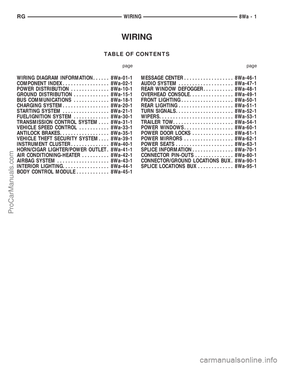
WIRING
TABLE OF CONTENTS
page page
WIRING DIAGRAM INFORMATION...... 8Wa-01-1
COMPONENT INDEX................. 8Wa-02-1
POWER DISTRIBUTION.............. 8Wa-10-1
GROUND DISTRIBUTION............. 8Wa-15-1
BUS COMMUNICATIONS............. 8Wa-18-1
CHARGING SYSTEM................. 8Wa-20-1
STARTING SYSTEM................. 8Wa-21-1
FUEL/IGNITION SYSTEM............. 8Wa-30-1
TRANSMISSION CONTROL SYSTEM.... 8Wa-31-1
VEHICLE SPEED CONTROL........... 8Wa-33-1
ANTILOCK BRAKES.................. 8Wa-35-1
VEHICLE THEFT SECURITY SYSTEM.... 8Wa-39-1
INSTRUMENT CLUSTER.............. 8Wa-40-1
HORN/CIGAR LIGHTER/POWER OUTLET . 8Wa-41-1
AIR CONDITIONING-HEATER.......... 8Wa-42-1
AIRBAG SYSTEM................... 8Wa-43-1
INTERIOR LIGHTING................. 8Wa-44-1
BODY CONTROL MODULE............ 8Wa-45-1MESSAGE CENTER.................. 8Wa-46-1
AUDIO SYSTEM.................... 8Wa-47-1
REAR WINDOW DEFOGGER........... 8Wa-48-1
OVERHEAD CONSOLE................ 8Wa-49-1
FRONT LIGHTING................... 8Wa-50-1
REAR LIGHTING.................... 8Wa-51-1
TURN SIGNALS..................... 8Wa-52-1
WIPERS........................... 8Wa-53-1
TRAILER TOW...................... 8Wa-54-1
POWER WINDOWS.................. 8Wa-60-1
POWER DOOR LOCKS............... 8Wa-61-1
POWER MIRRORS.................. 8Wa-62-1
POWER SEATS..................... 8Wa-63-1
SPLICE INFORMATION............... 8Wa-70-1
CONNECTOR PIN-OUTS.............. 8Wa-80-1
CONNECTOR/GROUND LOCATIONS BUX . 8Wa-90-1
SPLICE LOCATIONS BUX............. 8Wa-95-1 RGWIRING
8Wa-1
ProCarManuals.com