2001 DODGE TOWN AND COUNTRY battery
[x] Cancel search: batteryPage 419 of 2321
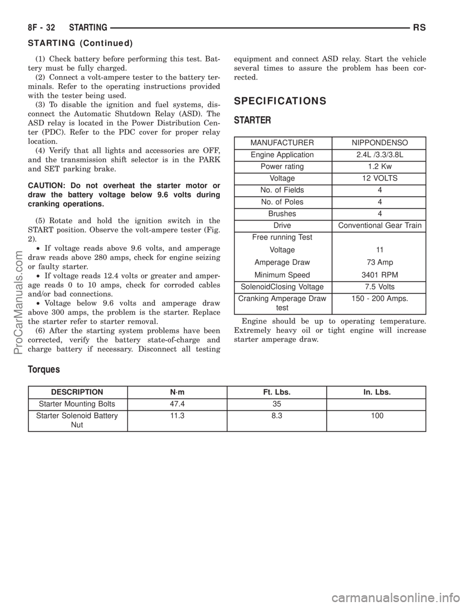
(1) Check battery before performing this test. Bat-
tery must be fully charged.
(2) Connect a volt-ampere tester to the battery ter-
minals. Refer to the operating instructions provided
with the tester being used.
(3) To disable the ignition and fuel systems, dis-
connect the Automatic Shutdown Relay (ASD). The
ASD relay is located in the Power Distribution Cen-
ter (PDC). Refer to the PDC cover for proper relay
location.
(4) Verify that all lights and accessories are OFF,
and the transmission shift selector is in the PARK
and SET parking brake.
CAUTION: Do not overheat the starter motor or
draw the battery voltage below 9.6 volts during
cranking operations.
(5) Rotate and hold the ignition switch in the
START position. Observe the volt-ampere tester (Fig.
2).
²If voltage reads above 9.6 volts, and amperage
draw reads above 280 amps, check for engine seizing
or faulty starter.
²If voltage reads 12.4 volts or greater and amper-
age reads 0 to 10 amps, check for corroded cables
and/or bad connections.
²Voltage below 9.6 volts and amperage draw
above 300 amps, the problem is the starter. Replace
the starter refer to starter removal.
(6) After the starting system problems have been
corrected, verify the battery state-of-charge and
charge battery if necessary. Disconnect all testingequipment and connect ASD relay. Start the vehicle
several times to assure the problem has been cor-
rected.
SPECIFICATIONS
STARTER
MANUFACTURER NIPPONDENSO
Engine Application 2.4L /3.3/3.8L
Power rating 1.2 Kw
Voltage 12 VOLTS
No. of Fields 4
No. of Poles 4
Brushes 4
Drive Conventional Gear Train
Free running Test
Voltage 11
Amperage Draw 73 Amp
Minimum Speed 3401 RPM
SolenoidClosing Voltage 7.5 Volts
Cranking Amperage Draw
test150 - 200 Amps.
Engine should be up to operating temperature.
Extremely heavy oil or tight engine will increase
starter amperage draw.
Torques
DESCRIPTION N´m Ft. Lbs. In. Lbs.
Starter Mounting Bolts 47.4 35
Starter Solenoid Battery
Nut11.3 8.3 100
8F - 32 STARTINGRS
STARTING (Continued)
ProCarManuals.com
Page 420 of 2321
STARTER MOTOR
REMOVAL - 2.4L
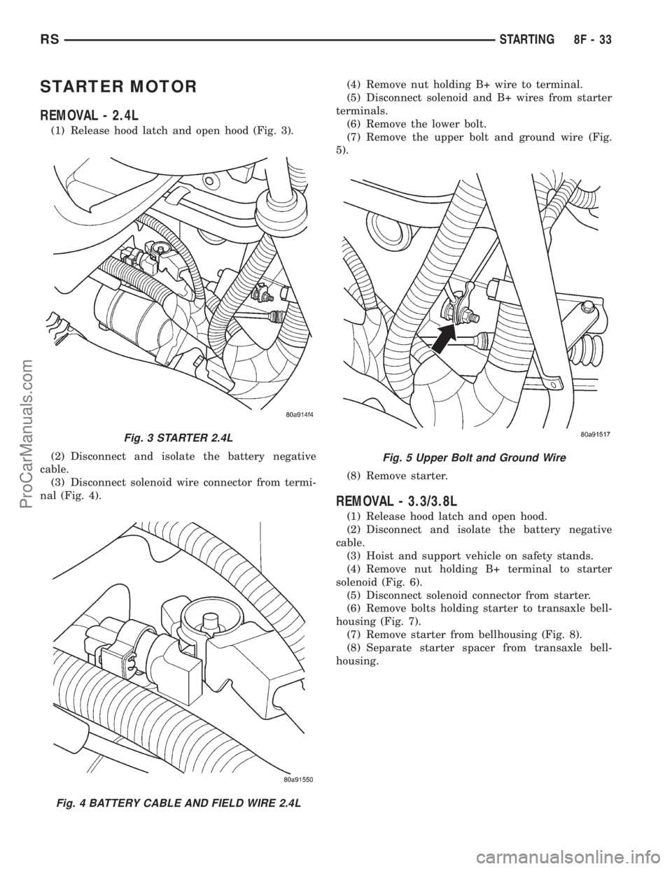
(1) Release hood latch and open hood (Fig. 3).
(2) Disconnect and isolate the battery negative
cable.
(3) Disconnect solenoid wire connector from termi-
nal (Fig. 4).(4) Remove nut holding B+ wire to terminal.
(5) Disconnect solenoid and B+ wires from starter
terminals.
(6) Remove the lower bolt.
(7) Remove the upper bolt and ground wire (Fig.
5).
(8) Remove starter.
REMOVAL - 3.3/3.8L
(1) Release hood latch and open hood.
(2) Disconnect and isolate the battery negative
cable.
(3) Hoist and support vehicle on safety stands.
(4) Remove nut holding B+ terminal to starter
solenoid (Fig. 6).
(5) Disconnect solenoid connector from starter.
(6) Remove bolts holding starter to transaxle bell-
housing (Fig. 7).
(7) Remove starter from bellhousing (Fig. 8).
(8) Separate starter spacer from transaxle bell-
housing.
Fig. 3 STARTER 2.4L
Fig. 4 BATTERY CABLE AND FIELD WIRE 2.4L
Fig. 5 Upper Bolt and Ground Wire
RSSTARTING8F-33
ProCarManuals.com
Page 421 of 2321
INSTALLATION - 2.4L
(1) Place starter in position on vehicle.
(2) Install the lower bolts to hold starter to tran-
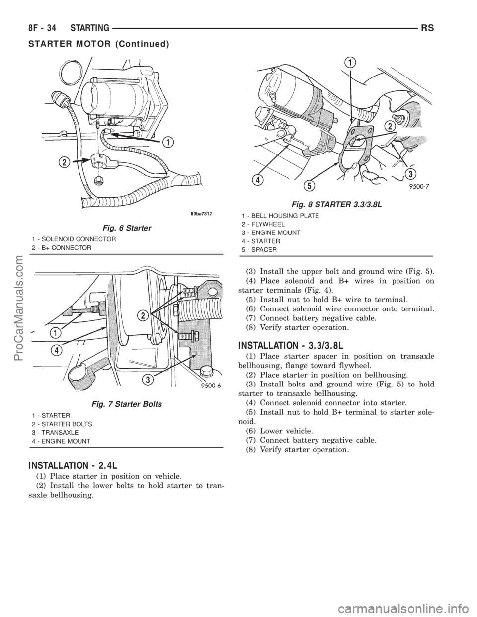
saxle bellhousing.(3) Install the upper bolt and ground wire (Fig. 5).
(4) Place solenoid and B+ wires in position on
starter terminals (Fig. 4).
(5) Install nut to hold B+ wire to terminal.
(6) Connect solenoid wire connector onto terminal.
(7) Connect battery negative cable.
(8) Verify starter operation.
INSTALLATION - 3.3/3.8L
(1) Place starter spacer in position on transaxle
bellhousing, flange toward flywheel.
(2) Place starter in position on bellhousing.
(3) Install bolts and ground wire (Fig. 5) to hold
starter to transaxle bellhousing.
(4) Connect solenoid connector into starter.
(5) Install nut to hold B+ terminal to starter sole-
noid.
(6) Lower vehicle.
(7) Connect battery negative cable.
(8) Verify starter operation.
Fig. 6 Starter
1 - SOLENOID CONNECTOR
2 - B+ CONNECTOR
Fig. 7 Starter Bolts
1-STARTER
2 - STARTER BOLTS
3 - TRANSAXLE
4 - ENGINE MOUNT
Fig. 8 STARTER 3.3/3.8L
1 - BELL HOUSING PLATE
2 - FLYWHEEL
3 - ENGINE MOUNT
4-STARTER
5 - SPACER
8F - 34 STARTINGRS
STARTER MOTOR (Continued)
ProCarManuals.com
Page 422 of 2321
ENGINE SYSTEMS
TABLE OF CONTENTS
page page
BATTERY SYSTEM - RG ONLY................ 1
CHARGING............................... 5STARTING................................ 7
BATTERY SYSTEM - RG ONLY
TABLE OF CONTENTS
page page
BATTERY
DESCRIPTION............................1
STANDARD PROCEDURE...................2
BATTERY..............................2BATTERY CHARGING....................3
BATTERY CABLES
REMOVAL...............................4
INSTALLATION............................4
BATTERY
DESCRIPTION
There are two different batteries available on this
model. Vehicles equipped with a diesel engine utilize
a spiral wound plate designed battery with recombi-
nation technology. This is a maintenance-free battery
that is capable of delivering more power than a con-
ventional battery. This additional power is required
by a diesel engine during cold cranking. Vehicles
equipped with a gasoline engine utilize a conven-
tional battery. Refer to the following information for
detailed differences and descriptions of these two bat-
teries.
SPIRAL PLATE BATTERY - DIESEL ENGINE
Spiral plate technology takes the elements of tradi-
tional batteries - lead and sulfuric acid - to the next
level. By tightly winding layers of spiral grids and
acid-permeated vitreous separators into cells, the
manufacturer has developed a battery with more
power and service life than conventional batteries the
same size. The spiral plate battery is completely, per-
manently sealed. Through gas recombination, hydro-
gen and oxygen within the battery are captured
during normal charging and reunited to form the
water within the electrolyte, eliminating the need to
add distilled water. Therefore, these batteries have
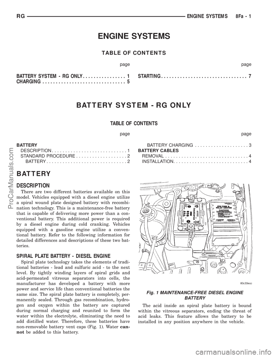
non-removable battery vent caps (Fig. 1). Watercan-
notbe added to this battery.The acid inside an spiral plate battery is bound
within the vitreous separators, ending the threat of
acid leaks. This feature allows the battery to be
installed in any position anywhere in the vehicle.
Fig. 1 MAINTENANCE-FREE DIESEL ENGINE
BATTERY
RGENGINE SYSTEMS8Fa-1
ProCarManuals.com
Page 423 of 2321
Spiral plate technology is the process by which the
plates holding the active material in the battery are
wound tightly in coils instead of hanging flat, like
conventional batteries. This design has a lower inter-
nal resistance and also increases the active material
surface area.
WARNING: NEVER EXCEED 14.4 VOLTS WHEN
CHARGING A SPIRAL PLATE BATTERY. PERSONAL
INJURY AND/OR BATTERY DAMAGE MAY RESULT.
Due to the maintanance-free design, distilled water
cannot be added to this battery. Therefore, if more
than 14.4 volts are used during the spiral plate bat-
tery charging process, water vapor can be exhausted
through the pressure-sensitive battery vents and lost
for good. This can permanently damage the spiral
plate battery. Never exceed 14.4 volts when charging
a spiral plate battery. Personal injury and/or battery
damage may result.
CONVENTIONAL BATTERY - GASOLINE ENGINE
Low-maintenance conventional batteries are used
on vehicles equipped with a gasoline engine, these
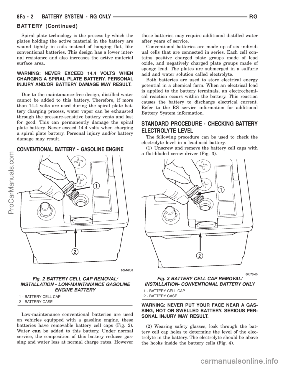
batteries have removable battery cell caps (Fig. 2).
Watercanbe added to this battery. Under normal
service, the composition of this battery reduces gas-
sing and water loss at normal charge rates. Howeverthese batteries may require additional distilled water
after years of service.
Conventional batteries are made up of six individ-
ual cells that are connected in series. Each cell con-
tains positive charged plate groups made of lead
oxide, and negatively charged plate groups made of
sponge lead. The plates are submerged in a sulfuric
acid and water solution called electrolyte.
Both batteries are used to store electrical energy
potential in a chemical form. When an electrical load
is applied to the battery terminals, an electrochemi-
cal reaction occurs within the battery. This reaction
causes the battery to discharge electrical current.
Refer to the RS service information for additional
Battery System information.
STANDARD PROCEDURE - CHECKING BATTERY
ELECTROLYTE LEVEL
The following procedure can be used to check the
electrolyte level in a lead-acid battery.
(1) Unscrew and remove the battery cell caps with
a flat-bladed screw driver (Fig. 3).
WARNING: NEVER PUT YOUR FACE NEAR A GAS-
SING, HOT OR SWELLED BATTERY. SERIOUS PER-
SONAL INJURY MAY RESULT.
(2) Wearing safety glasses, look through the bat-
tery cell cap holes to determine the level of the elec-
trolyte in the battery. The electrolyte should be above
the hooks inside the battery cells (Fig. 4).
Fig. 2 BATTERY CELL CAP REMOVAL/
INSTALLATION - LOW-MAINTANANCE GASOLINE
ENGINE BATTERY
1 - BATTERY CELL CAP
2 - BATTERY CASE
Fig. 3 BATTERY CELL CAP REMOVAL/
INSTALLATION- CONVENTIONAL BATTERY ONLY
1 - BATTERY CELL CAP
2 - BATTERY CASE
8Fa - 2 BATTERY SYSTEM - RG ONLYRG
BATTERY (Continued)
ProCarManuals.com
Page 424 of 2321
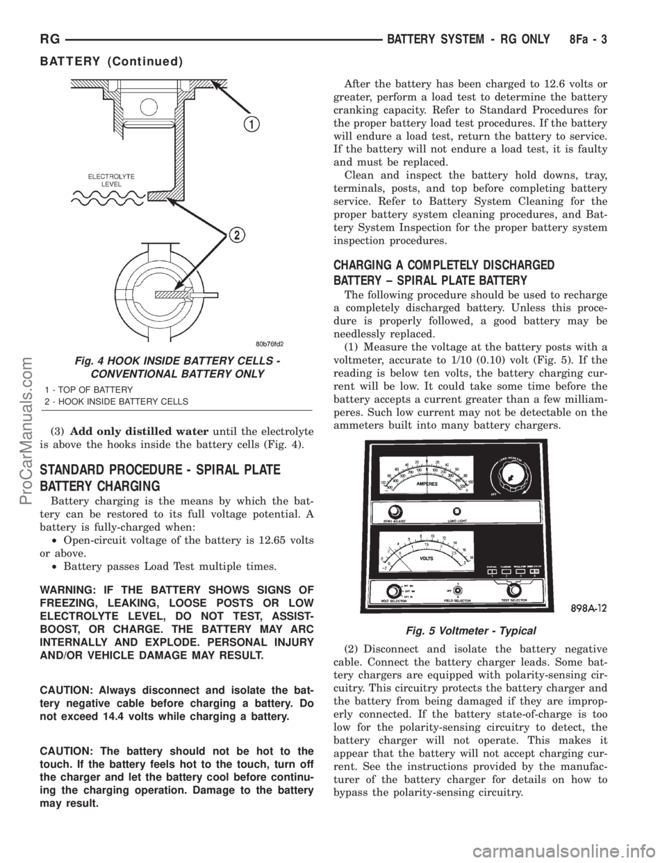
(3)Add only distilled wateruntil the electrolyte
is above the hooks inside the battery cells (Fig. 4).
STANDARD PROCEDURE - SPIRAL PLATE
BATTERY CHARGING
Battery charging is the means by which the bat-
tery can be restored to its full voltage potential. A
battery is fully-charged when:
²Open-circuit voltage of the battery is 12.65 volts
or above.
²Battery passes Load Test multiple times.
WARNING: IF THE BATTERY SHOWS SIGNS OF
FREEZING, LEAKING, LOOSE POSTS OR LOW
ELECTROLYTE LEVEL, DO NOT TEST, ASSIST-
BOOST, OR CHARGE. THE BATTERY MAY ARC
INTERNALLY AND EXPLODE. PERSONAL INJURY
AND/OR VEHICLE DAMAGE MAY RESULT.
CAUTION: Always disconnect and isolate the bat-
tery negative cable before charging a battery. Do
not exceed 14.4 volts while charging a battery.
CAUTION: The battery should not be hot to the
touch. If the battery feels hot to the touch, turn off
the charger and let the battery cool before continu-
ing the charging operation. Damage to the battery
may result.After the battery has been charged to 12.6 volts or
greater, perform a load test to determine the battery
cranking capacity. Refer to Standard Procedures for
the proper battery load test procedures. If the battery
will endure a load test, return the battery to service.
If the battery will not endure a load test, it is faulty
and must be replaced.
Clean and inspect the battery hold downs, tray,
terminals, posts, and top before completing battery
service. Refer to Battery System Cleaning for the
proper battery system cleaning procedures, and Bat-
tery System Inspection for the proper battery system
inspection procedures.
CHARGING A COMPLETELY DISCHARGED
BATTERY ± SPIRAL PLATE BATTERY
The following procedure should be used to recharge
a completely discharged battery. Unless this proce-
dure is properly followed, a good battery may be
needlessly replaced.
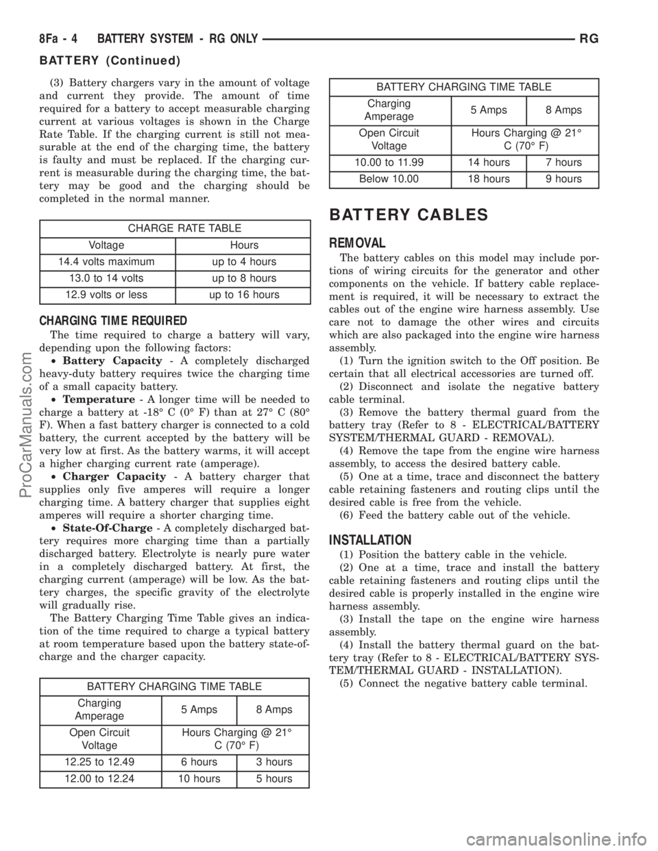
(1) Measure the voltage at the battery posts with a
voltmeter, accurate to 1/10 (0.10) volt (Fig. 5). If the
reading is below ten volts, the battery charging cur-
rent will be low. It could take some time before the
battery accepts a current greater than a few milliam-
peres. Such low current may not be detectable on the
ammeters built into many battery chargers.
(2) Disconnect and isolate the battery negative
cable. Connect the battery charger leads. Some bat-
tery chargers are equipped with polarity-sensing cir-
cuitry. This circuitry protects the battery charger and
the battery from being damaged if they are improp-
erly connected. If the battery state-of-charge is too
low for the polarity-sensing circuitry to detect, the
battery charger will not operate. This makes it
appear that the battery will not accept charging cur-
rent. See the instructions provided by the manufac-
turer of the battery charger for details on how to
bypass the polarity-sensing circuitry.
Fig. 4 HOOK INSIDE BATTERY CELLS -
CONVENTIONAL BATTERY ONLY
1 - TOP OF BATTERY
2 - HOOK INSIDE BATTERY CELLS
Fig. 5 Voltmeter - Typical
RGBATTERY SYSTEM - RG ONLY8Fa-3
BATTERY (Continued)
ProCarManuals.com
Page 425 of 2321
(3) Battery chargers vary in the amount of voltage
and current they provide. The amount of time
required for a battery to accept measurable charging
current at various voltages is shown in the Charge
Rate Table. If the charging current is still not mea-
surable at the end of the charging time, the battery
is faulty and must be replaced. If the charging cur-
rent is measurable during the charging time, the bat-
tery may be good and the charging should be
completed in the normal manner.
CHARGE RATE TABLE
Voltage Hours
14.4 volts maximum up to 4 hours
13.0 to 14 volts up to 8 hours
12.9 volts or less up to 16 hours
CHARGING TIME REQUIRED
The time required to charge a battery will vary,
depending upon the following factors:
²Battery Capacity- A completely discharged
heavy-duty battery requires twice the charging time
of a small capacity battery.
²Temperature- A longer time will be needed to
charge a battery at -18É C (0É F) than at 27É C (80É
F). When a fast battery charger is connected to a cold
battery, the current accepted by the battery will be
very low at first. As the battery warms, it will accept
a higher charging current rate (amperage).
²Charger Capacity- A battery charger that
supplies only five amperes will require a longer
charging time. A battery charger that supplies eight
amperes will require a shorter charging time.
²State-Of-Charge- A completely discharged bat-
tery requires more charging time than a partially
discharged battery. Electrolyte is nearly pure water
in a completely discharged battery. At first, the
charging current (amperage) will be low. As the bat-
tery charges, the specific gravity of the electrolyte
will gradually rise.
The Battery Charging Time Table gives an indica-
tion of the time required to charge a typical battery
at room temperature based upon the battery state-of-
charge and the charger capacity.
BATTERY CHARGING TIME TABLE
Charging
Amperage5 Amps 8 Amps
Open Circuit
VoltageHours Charging @ 21É
C (70É F)
12.25 to 12.49 6 hours 3 hours
12.00 to 12.24 10 hours 5 hours
BATTERY CHARGING TIME TABLE
Charging
Amperage5 Amps 8 Amps
Open Circuit
VoltageHours Charging @ 21É
C (70É F)
10.00 to 11.99 14 hours 7 hours
Below 10.00 18 hours 9 hours
BATTERY CABLES
REMOVAL
The battery cables on this model may include por-
tions of wiring circuits for the generator and other
components on the vehicle. If battery cable replace-
ment is required, it will be necessary to extract the
cables out of the engine wire harness assembly. Use
care not to damage the other wires and circuits
which are also packaged into the engine wire harness
assembly.
(1) Turn the ignition switch to the Off position. Be
certain that all electrical accessories are turned off.
(2) Disconnect and isolate the negative battery
cable terminal.
(3) Remove the battery thermal guard from the
battery tray (Refer to 8 - ELECTRICAL/BATTERY
SYSTEM/THERMAL GUARD - REMOVAL).
(4) Remove the tape from the engine wire harness
assembly, to access the desired battery cable.
(5) One at a time, trace and disconnect the battery
cable retaining fasteners and routing clips until the
desired cable is free from the vehicle.
(6) Feed the battery cable out of the vehicle.
INSTALLATION
(1) Position the battery cable in the vehicle.
(2) One at a time, trace and install the battery
cable retaining fasteners and routing clips until the
desired cable is properly installed in the engine wire
harness assembly.
(3) Install the tape on the engine wire harness
assembly.
(4) Install the battery thermal guard on the bat-
tery tray (Refer to 8 - ELECTRICAL/BATTERY SYS-
TEM/THERMAL GUARD - INSTALLATION).
(5) Connect the negative battery cable terminal.
8Fa - 4 BATTERY SYSTEM - RG ONLYRG
BATTERY (Continued)
ProCarManuals.com
Page 426 of 2321
CHARGING
TABLE OF CONTENTS
page page
GENERATOR
REMOVAL...............................5INSTALLATION............................6
GENERATOR
REMOVAL
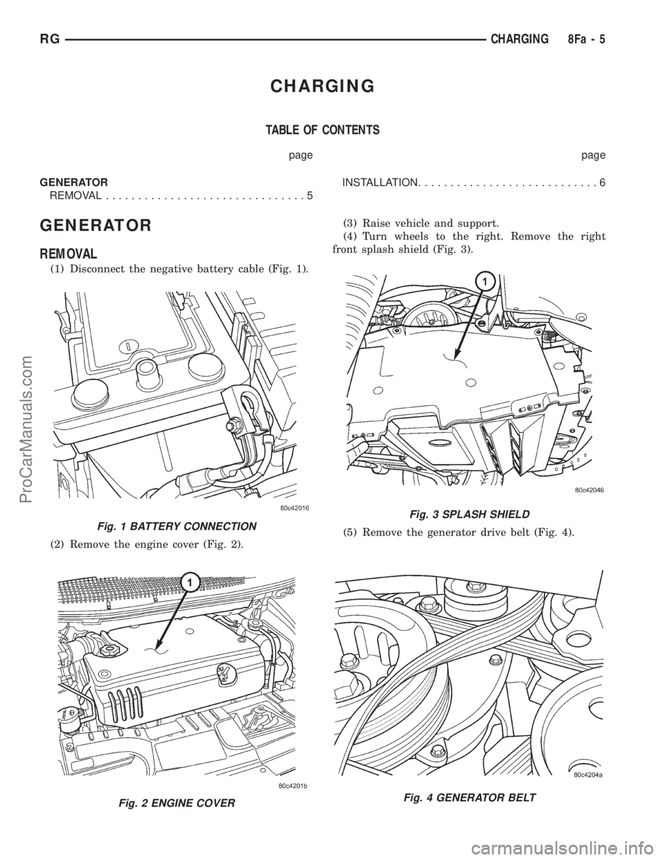
(1) Disconnect the negative battery cable (Fig. 1).
(2) Remove the engine cover (Fig. 2).(3) Raise vehicle and support.
(4) Turn wheels to the right. Remove the right
front splash shield (Fig. 3).
(5) Remove the generator drive belt (Fig. 4).
Fig. 1 BATTERY CONNECTION
Fig. 2 ENGINE COVER
Fig. 3 SPLASH SHIELD
Fig. 4 GENERATOR BELT
RGCHARGING8Fa-5
ProCarManuals.com