2001 DODGE TOWN AND COUNTRY battery
[x] Cancel search: batteryPage 454 of 2321

(4) Remove bolt holding sensor.
(5) Rotate sensor away from block.
(6) Pull sensor up out of the chain case cover.Do
not pull on the sensor lead.There is an O-ring on
the sensor case. The O-ring may make removal diffi-
cult. A light tap to top of sensor prior to removal may
reduce force needed for removal.
INSTALLATION - 2.4L
The target magnet has locating dowels that fit into
machined locating holes in the end of the camshaft
(Fig. 8).(1) Install target magnet in end of camshaft.
Tighten mounting screw to 3 N´m (30 in. lbs.) torque.
Over torqueing could cause cracks in magnet. If mag-
net cracks replace it.
(2) Install camshaft position sensor. Tighten sensor
mounting screws to 12.9 N´m (115 in. lbs.) torque.
(3) Carefully attach electrical connector to cam-
shaft position sensor. Installation at an angle may
damage the sensor pins.
(4) Connect the negative battery cable.
INSTALLATION - 3.3/3.8L
If the removed sensor is reinstalled, clean off
the old spacer on the sensor face. A NEW
SPACER must be attached to the face before
installation.Inspect O-ring for damage, replace if
necessary. If the sensor is being replaced, confirm
that the paper spacer is attached to the face and
O-ring is positioned in groove of the new sensor (Fig.
9).
(1) Apply a couple drops of clean engine oil to the
O-ring prior to installation.
(2) Install sensor in the chain case cover and
rotate into position.
(3) Push sensor down until contact is made with
the camshaft gear. While holding the sensor in this
position, install and tighten the retaining bolt 14
N´m (125 in. lbs.) torque.
(4) Connect camshaft position sensor electrical
connector to harness connector.
(5) Install the air box cover and inlet hose (Fig. 6).
(6) Connect the negative battery cable.
Fig. 7 CAMSHAFT POSITION SENSOR
Fig. 8 Target Magnet Installation
1 - LOCATING DOWELS
2 - LOCATING HOLES (2)
Fig. 9 Camshaft Position Sensor and Spacer
1 - ELECTRICAL CONNECTOR
2 - O-RING
3 - PAPER SPACER
RSIGNITION CONTROL8I-5
CAMSHAFT POSITION SENSOR (Continued)
ProCarManuals.com
Page 455 of 2321

IGNITION COIL
DESCRIPTION
The ignition coil assembly consists of 2 or 3 inde-
pendent coils molded together (Fig. 10) or (Fig. 11).
The coil assembly for the 3.3/3.8L is mounted on the
intake manifold. The coil assembly for the 2.4L is
mounted on the cylinder head cover. Spark plug
cables route to each cylinder from the coil.
OPERATION
The coil fires two spark plugs every power stroke.
One plug is the cylinder under compression, the
other cylinder fires on the exhaust stroke. The Pow-
ertrain Control Module (PCM) determines which of
the coils to charge and fire at the correct time.
The Auto Shutdown (ASD) relay provides battery
voltage to the ignition coil. The PCM provides a
ground contact (circuit) for energizing the coil. When
the PCM breaks the contact, the magnetic energy in
the coil transfers to the secondary causing the spark.
The PCM will de-energize the ASD relay if it does
not receive the crankshaft position sensor and cam-
shaft position sensor inputs. Refer to Auto Shutdown
(ASD) RelayÐPCM Output, in this section for relay
operation.
REMOVAL - 2.4L
The electronic ignition coil pack attaches directly
to the valve cover.
(1) Diconnect the negative battery cable.
(2) Disconnect electrical connector from coil pack
(3) Remove coil pack mounting bolts.(4) Remove coil pack and heat shield (Fig. 10).
REMOVAL - 3.3/3.8L
(1) Disconnect the negative battery cable.
(2) Remove the throttle and speed control cables
from clip.
(3) Remove 2 bolts from the Power steering reser-
voir to intake manifold.
(4) Loosen the lower nut for the power steering
reservoir from stud on ignition coil bracket.
(5) Reposition the Power steering reservoir (Fig.
12).
(6) Remove the ignition cables from the ignition
coil.
(7) Disconnect the electrical connector from the
ignition coil.
(8) Remove 2 nuts from the ignition coil studs.
(9) Remove 2 bolts from ignition coil, remove coil.
INSTALLATION - 2.4L
(1) Install ignition coil and heat shield to valve
cover and tighten bolts.
(2) Connect the electrical connector to the ignition
coil.
(3) Transfer spark plug cables to new coil pack.
The coil pack towers are numbered with the cylinder
identification. Be sure the ignition cables are fully
seated onto the towers.
(4) Connect the negative battery cable.
Fig. 10 IGNITION COIL - 2.4L
Fig. 11 IGNITION COIL - 3.3/3.8L
1 - IGNITION COIL
8I - 6 IGNITION CONTROLRS
ProCarManuals.com
Page 456 of 2321

INSTALLATION - 3.3/3.8L
(1) Install coil over studs on bracket.
(2) Install 2 bolts to ignition coil.
(3) Install 2 nuts to the ignition coil studs. Tighten
nuts and bolts.
(4) Connect the electrical connector to the ignition
coil.
(5) Install the ignition cables to the ignition coil.
(6) Reposition the Power steering reservoir. Slide
bracket over the mounting stud (Fig. 12).
(7) Install 2 bolts the Power steering reservoir to
intake manifold.
(8) Tighten the lower nut to stud on ignition coil
bracket.
(9) Install the throttle and speed control cables to
clip.
(10) Connect the negative battery cable.
KNOCK SENSOR
DESCRIPTION
The knock sensor threads into the cylinder block.
The knock sensor is designed to detect engine vibra-
tion that is caused by detonation.
OPERATION
When the knock sensor detects a knock in one of
the cylinders, it sends an input signal to the PCM. In
response, the PCM retards ignition timing for all cyl-
inders by a scheduled amount.Knock sensors contain a piezoelectric material
which constantly vibrates and sends an input voltage
(signal) to the PCM while the engine operates. As the
intensity of the crystal's vibration increases, the
knock sensor output voltage also increases.
The voltage signal produced by the knock sensor
increases with the amplitude of vibration. The PCM
receives as an input the knock sensor voltage signal.
If the signal rises above a predetermined level, the
PCM will store that value in memory and retard
ignition timing to reduce engine knock. If the knock
sensor voltage exceeds a preset value, the PCM
retards ignition timing for all cylinders. It is not a
selective cylinder retard.
The PCM ignores knock sensor input during engine
idle conditions. Once the engine speed exceeds a
specified value, knock retard is allowed.
Knock retard uses its own short term and long
term memory program.
Long term memory stores previous detonation
information in its battery-backed RAM. The maxi-
mum authority that long term memory has over tim-
ing retard can be calibrated.
Short term memory is allowed to retard timing up
to a preset amount under all operating conditions (as
long as rpm is above the minimum rpm) except WOT.
The PCM, using short term memory, can respond
quickly to retard timing when engine knock is
detected. Short term memory is lost any time the
ignition key is turned off.
NOTE: Over or under tightening affects knock sen-
sor performance, possibly causing improper spark
control.
REMOVAL - 2.4L
The knock sensor threads into the side of the cyl-
inder block in front of the starter (Fig. 13).
(1) Disconnect electrical connector from knock sen-
sor.
(2) Use a crow foot socket to remove the knock
sensors.
REMOVAL - 3.8L
The knock sensor threads into the side of the cyl-
inder block in the rear.
(1) Disconnect the negative battery cable.
(2) Raise vehicle and support.
(3) On All Wheel Drive vehicles remove the PTU
(Power Transfer Unit), refer to the Transmission sec-
tion for more information.
(4) Disconnect electrical connector from knock sen-
sor.
(5) Use a crow foot socket to remove the knock
sensor.
Fig. 12 IGNITION COIL BRACKET 3.3/3.8L
RSIGNITION CONTROL8I-7
IGNITION COIL (Continued)
ProCarManuals.com
Page 460 of 2321
INSTRUMENT CLUSTER
TABLE OF CONTENTS
page page
INSTRUMENT CLUSTER
DESCRIPTION............................1
OPERATION.............................1
DIAGNOSIS AND TESTING..................1
INSTRUMENT CLUSTER..................1
REMOVAL..............................11
INSTALLATION...........................11
CLUSTER LENS
REMOVAL..............................12INSTALLATION...........................12
MECHANICAL TRANSMISSION RANGE
INDICATOR
REMOVAL..............................12
INSTALLATION...........................12
RED BRAKE WARNING INDICATOR
DESCRIPTION...........................12
OPERATION.............................12
INSTRUMENT CLUSTER
DESCRIPTION
The instrumentation gauges are contained in a
subdial assembly within the instrument cluster. The
individual gauges are not serviceable. If one of the
cluster gauges becomes faulty, the entire cluster
would require replacement.
The mechanical instrument cluster with a tachom-
eter is equipped with a electronic vacuum fluorescent
transmission range indicator (PRND3L), odometer,
and trip odometer display.
The mechanical instrument cluster without a
tachometer is equipped with a cable operated trans-
mission range indicator (PRND21) and a vacuum
flourescent odometer display.
The instrument cluster is equipped with the follow-
ing warning lamps.
²Lift Gate Ajar
²Low Fuel Level
²Low Windshield Washer Fluid Level
²Cruise
²Battery Voltage
²Fasten Seat Belt
²Door Ajar
²Headlamp Out
²Coolant Temperature
²Anti-Lock Brake
²Brake
²Airbag
²Traction Control
²Autostick
OPERATION
Refer to the vehicle Owner's Manual for operation
instructions and conditions for the Instrument Clus-
ter Gauges.
DIAGNOSIS AND TESTING - SELF-
DIAGNOSTICS
The instrument clusters are equipped with a self
diagnostic test feature to help identify electronic
problems. Prior to any test, perform the Self-Diag-
nostic Test. The self diagnostic system displays
instrument cluster stored fault codes in the odometer
display, sweeps the gauges to the calibration points,
and bulb checks the warning indicators. When the
key is in the ON position with the engine not run-
ning, the MIL will remain illuminated for regulatory
purposes.
To activate the Self-Diagnostic program:
(1) With the ignition switch in the OFF position,
depress the TRIP ODOMETER RESET button.
(2) Continue to hold the TRIP ODOMETER
RESET button untilSofand a number (software ver-
sion number (i.e.Sof 3.2) appears in the odometer
window (about five seconds) then release the button.
If a fault code is present, the cluster will display it in
the odometer display. When all fault codes have been
displayed, the cluster will displayªendºin the odom-
eter display. Refer to the table to determine what
each trouble code means.
RSINSTRUMENT CLUSTER8J-1
ProCarManuals.com
Page 470 of 2321
CONDITION POSSIBLE CAUSES CORRECTION
INDICATOR DOES NOT
MAKE FULL TRAVEL (ªPº
< > ª1º).1. CABLE DISLODGED
FROM ITS PATH ON THE
INDICATOR BASE.1. VERIFY CORRECT ATTACHMENT OF INDICATOR
CABLE TO SHIFT LEVER PIN (UNDER HOOP OF
TRANS. SHIFT CABLE) AND CLIP ONTO THE
MOUNTING BRACKET.
2. INCORRECT
ATTACHMENT OF CABLE
TO SHIFT LEVER PIN.2. VERIFY INDICATOR TRAVEL BY PULLING ON
CABLE GENTLY OVER FULL TRAVEL RANGE. IF
THERE IS STILL A PROBLEM, REMOVE CLUSTER
TO ACCESS INDICATOR BASE AND CONFIRM
CABLE PATH.
REMOVAL
WITH ELECTRONIC TRANSMISSION RANGE
INDICATOR
(1) Disconnect and isolate the battery negative
cable.
(2) Remove Over Steering Column Bezel by lifting
it straight up with a firm pull.
(3) Remove the four cluster bezel attaching screws.
(4) Tilt the steering column in the full down posi-
tion.
(5) Pull rearward on the cluster bezel and remove.
(6) Remove the four screws holding instrument
cluster to instrument panel.
(7) Rotate top of cluster outward.
(8) Disconnect the cluster harness connector.
(9) Remove instrument cluster from instrument
panel.
WITH MECHANICAL TRANSMISSION RANGE
INDICATOR
(1) Disconnect and isolate the battery negative
cable.
(2) Remove the lower steering column cover. Refer
to Body, Instrument Panel, Lower Steering Column
Cover, Removal.
(3) Remove the plastic knee blocker reinforcement.
Refer to Body, Instrument Panel, Knee Blocker Rein-
forcement, Removal.
(4) Disconnect the transmission range indicator
cable end from shift lever by flexing the HOOP on
the transmission shift cable rearward and slip the
indicator cable loop off the lever pin.
(5) Disconnect the clip holding the indicator cable
to the mounting bracket.
(6) Remove Over Steering Column Bezel by lifting
it straight up with a firm pull.
(7) Remove the four bezel attaching screws.
(8) Tilt the steering column in the full down posi-
tion.
(9) Pull rearward on the cluster bezel and remove.
(10) Remove the four cluster attaching screws.
(11) Rotate top of the cluster rearward.(12) Disconnect the cluster harness connector.
(13) Remove the instrument cluster carefully while
guiding the range indicator cable and guide tube
through the opening to avoid any damage.
INSTALLATION
WITH ELECTRONIC TRANSMISSION RANGE
INDICATOR
(1) Connect the instrument cluster wire connector.
(2) Rotate top of cluster inward as placing into
instrument panel opening.
(3) Install the four screws holding instrument clus-
ter to instrument panel.
(4) Position cluster bezel into place.
(5) Install the four bezel attaching screws.
(6) Install the Over Steering Column Bezel by
firmly snapping into place.
(7) Connect the battery negative cable.
WITH MECHANICAL TRANSMISSION RANGE
INDICATOR
(1) Guide the range indicator cable and guide tube
through the opening of instrument panel.
(2) Connect the instrument cluster wire connector.
(3) Rotate top of cluster inward as placing into
instrument panel opening.
(4) Install the four screws holding instrument clus-
ter to instrument panel.
(5) Position cluster bezel into place.
(6) Install the four bezel attaching screws.
(7) Install the Over Steering Column Bezel by
firmly snapping into place.
(8) Connect the clip holding the indicator cable to
the mounting bracket.
(9) Connect the transmission range indicator cable
end to the shift lever by flexing the HOOP on the
transmission shift cable forward and slip the indica-
tor cable loop on the lever pin.
(10) Install the plastic knee blocker reinforcement.
Refer to Body, Instrument Panel, Knee Blocker Rein-
forcement, Installation.
RSINSTRUMENT CLUSTER8J-11
INSTRUMENT CLUSTER (Continued)
ProCarManuals.com
Page 471 of 2321
(11) Install the lower steering column cover. Refer
to Body, Instrument Panel, Lower Steering Column
Cover, Installation.
(12) Connect the battery negative cable.
CLUSTER LENS
REMOVAL
(1) Remove the instrument cluster. Refer to Elec-
trical, Instrument Cluster, Removal.
(2) Remove the screws holding the lens to the
instrument cluster.
(3) Press down on the snap features of the lens
and remove the lens from the cluster.
INSTALLATION
(1) Insert the lens snap features into the cluster.
(2) Install the screws holding the lens to the
instrument cluster.
(3) Install the instrument cluster. Refer to Electri-
cal, Instrument Cluster, Installation.
MECHANICAL TRANSMISSION
RANGE INDICATOR
REMOVAL
(1) Remove the instrument cluster and disconnect
the range indicator cable at both attaching points.
Refer to Electrical, Instrument Cluster, Removal.
(2) From the backside of the cluster, remove two
screws holding the mechanical transmission rangeindicator and then remove it fromt instrument clus-
ter.
INSTALLATION
(1) Insert the mechanical transmission range indi-
cator into the backside of the instrument cluster and
install the two screws.
(2) Install the instrument cluster. Refer to Electri-
cal, Instrument Cluster, Installation.
RED BRAKE WARNING
INDICATOR
DESCRIPTION
The red BRAKE warning indicator (lamp) is
located in the instrument panel cluster and is used to
indicate a low brake fluid condition or that the park-
ing brake is applied. In addition, the brake warning
indicator is turned on as a bulb check by the ignition
switch every time the ignition switch is placed in the
crank position.
OPERATION
The red BRAKE warning indicator (lamp) is sup-
plied a 12-volt ignition feed anytime the ignition
switch is on. The bulb is then illuminated by com-
pleting the ground circuit either through the switch
on the parking brake lever, the brake fluid level
switch in the master cylinder reservoir, or the igni-
tion switch when it is placed in the crank position.
8J - 12 INSTRUMENT CLUSTERRS
INSTRUMENT CLUSTER (Continued)
ProCarManuals.com
Page 476 of 2321
DAYTIME RUNNING LAMPS
Power is reduced using pulse-width modulation to
the high beams, where by the power is switched on
and off rapidly instead of remaining on continuously.
The duration and interval of the power pulses is pro-
grammed into the Front Control Module (FCM).
HEADLAMP SYSTEM
The headlamp system will default to headlamps
ON position when ignition switch is ON and when an
open or short circuit failure occurs on the headlamp
switch input. The system will return to normal oper-
ation when the open or short is repaired. A fault will
be reported by the BCM when a failure occurs on the
dimmer or headlamp switch input.
If the exterior lamps are ON and the headlamp
switch is in any position other than OFF or AUTO
and with the ignition switch OFF (LOCK) after 3
minutes the BCM sends a message via J1850 to the
FCM informing the FCM to turn off the headlamps,
park lamps and fog lamps. This feature prevents the
vehicle battery from being discharged when the vehi-
cle lights have been left ON.
HEADLAMP TIME DELAY SYSTEM
The headlamp time delay system is activated by
turning the headlamps ON (high or low beam) while
the engine is running, turning the ignition switch
OFF, and then turning the headlamp switch OFF
within 45 seconds. The system will not activate if
more than 45 seconds elapse between ignition switch
OFF and headlamp switch OFF. The BCM will allow
the headlamps to remain ON for 90 seconds (config-
urable) before they automatically turn off (If the key
is in the ignition during the headlamp time delay
mode, then both the headlamps and park lamps
(including panel dimming) will be ON). Refer to the
Owner's Manual for more information.
If the headlamp switch is in the Auto Headlamp
Position, the headlamps are ON due to the night sig-
nal from the CMTC and the ignition switch is in any
position other than run/start, the BCM shall enter a
90 second (configurable) Auto Headlamps time delay
mode. If the key is in the ignition during the head-
lamp time delay mode, then both the headlamps and
park lamps (including panel dimming) will be ON. If
the key is not in the ignition, then only the head-
lamps will be ON. The BCM will allow the head-
lamps to remain ON for 90 seconds before they
automatically turn OFF. Refer to the Owner's Man-
ual for more information.
LAMP OUTAGE
If one or more of the following lamps (Low and/or
High beams) are out, then a ªlamps outº indicator
located in the cluster will illuminate.
OPTICAL HORN/HIGH BEAMS
When the multifunction switch is pulled to the first
detent (optical horn) signal, the headlamps are ON,
key-in the ignition the BCM shall send a message via
J1850 to the FCM to turn on the headlamps drivers
to illuminate all four filaments (Low and High
beams). When the multifunction switch is pulled to
the second detent (high beam) signal and the head-
lamps are ON, the BCM shall send a message via
J1850 to the FCM to turn on the headlamps drivers.
The High Beams are illuminated and the Low Beams
and Fog Lamps (if ON) are extinguished. If the head-
lamps were in the high beam configuration when
power was removed from the headlamps, the head-
lamps will be configured as low beam the next time
they are activated.
DIAGNOSIS AND TESTING
WARNING: EYE PROTECTION SHOULD BE USED
WHEN SERVICING GLASS COMPONENTS. PER-
SONAL INJURY CAN RESULT.
CAUTION: Do not touch the glass of halogen bulbs
with fingers or other possibly oily surface, reduced
bulb life will result. Do not use bulbs other than
those indicated in the Bulb Application table. Dam-
age to lamp and/or Daytime Running Lamp Module
can result. Do not use fuses, circuit breakers or
relays having greater amperage value than indi-
cated on the fuse panel or in the Owners Manual.
When a vehicle experiences problems with the
headlamp system, verify the condition of the battery
connections, fuses, charging system, headlamp bulbs,
wire connectors, relay, high beam switch, dimmer
switch, and headlamp switch. Refer to the appropri-
ate wiring information. The wiring information
includes wiring diagrams, proper wire and connector
repair procedures, details of wire harness routing
and retention, connector pin-out information and
location views for the various wire harness connec-
tors, splices and grounds.
Each vehicle is equipped with various lamp assem-
blies. A good ground is necessary for proper lighting
operation. Grounding is provided by the lamp socket
when it comes in contact with the metal body, or
through a separate ground wire.
When changing lamp bulbs check the socket for
corrosion. If corrosion is present, clean it with a wire
brush.
When it is necessary to remove components to ser-
vice another, it should not be necessary to apply
excessive force or bend a component to remove it.
Before damaging a trim component, verify hidden
fasteners or captured edges are not holding the com-
ponent in place.
RSLAMPS/LIGHTING - EXTERIOR8L-3
LAMPS/LIGHTING - EXTERIOR (Continued)
ProCarManuals.com
Page 477 of 2321
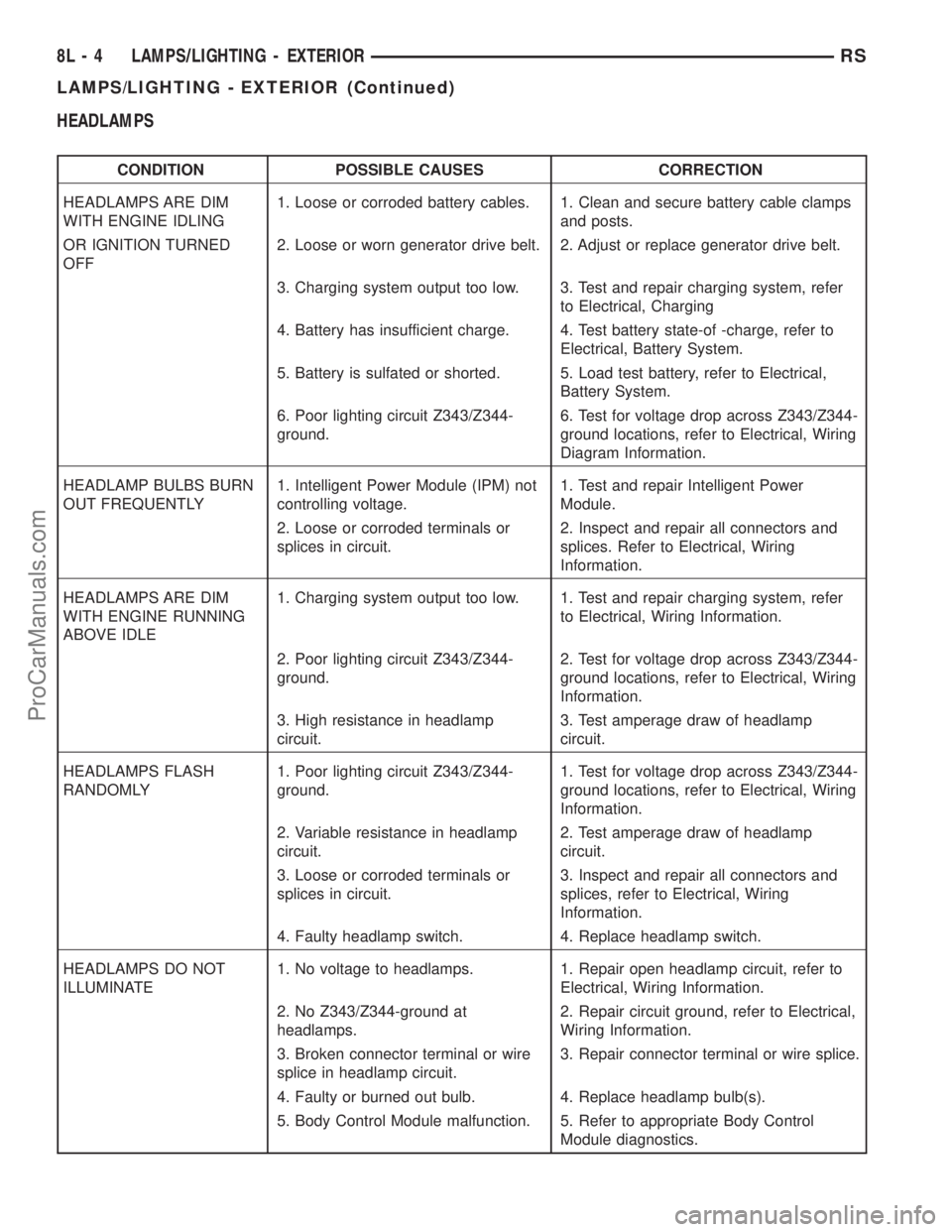
HEADLAMPS
CONDITION POSSIBLE CAUSES CORRECTION
HEADLAMPS ARE DIM
WITH ENGINE IDLING1. Loose or corroded battery cables. 1. Clean and secure battery cable clamps
and posts.
OR IGNITION TURNED
OFF2. Loose or worn generator drive belt. 2. Adjust or replace generator drive belt.
3. Charging system output too low. 3. Test and repair charging system, refer
to Electrical, Charging
4. Battery has insufficient charge. 4. Test battery state-of -charge, refer to
Electrical, Battery System.
5. Battery is sulfated or shorted. 5. Load test battery, refer to Electrical,
Battery System.
6. Poor lighting circuit Z343/Z344-
ground.6. Test for voltage drop across Z343/Z344-
ground locations, refer to Electrical, Wiring
Diagram Information.
HEADLAMP BULBS BURN
OUT FREQUENTLY1. Intelligent Power Module (IPM) not
controlling voltage.1. Test and repair Intelligent Power
Module.
2. Loose or corroded terminals or
splices in circuit.2. Inspect and repair all connectors and
splices. Refer to Electrical, Wiring
Information.
HEADLAMPS ARE DIM
WITH ENGINE RUNNING
ABOVE IDLE1. Charging system output too low. 1. Test and repair charging system, refer
to Electrical, Wiring Information.
2. Poor lighting circuit Z343/Z344-
ground.2. Test for voltage drop across Z343/Z344-
ground locations, refer to Electrical, Wiring
Information.
3. High resistance in headlamp
circuit.3. Test amperage draw of headlamp
circuit.
HEADLAMPS FLASH
RANDOMLY1. Poor lighting circuit Z343/Z344-
ground.1. Test for voltage drop across Z343/Z344-
ground locations, refer to Electrical, Wiring
Information.
2. Variable resistance in headlamp
circuit.2. Test amperage draw of headlamp
circuit.
3. Loose or corroded terminals or
splices in circuit.3. Inspect and repair all connectors and
splices, refer to Electrical, Wiring
Information.
4. Faulty headlamp switch. 4. Replace headlamp switch.
HEADLAMPS DO NOT
ILLUMINATE1. No voltage to headlamps. 1. Repair open headlamp circuit, refer to
Electrical, Wiring Information.
2. No Z343/Z344-ground at
headlamps.2. Repair circuit ground, refer to Electrical,
Wiring Information.
3. Broken connector terminal or wire
splice in headlamp circuit.3. Repair connector terminal or wire splice.
4. Faulty or burned out bulb. 4. Replace headlamp bulb(s).
5. Body Control Module malfunction. 5. Refer to appropriate Body Control
Module diagnostics.
8L - 4 LAMPS/LIGHTING - EXTERIORRS
LAMPS/LIGHTING - EXTERIOR (Continued)
ProCarManuals.com