2001 DODGE TOWN AND COUNTRY turn signal
[x] Cancel search: turn signalPage 1434 of 2321
PCM to vary the battery charging rate. System volt-
age will be higher at colder temperatures and is
gradually reduced at warmer temperatures.
The battery temperature information is also used
for OBD II diagnostics. Certain faults and OBD II
monitors are either enabled or disabled depending
upon the battery temperature sensor input (example:
disable purge, enable LDP). Most OBD II monitors
are disabled below 20ÉF.
MAP SENSOR
DESCRIPTION
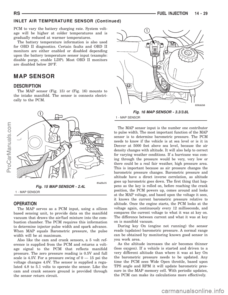
The MAP sensor (Fig. 15) or (Fig. 16) mounts to
the intake manifold. The sensor is connects electri-
cally to the PCM.
OPERATION
The MAP serves as a PCM input, using a silicon
based sensing unit, to provide data on the manifold
vacuum that draws the air/fuel mixture into the com-
bustion chamber. The PCM requires this information
to determine injector pulse width and spark advance.
When MAP equals Barometric pressure, the pulse
width will be at maximum.
Also like the cam and crank sensors, a 5 volt ref-
erence is supplied from the PCM and returns a volt-
age signal to the PCM that reflects manifold
pressure. The zero pressure reading is 0.5V and full
scale is 4.5V. For a pressure swing of0Ð15psithe
voltage changes 4.0V. The sensor is supplied a regu-
lated 4.8 to 5.1 volts to operate the sensor. Like the
cam and crank sensors ground is provided through
the sensor return circuit.
The MAP sensor input is the number one contributor
to pulse width. The most important function of the MAP
sensor is to determine barometric pressure. The PCM
needs to know if the vehicle is at sea level or is it in
Denver at 5000 feet above sea level, because the air
density changes with altitude. It will also help to correct
for varying weather conditions. If a hurricane was com-
ing through the pressure would be very, very low or
there could be a real fair weather, high pressure area.
This is important because as air pressure changes the
barometric pressure changes. Barometric pressure and
altitude have a direct inverse correlation, as altitude
goes up barometric goes down. The first thing that hap-
pens as the key is rolled on, before reaching the crank
position, the PCM powers up, comes around and looks
at the MAP voltage, and based upon the voltage it sees,
it knows the current barometric pressure relative to
altitude. Once the engine starts, the PCM looks at the
voltage again, continuously every 12 milliseconds, and
compares the current voltage to what it was at key on.
The difference between current and what it was at key
on is manifold vacuum.
During key On (engine not running) the sensor
reads (updates) barometric pressure. A normal range
can be obtained by monitoring known good sensor in
you work area.
As the altitude increases the air becomes thinner
(less oxygen). If a vehicle is started and driven to a
very different altitude than where it was at key On
the barometric pressure needs to be updated. Any
time the PCM sees Wide Open throttle, based upon
TPS angle and RPM it will update barometric pres-
sure in the MAP memory cell. With periodic updates,
the PCM can make its calculations more effectively.
Fig. 15 MAP SENSOR - 2.4L
1 - MAP SENSOR
Fig. 16 MAP SENSOR - 3.3/3.8L
1 - MAP SENSOR
RSFUEL INJECTION14-29
INLET AIR TEMPERATURE SENSOR (Continued)
ProCarManuals.com
Page 1453 of 2321
INSTALLATION
NOTE: Be sure the copper washer is installed on
end of injector before installing in cylinder head.
(1) Install fuel injector in cylinder head.
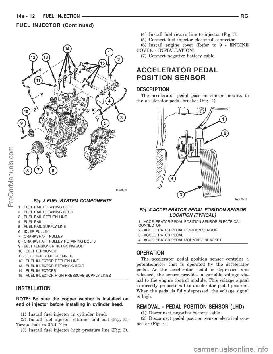
(2) Install fuel injector retainer and bolt (Fig. 3).
Torque bolt to 32.4 N´m.
(3) Install fuel injector high pressure line (Fig. 3).(4) Install fuel return line to injector (Fig. 3).
(5) Connect fuel injector electrical connector.
(6) Install engine cover (Refer to 9 - ENGINE
COVER - INSTALLATION).
(7) Connect negative battery cable.
ACCELERATOR PEDAL
POSITION SENSOR
DESCRIPTION
The accelerator pedal position sensor mounts to
the accelerator pedal bracket (Fig. 4).
OPERATION
The accelerator pedal position sensor contains a
potentiometer that is operated by the accelerator
pedal. As the accelerator pedal is depressed and
released, the sensor provides a variable voltage sig-
nal to the engine control module. This voltage signal
is directly proportional to accelerator pedal position.
When the pedal is fully depressed, the voltage signal
is high.
REMOVAL - PEDAL POSITION SENSOR (LHD)
(1) Disconnect negative battery cable.
(2) Disconnect pedal position sensor electrical con-
nector (Fig. 4).
Fig. 3 FUEL SYSTEM COMPONENTS
1 - FUEL RAIL RETAINING BOLT
2 - FUEL RAIL RETAINING STUD
3 - FUEL RAIL RETURN LINE
4 - FUEL RAIL
5 - FUEL RAIL SUPPLY LINE
6 - IDLER PULLEY
7 - CRANKSHAFT PULLEY
8 - CRANKSHAFT PULLEY RETAINING BOLTS
9 - BELT TENSIONER RETAINING BOLT
10 - BELT TENSIONER
11 - FUEL INJECTOR RETAINER
12 - FUEL INJECTOR RETURN LINE
13 - FUEL INJECTOR RETAINING BOLT
14 - FUEL INJECTORS
15 - FUEL INJECTOR HIGH PRESSURE SUPPLY LINESFig. 4 ACCELERATOR PEDAL POSITION SENSOR
LOCATION (TYPICAL)
1 - ACCELERATOR PEDAL POSITION SENSOR ELECTRICAL
CONNECTOR
2 - ACCELERATOR PEDAL POSITION SENSOR
3 - ACCELERATOR PEDAL
4 - ACCELERATOR PEDAL MOUNTING BRACKET
14a - 12 FUEL INJECTIONRG
FUEL INJECTOR (Continued)
ProCarManuals.com
Page 1467 of 2321
COLUMN
TABLE OF CONTENTS
page page
COLUMN
DESCRIPTION...........................10
WARNING..............................10
DIAGNOSIS AND TESTING.................12
STEERING COLUMN....................12
REMOVAL..............................12
INSTALLATION...........................13
SPECIFICATIONS........................14
KEY/LOCK CYLINDER
DESCRIPTION...........................14OPERATION.............................14
REMOVAL..............................14
INSTALLATION...........................14
GEAR SHIFT LEVER
REMOVAL..............................15
INSTALLATION...........................15
SHROUD
REMOVAL..............................16
INSTALLATION...........................16
COLUMN
DESCRIPTION - STEERING COLUMN
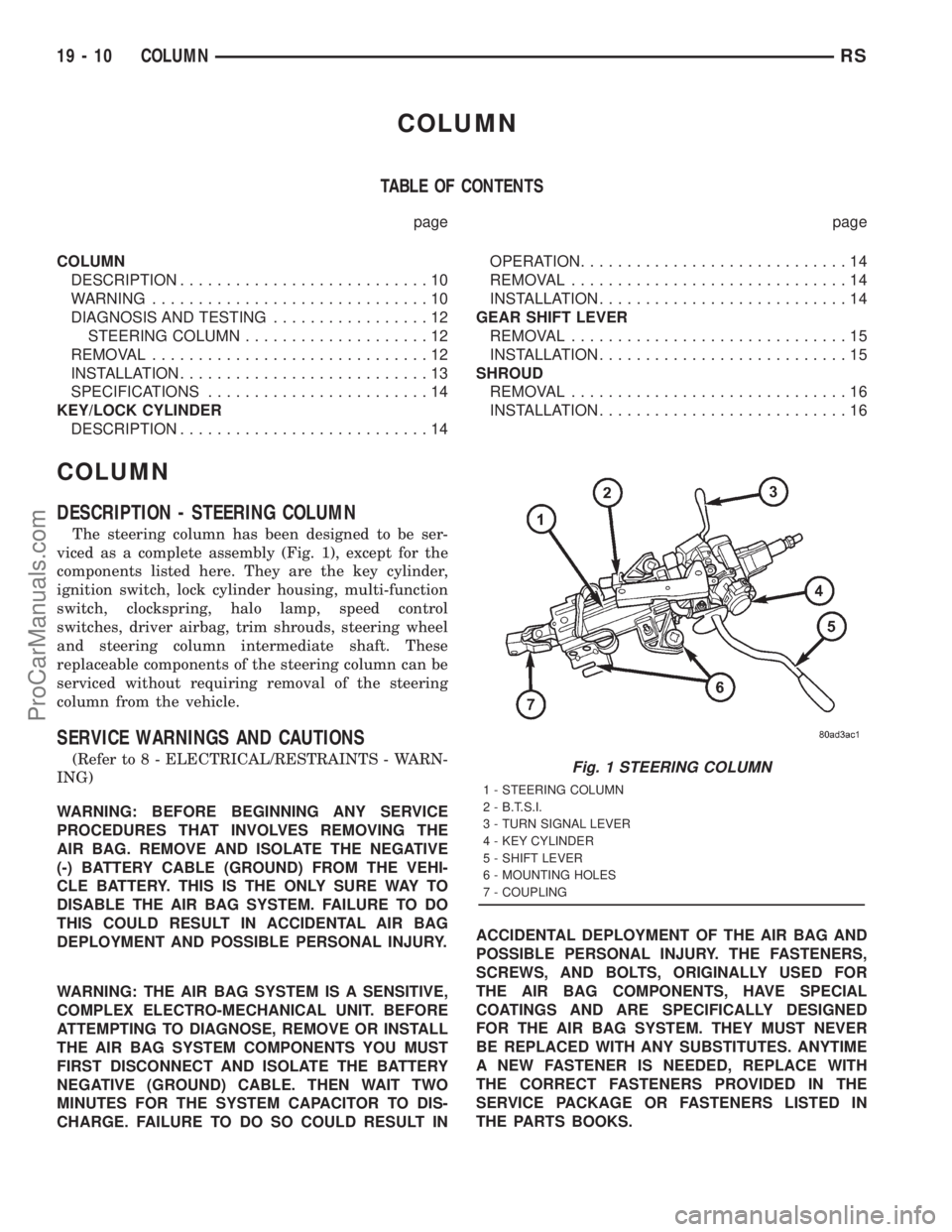
The steering column has been designed to be ser-
viced as a complete assembly (Fig. 1), except for the
components listed here. They are the key cylinder,
ignition switch, lock cylinder housing, multi-function
switch, clockspring, halo lamp, speed control
switches, driver airbag, trim shrouds, steering wheel
and steering column intermediate shaft. These
replaceable components of the steering column can be
serviced without requiring removal of the steering
column from the vehicle.
SERVICE WARNINGS AND CAUTIONS
(Refer to 8 - ELECTRICAL/RESTRAINTS - WARN-
ING)
WARNING: BEFORE BEGINNING ANY SERVICE
PROCEDURES THAT INVOLVES REMOVING THE
AIR BAG. REMOVE AND ISOLATE THE NEGATIVE
(-) BATTERY CABLE (GROUND) FROM THE VEHI-
CLE BATTERY. THIS IS THE ONLY SURE WAY TO
DISABLE THE AIR BAG SYSTEM. FAILURE TO DO
THIS COULD RESULT IN ACCIDENTAL AIR BAG
DEPLOYMENT AND POSSIBLE PERSONAL INJURY.
WARNING: THE AIR BAG SYSTEM IS A SENSITIVE,
COMPLEX ELECTRO-MECHANICAL UNIT. BEFORE
ATTEMPTING TO DIAGNOSE, REMOVE OR INSTALL
THE AIR BAG SYSTEM COMPONENTS YOU MUST
FIRST DISCONNECT AND ISOLATE THE BATTERY
NEGATIVE (GROUND) CABLE. THEN WAIT TWO
MINUTES FOR THE SYSTEM CAPACITOR TO DIS-
CHARGE. FAILURE TO DO SO COULD RESULT INACCIDENTAL DEPLOYMENT OF THE AIR BAG AND
POSSIBLE PERSONAL INJURY. THE FASTENERS,
SCREWS, AND BOLTS, ORIGINALLY USED FOR
THE AIR BAG COMPONENTS, HAVE SPECIAL
COATINGS AND ARE SPECIFICALLY DESIGNED
FOR THE AIR BAG SYSTEM. THEY MUST NEVER
BE REPLACED WITH ANY SUBSTITUTES. ANYTIME
A NEW FASTENER IS NEEDED, REPLACE WITH
THE CORRECT FASTENERS PROVIDED IN THE
SERVICE PACKAGE OR FASTENERS LISTED IN
THE PARTS BOOKS.Fig. 1 STEERING COLUMN
1 - STEERING COLUMN
2 - B.T.S.I.
3 - TURN SIGNAL LEVER
4 - KEY CYLINDER
5 - SHIFT LEVER
6 - MOUNTING HOLES
7 - COUPLING
19 - 10 COLUMNRS
ProCarManuals.com
Page 1600 of 2321
GEARSHIFT CABLE ADJUSTMENT
Lift and rotate the gearshift hand lever into the
park (P) gate position and remove the ignition key.
This confirms the shift lever is in the gated park (P)
position.
After confirming the park gate position, turn the
ignition switch . If the starter will operate, the park
gate position is correct. Move the shift lever into the
neutral (N) position. If the starter will operate in this
position, the linkage is properly adjusted. If the
starter fails to operate in either position, linkage
adjustment is required.
(1) Park the vehicle on level ground and set the
parking brake.
(2) Place the gearshift lever in park (P) gate posi-
tion and remove key.
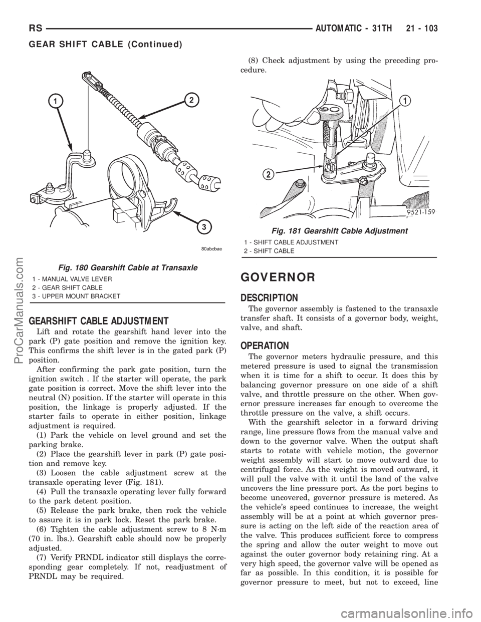
(3) Loosen the cable adjustment screw at the
transaxle operating lever (Fig. 181).
(4) Pull the transaxle operating lever fully forward
to the park detent position.
(5) Release the park brake, then rock the vehicle
to assure it is in park lock. Reset the park brake.
(6) Tighten the cable adjustment screw to 8 N´m
(70 in. lbs.). Gearshift cable should now be properly
adjusted.
(7) Verify PRNDL indicator still displays the corre-
sponding gear completely. If not, readjustment of
PRNDL may be required.(8) Check adjustment by using the preceding pro-
cedure.
GOVERNOR
DESCRIPTION
The governor assembly is fastened to the transaxle
transfer shaft. It consists of a governor body, weight,
valve, and shaft.
OPERATION
The governor meters hydraulic pressure, and this
metered pressure is used to signal the transmission
when it is time for a shift to occur. It does this by
balancing governor pressure on one side of a shift
valve, and throttle pressure on the other. When gov-
ernor pressure increases far enough to overcome the
throttle pressure on the valve, a shift occurs.
With the gearshift selector in a forward driving
range, line pressure flows from the manual valve and
down to the governor valve. When the output shaft
starts to rotate with vehicle motion, the governor
weight assembly will start to move outward due to
centrifugal force. As the weight is moved outward, it
will pull the valve with it until the land of the valve
uncovers the line pressure port. As the port begins to
become uncovered, governor pressure is metered. As
the vehicle's speed continues to increase, the weight
assembly will be at a point at which governor pres-
sure is acting on the left side of the reaction area of
the valve. This produces sufficient force to compress
the spring and allow the outer weight to move out
against the outer governor body retaining ring. At a
very high speed, the governor valve will be opened as
far as possible. In this condition, it is possible for
governor pressure to meet, but not to exceed, line
Fig. 180 Gearshift Cable at Transaxle
1 - MANUAL VALVE LEVER
2 - GEAR SHIFT CABLE
3 - UPPER MOUNT BRACKET
Fig. 181 Gearshift Cable Adjustment
1 - SHIFT CABLE ADJUSTMENT
2 - SHIFT CABLE
RSAUTOMATIC - 31TH21 - 103
GEAR SHIFT CABLE (Continued)
ProCarManuals.com
Page 1730 of 2321
OPERATION
The function of an accumulator is to cushion the
application of a frictional clutch element. When pres-
surized fluid is applied to a clutch circuit, the appli-
cation force is dampened by fluid collecting in the
respective accumulator chamber against the piston
and spring(s). The intended result is a smooth, firm
clutch application.
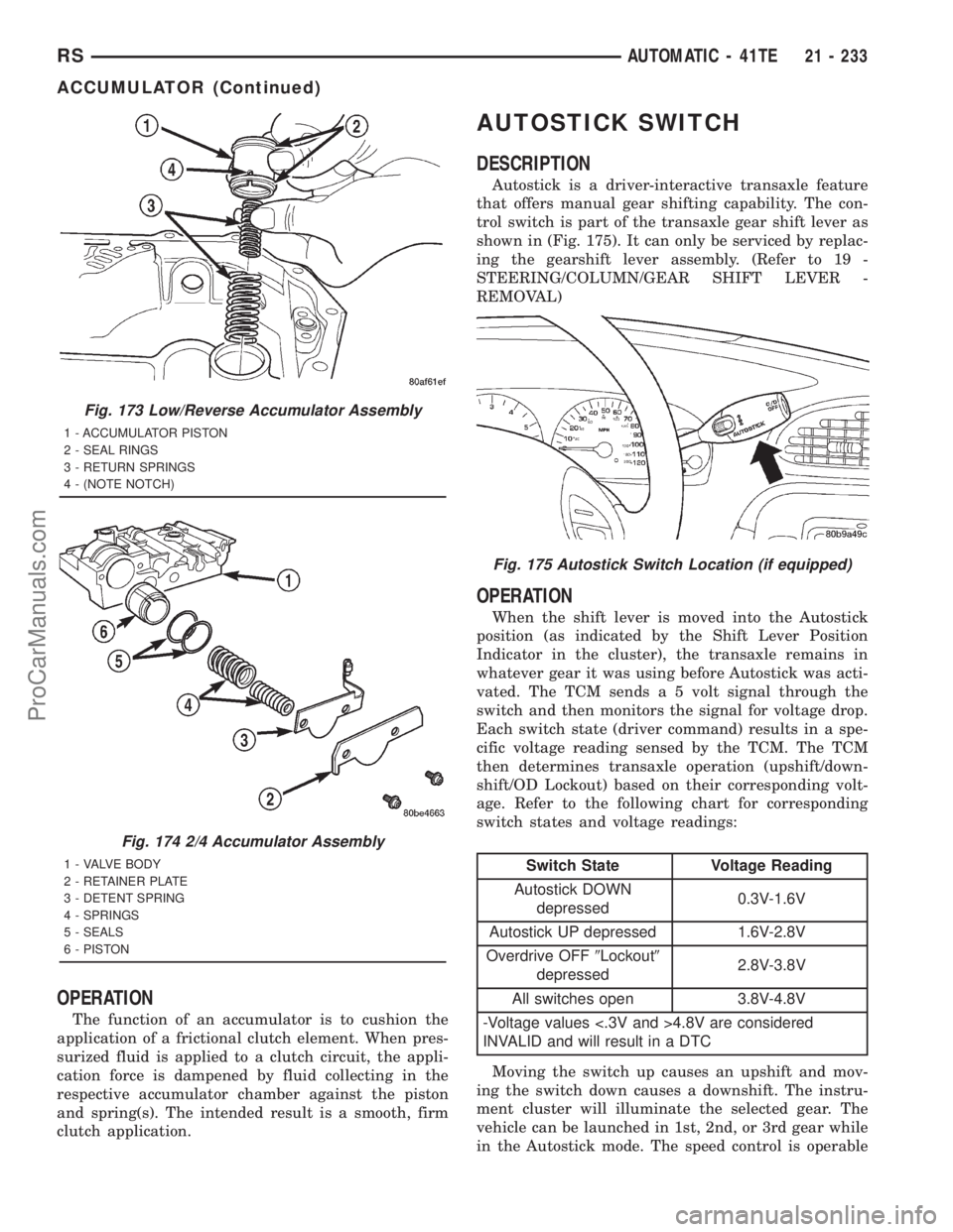
AUTOSTICK SWITCH
DESCRIPTION
Autostick is a driver-interactive transaxle feature
that offers manual gear shifting capability. The con-
trol switch is part of the transaxle gear shift lever as
shown in (Fig. 175). It can only be serviced by replac-
ing the gearshift lever assembly. (Refer to 19 -
STEERING/COLUMN/GEAR SHIFT LEVER -
REMOVAL)
OPERATION
When the shift lever is moved into the Autostick
position (as indicated by the Shift Lever Position
Indicator in the cluster), the transaxle remains in
whatever gear it was using before Autostick was acti-
vated. The TCM sends a 5 volt signal through the
switch and then monitors the signal for voltage drop.
Each switch state (driver command) results in a spe-
cific voltage reading sensed by the TCM. The TCM
then determines transaxle operation (upshift/down-
shift/OD Lockout) based on their corresponding volt-
age. Refer to the following chart for corresponding
switch states and voltage readings:
Switch State Voltage Reading
Autostick DOWN
depressed0.3V-1.6V
Autostick UP depressed 1.6V-2.8V
Overdrive OFF9Lockout9
depressed2.8V-3.8V
All switches open 3.8V-4.8V
-Voltage values <.3V and >4.8V are considered
INVALID and will result in a DTC
Moving the switch up causes an upshift and mov-
ing the switch down causes a downshift. The instru-
ment cluster will illuminate the selected gear. The
vehicle can be launched in 1st, 2nd, or 3rd gear while
in the Autostick mode. The speed control is operable
Fig. 173 Low/Reverse Accumulator Assembly
1 - ACCUMULATOR PISTON
2 - SEAL RINGS
3 - RETURN SPRINGS
4 - (NOTE NOTCH)
Fig. 174 2/4 Accumulator Assembly
1 - VALVE BODY
2 - RETAINER PLATE
3 - DETENT SPRING
4 - SPRINGS
5 - SEALS
6 - PISTON
Fig. 175 Autostick Switch Location (if equipped)
RSAUTOMATIC - 41TE21 - 233
ACCUMULATOR (Continued)
ProCarManuals.com
Page 1777 of 2321
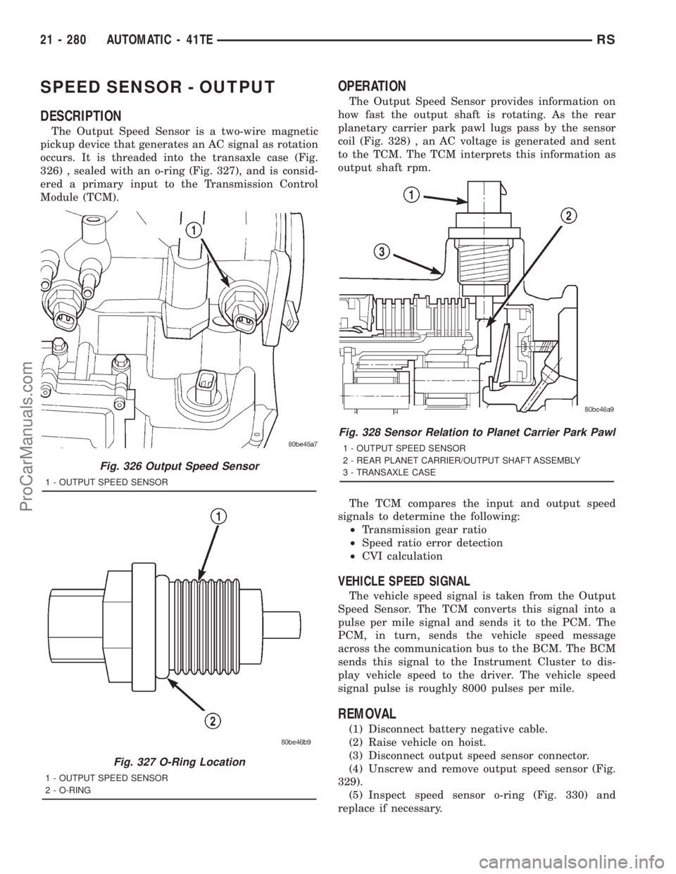
SPEED SENSOR - OUTPUT
DESCRIPTION
The Output Speed Sensor is a two-wire magnetic
pickup device that generates an AC signal as rotation
occurs. It is threaded into the transaxle case (Fig.
326) , sealed with an o-ring (Fig. 327), and is consid-
ered a primary input to the Transmission Control
Module (TCM).
OPERATION
The Output Speed Sensor provides information on
how fast the output shaft is rotating. As the rear
planetary carrier park pawl lugs pass by the sensor
coil (Fig. 328) , an AC voltage is generated and sent
to the TCM. The TCM interprets this information as
output shaft rpm.
The TCM compares the input and output speed
signals to determine the following:
²Transmission gear ratio
²Speed ratio error detection
²CVI calculation
VEHICLE SPEED SIGNAL
The vehicle speed signal is taken from the Output
Speed Sensor. The TCM converts this signal into a
pulse per mile signal and sends it to the PCM. The
PCM, in turn, sends the vehicle speed message
across the communication bus to the BCM. The BCM
sends this signal to the Instrument Cluster to dis-
play vehicle speed to the driver. The vehicle speed
signal pulse is roughly 8000 pulses per mile.
REMOVAL
(1) Disconnect battery negative cable.
(2) Raise vehicle on hoist.
(3) Disconnect output speed sensor connector.
(4) Unscrew and remove output speed sensor (Fig.
329).
(5) Inspect speed sensor o-ring (Fig. 330) and
replace if necessary.
Fig. 326 Output Speed Sensor
1 - OUTPUT SPEED SENSOR
Fig. 327 O-Ring Location
1 - OUTPUT SPEED SENSOR
2 - O-RING
Fig. 328 Sensor Relation to Planet Carrier Park Pawl
1 - OUTPUT SPEED SENSOR
2 - REAR PLANET CARRIER/OUTPUT SHAFT ASSEMBLY
3 - TRANSAXLE CASE
21 - 280 AUTOMATIC - 41TERS
ProCarManuals.com
Page 2173 of 2321
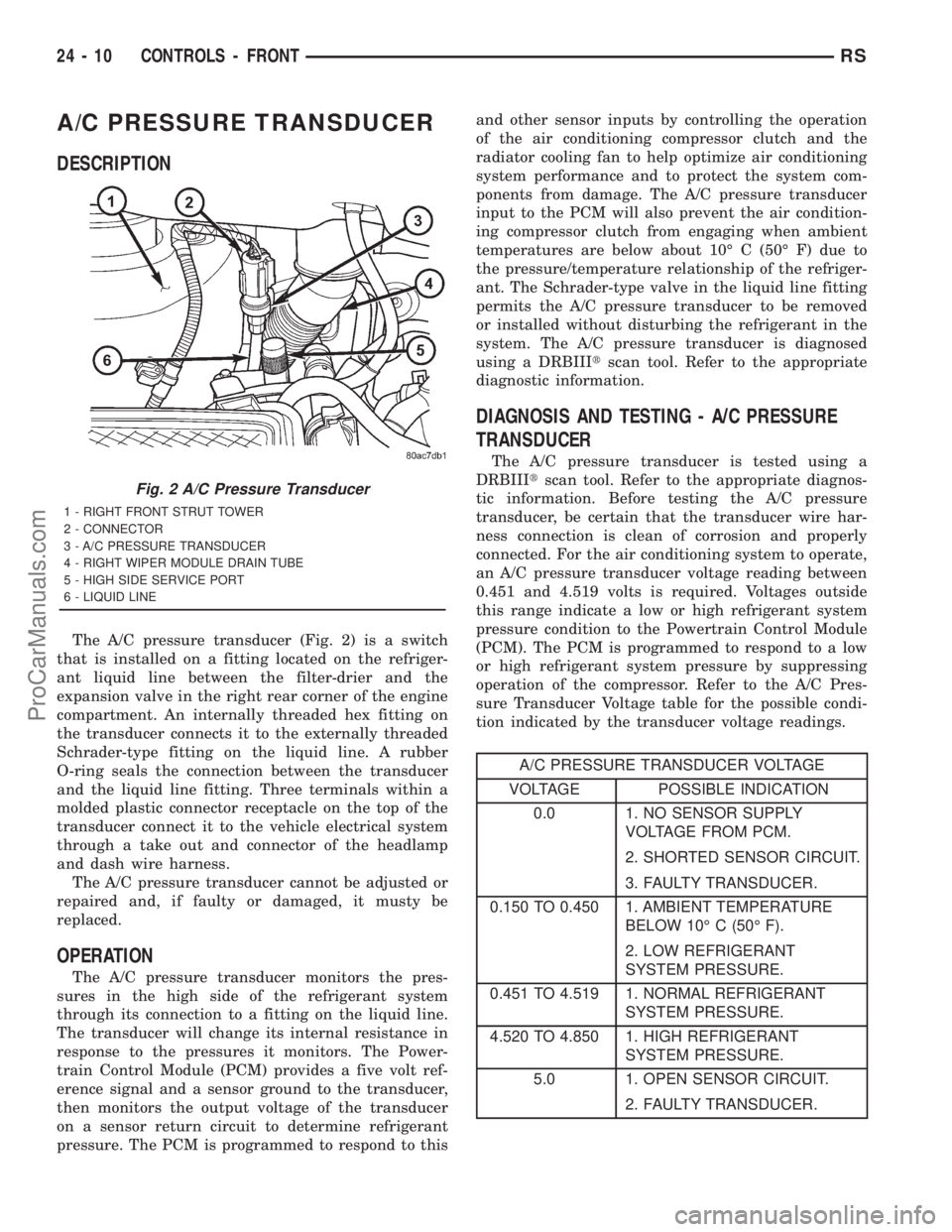
A/C PRESSURE TRANSDUCER
DESCRIPTION
The A/C pressure transducer (Fig. 2) is a switch
that is installed on a fitting located on the refriger-
ant liquid line between the filter-drier and the
expansion valve in the right rear corner of the engine
compartment. An internally threaded hex fitting on
the transducer connects it to the externally threaded
Schrader-type fitting on the liquid line. A rubber
O-ring seals the connection between the transducer
and the liquid line fitting. Three terminals within a
molded plastic connector receptacle on the top of the
transducer connect it to the vehicle electrical system
through a take out and connector of the headlamp
and dash wire harness.
The A/C pressure transducer cannot be adjusted or
repaired and, if faulty or damaged, it musty be
replaced.
OPERATION
The A/C pressure transducer monitors the pres-
sures in the high side of the refrigerant system
through its connection to a fitting on the liquid line.
The transducer will change its internal resistance in
response to the pressures it monitors. The Power-
train Control Module (PCM) provides a five volt ref-
erence signal and a sensor ground to the transducer,
then monitors the output voltage of the transducer
on a sensor return circuit to determine refrigerant
pressure. The PCM is programmed to respond to thisand other sensor inputs by controlling the operation
of the air conditioning compressor clutch and the
radiator cooling fan to help optimize air conditioning
system performance and to protect the system com-
ponents from damage. The A/C pressure transducer
input to the PCM will also prevent the air condition-
ing compressor clutch from engaging when ambient
temperatures are below about 10É C (50É F) due to
the pressure/temperature relationship of the refriger-
ant. The Schrader-type valve in the liquid line fitting
permits the A/C pressure transducer to be removed
or installed without disturbing the refrigerant in the
system. The A/C pressure transducer is diagnosed
using a DRBIIItscan tool. Refer to the appropriate
diagnostic information.
DIAGNOSIS AND TESTING - A/C PRESSURE
TRANSDUCER
The A/C pressure transducer is tested using a
DRBIIItscan tool. Refer to the appropriate diagnos-
tic information. Before testing the A/C pressure
transducer, be certain that the transducer wire har-
ness connection is clean of corrosion and properly
connected. For the air conditioning system to operate,
an A/C pressure transducer voltage reading between
0.451 and 4.519 volts is required. Voltages outside
this range indicate a low or high refrigerant system
pressure condition to the Powertrain Control Module
(PCM). The PCM is programmed to respond to a low
or high refrigerant system pressure by suppressing
operation of the compressor. Refer to the A/C Pres-
sure Transducer Voltage table for the possible condi-
tion indicated by the transducer voltage readings.
A/C PRESSURE TRANSDUCER VOLTAGE
VOLTAGE POSSIBLE INDICATION
0.0 1. NO SENSOR SUPPLY
VOLTAGE FROM PCM.
2. SHORTED SENSOR CIRCUIT.
3. FAULTY TRANSDUCER.
0.150 TO 0.450 1. AMBIENT TEMPERATURE
BELOW 10É C (50É F).
2. LOW REFRIGERANT
SYSTEM PRESSURE.
0.451 TO 4.519 1. NORMAL REFRIGERANT
SYSTEM PRESSURE.
4.520 TO 4.850 1. HIGH REFRIGERANT
SYSTEM PRESSURE.
5.0 1. OPEN SENSOR CIRCUIT.
2. FAULTY TRANSDUCER.
Fig. 2 A/C Pressure Transducer
1 - RIGHT FRONT STRUT TOWER
2 - CONNECTOR
3 - A/C PRESSURE TRANSDUCER
4 - RIGHT WIPER MODULE DRAIN TUBE
5 - HIGH SIDE SERVICE PORT
6 - LIQUID LINE
24 - 10 CONTROLS - FRONTRS
ProCarManuals.com
Page 2286 of 2321

²Vehicle Speed Sensor
²Engine Coolant Temperature Sensor
²Throttle Position Sensor
²Engine Controller Self Test Faults
²Cam or Crank Sensor
²Injector and Coil
²Idle Air Control Motor
²EVAP Electrical
²EGR Solenoid Electrical
²Intake Air Temperature
²5 Volt Feed
ConflictÐThe Task Manager does not run the
Oxygen Sensor Monitor if any of the following condi-
tions are present:
²A/C ON (A/C clutch cycling temporarily sus-
pends monitor)
²Purge flow in progress
²Ethanel content learn is takeng place and the
ethenal used once flag is set
SuspendÐThe Task Manager suspends maturing
a fault for the Oxygen Sensor Monitor if an of the fol-
lowing are present:
²Oxygen Sensor Heater Monitor, Priority 1
²Misfire Monitor, Priority 2
OXYGEN SENSOR HEATER MONITOR
DESCRIPTIONÐIf there is an oxygen sensor
(O2S) DTC as well as a O2S heater DTC, the O2S
fault MUST be repaired first. After the O2S fault is
repaired, verify that the heater circuit is operating
correctly.
The voltage readings taken from the O2S are very
temperature sensitive. The readings are not accurate
below 300ÉC. Heating of the O2S is done to allow the
engine controller to shift to closed loop control as
soon as possible. The heating element used to heat
the O2S must be tested to ensure that it is heating
the sensor properly.
The heater element itself is not tested. The sensor
output is used to test the heater by isolating the
effect of the heater element on the O2S output volt-
age from the other effects. The resistance is normally
between 100 ohms and 4.5 megaohms. When oxygen
sensor temperature increases, the resistance in the
internal circuit decreases. The PCM sends a 5 volts
biased signal through the oxygen sensors to ground
this monitoring circuit. As the temperature increases,
resistance decreases and the PCM detects a lower
voltage at the reference signal. Inversely, as the tem-
perature decreases, the resistance increases and the
PCM detects a higher voltage at the reference signal.
The O2S circuit is monitored for a drop in voltage.
OPERATIONÐThe Oxygen Sensor Heater Moni-
tor begins after the ignition has been turned OFF
and the O2 sensors have cooled. The PCM sends a 5
volt bias to the oxygen sensor every 1.6 seconds. ThePCM keeps it biased for 35 ms each time. As the sen-
sor cools down, the resistance increases and the PCM
reads the increase in voltage. Once voltage has
increased to a predetermined amount, higher than
when the test started, the oxygen sensor is cool
enough to test heater operation.
When the oxygen sensor is cool enough, the PCM
energizes the ASD relay. Voltage to the O2 sensor
begins to increase the temperature. As the sensor
temperature increases, the internal resistance
decreases. The PCM continues biasing the 5 volt sig-
nal to the sensor. Each time the signal is biased, the
PCM reads a voltage decrease. When the PCM
detects a voltage decrease of a predetermined value
for several biased pulses, the test passes.
The heater elements are tested each time the
engine is turned OFF if all the enabling conditions
are met. If the monitor fails, the PCM stores a
maturing fault and a Freeze Frame is entered. If two
consecutive tests fail, a DTC is stored. Because the
ignition is OFF, the MIL is illuminated at the begin-
ning of the next key cycle.
Enabling ConditionsÐThe following conditions
must be met for the PCM to run the oxygen sensor
heater test:
²Engine run time of at least 5.1 minutes
²Key OFF power down
²Battery voltage of at least 10 volts
²Sufficient Oxygen Sensor cool down
Pending ConditionsÐThere are not conditions or
situations that prompt conflict or suspension of test-
ing. The oxygen sensor heater test is not run pending
resolution of MIL illumination due to oxygen sensor
failure.
SuspendÐThere are no conditions which exist for
suspending the Heater Monitor.
CATALYST MONITOR
To comply with clean air regulations, vehicles are
equipped with catalytic converters. These converters
reduce the emission of hydrocarbons, oxides of nitro-
gen and carbon monoxide.
Normal vehicle miles or engine misfire can cause a
catalyst to decay. A meltdown of the ceramic core can
cause a reduction of the exhaust passage. This can
increase vehicle emissions and deteriorate engine
performance, driveability and fuel economy.
The catalyst monitor uses dual oxygen sensors
(O2S's) to monitor the efficiency of the converter. The
dual O2S strategy is based on the fact that as a cat-
alyst deteriorates, its oxygen storage capacity and its
efficiency are both reduced. By monitoring the oxy-
gen storage capacity of a catalyst, its efficiency can
be indirectly calculated. The upstream O2S is used to
detect the amount of oxygen in the exhaust gas
before the gas enters the catalytic converter. The
RSEMISSIONS CONTROL25-3
EMISSIONS CONTROL (Continued)
ProCarManuals.com