2001 DODGE TOWN AND COUNTRY turn signal
[x] Cancel search: turn signalPage 1091 of 2321
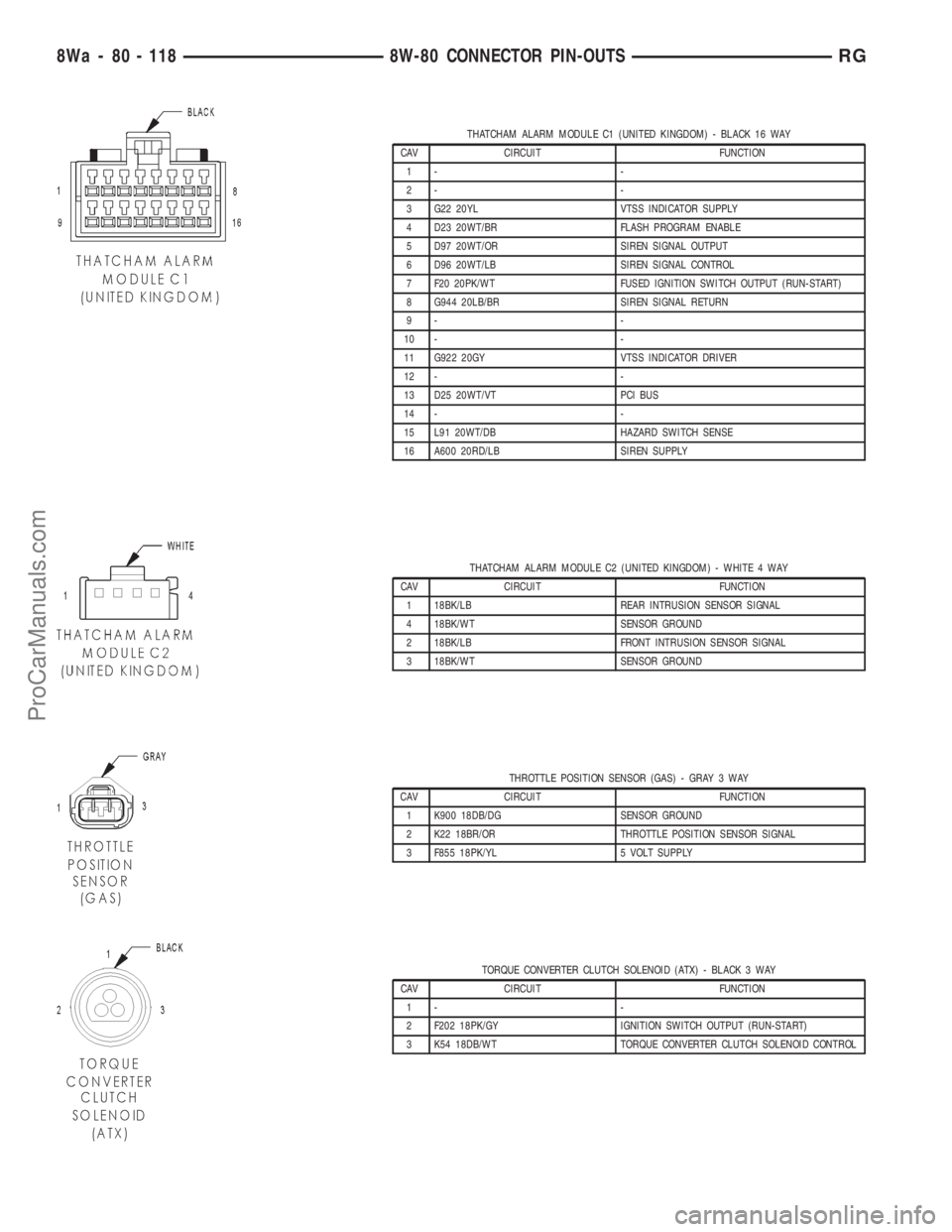
THATCHAM ALARM MODULE C1 (UNITED KINGDOM) - BLACK 16 WAY
CAV CIRCUIT FUNCTION
1- -
2- -
3 G22 20YL VTSS INDICATOR SUPPLY
4 D23 20WT/BR FLASH PROGRAM ENABLE
5 D97 20WT/OR SIREN SIGNAL OUTPUT
6 D96 20WT/LB SIREN SIGNAL CONTROL
7 F20 20PK/WT FUSED IGNITION SWITCH OUTPUT (RUN-START)
8 G944 20LB/BR SIREN SIGNAL RETURN
9- -
10 - -
11 G922 20GY VTSS INDICATOR DRIVER
12 - -
13 D25 20WT/VT PCI BUS
14 - -
15 L91 20WT/DB HAZARD SWITCH SENSE
16 A600 20RD/LB SIREN SUPPLY
THATCHAM ALARM MODULE C2 (UNITED KINGDOM) - WHITE 4 WAY
CAV CIRCUIT FUNCTION
1 18BK/LB REAR INTRUSION SENSOR SIGNAL
4 18BK/WT SENSOR GROUND
2 18BK/LB FRONT INTRUSION SENSOR SIGNAL
3 18BK/WT SENSOR GROUND
THROTTLE POSITION SENSOR (GAS) - GRAY 3 WAY
CAV CIRCUIT FUNCTION
1 K900 18DB/DG SENSOR GROUND
2 K22 18BR/OR THROTTLE POSITION SENSOR SIGNAL
3 F855 18PK/YL 5 VOLT SUPPLY
TORQUE CONVERTER CLUTCH SOLENOID (ATX) - BLACK 3 WAY
CAV CIRCUIT FUNCTION
1- -
2 F202 18PK/GY IGNITION SWITCH OUTPUT (RUN-START)
3 K54 18DB/WT TORQUE CONVERTER CLUTCH SOLENOID CONTROL
8Wa - 80 - 118 8W-80 CONNECTOR PIN-OUTSRG
ProCarManuals.com
Page 1101 of 2321
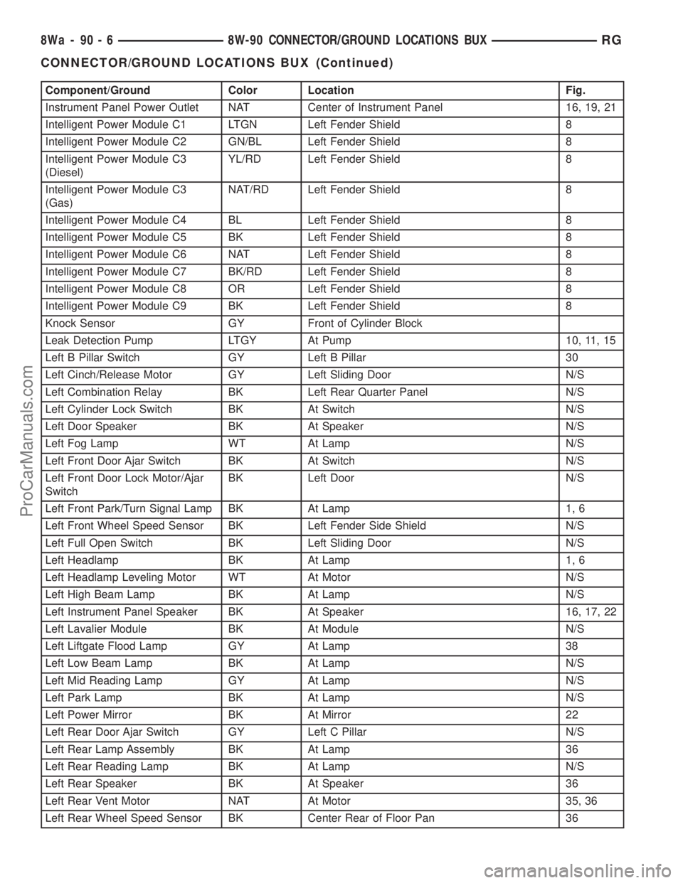
Component/Ground Color Location Fig.
Instrument Panel Power Outlet NAT Center of Instrument Panel 16, 19, 21
Intelligent Power Module C1 LTGN Left Fender Shield 8
Intelligent Power Module C2 GN/BL Left Fender Shield 8
Intelligent Power Module C3
(Diesel)YL/RD Left Fender Shield 8
Intelligent Power Module C3
(Gas)NAT/RD Left Fender Shield 8
Intelligent Power Module C4 BL Left Fender Shield 8
Intelligent Power Module C5 BK Left Fender Shield 8
Intelligent Power Module C6 NAT Left Fender Shield 8
Intelligent Power Module C7 BK/RD Left Fender Shield 8
Intelligent Power Module C8 OR Left Fender Shield 8
Intelligent Power Module C9 BK Left Fender Shield 8
Knock Sensor GY Front of Cylinder Block
Leak Detection Pump LTGY At Pump 10, 11, 15
Left B Pillar Switch GY Left B Pillar 30
Left Cinch/Release Motor GY Left Sliding Door N/S
Left Combination Relay BK Left Rear Quarter Panel N/S
Left Cylinder Lock Switch BK At Switch N/S
Left Door Speaker BK At Speaker N/S
Left Fog Lamp WT At Lamp N/S
Left Front Door Ajar Switch BK At Switch N/S
Left Front Door Lock Motor/Ajar
SwitchBK Left Door N/S
Left Front Park/Turn Signal Lamp BK At Lamp 1, 6
Left Front Wheel Speed Sensor BK Left Fender Side Shield N/S
Left Full Open Switch BK Left Sliding Door N/S
Left Headlamp BK At Lamp 1, 6
Left Headlamp Leveling Motor WT At Motor N/S
Left High Beam Lamp BK At Lamp N/S
Left Instrument Panel Speaker BK At Speaker 16, 17, 22
Left Lavalier Module BK At Module N/S
Left Liftgate Flood Lamp GY At Lamp 38
Left Low Beam Lamp BK At Lamp N/S
Left Mid Reading Lamp GY At Lamp N/S
Left Park Lamp BK At Lamp N/S
Left Power Mirror BK At Mirror 22
Left Rear Door Ajar Switch GY Left C Pillar N/S
Left Rear Lamp Assembly BK At Lamp 36
Left Rear Reading Lamp BK At Lamp N/S
Left Rear Speaker BK At Speaker 36
Left Rear Vent Motor NAT At Motor 35, 36
Left Rear Wheel Speed Sensor BK Center Rear of Floor Pan 36
8Wa - 90 - 6 8W-90 CONNECTOR/GROUND LOCATIONS BUXRG
CONNECTOR/GROUND LOCATIONS BUX (Continued)
ProCarManuals.com
Page 1102 of 2321
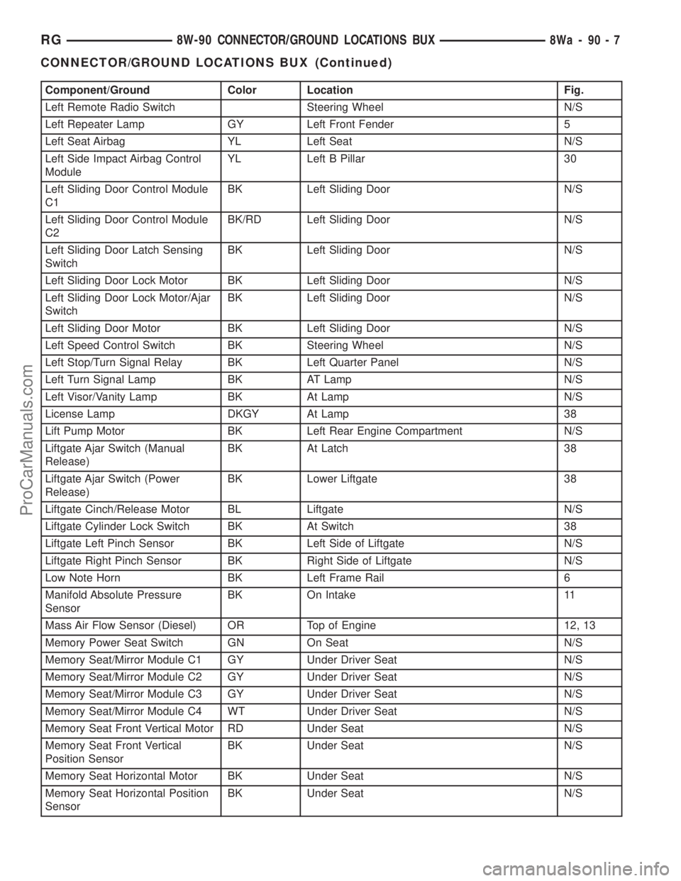
Component/Ground Color Location Fig.
Left Remote Radio Switch Steering Wheel N/S
Left Repeater Lamp GY Left Front Fender 5
Left Seat Airbag YL Left Seat N/S
Left Side Impact Airbag Control
ModuleYL Left B Pillar 30
Left Sliding Door Control Module
C1BK Left Sliding Door N/S
Left Sliding Door Control Module
C2BK/RD Left Sliding Door N/S
Left Sliding Door Latch Sensing
SwitchBK Left Sliding Door N/S
Left Sliding Door Lock Motor BK Left Sliding Door N/S
Left Sliding Door Lock Motor/Ajar
SwitchBK Left Sliding Door N/S
Left Sliding Door Motor BK Left Sliding Door N/S
Left Speed Control Switch BK Steering Wheel N/S
Left Stop/Turn Signal Relay BK Left Quarter Panel N/S
Left Turn Signal Lamp BK AT Lamp N/S
Left Visor/Vanity Lamp BK At Lamp N/S
License Lamp DKGY At Lamp 38
Lift Pump Motor BK Left Rear Engine Compartment N/S
Liftgate Ajar Switch (Manual
Release)BK At Latch 38
Liftgate Ajar Switch (Power
Release)BK Lower Liftgate 38
Liftgate Cinch/Release Motor BL Liftgate N/S
Liftgate Cylinder Lock Switch BK At Switch 38
Liftgate Left Pinch Sensor BK Left Side of Liftgate N/S
Liftgate Right Pinch Sensor BK Right Side of Liftgate N/S
Low Note Horn BK Left Frame Rail 6
Manifold Absolute Pressure
SensorBK On Intake 11
Mass Air Flow Sensor (Diesel) OR Top of Engine 12, 13
Memory Power Seat Switch GN On Seat N/S
Memory Seat/Mirror Module C1 GY Under Driver Seat N/S
Memory Seat/Mirror Module C2 GY Under Driver Seat N/S
Memory Seat/Mirror Module C3 GY Under Driver Seat N/S
Memory Seat/Mirror Module C4 WT Under Driver Seat N/S
Memory Seat Front Vertical Motor RD Under Seat N/S
Memory Seat Front Vertical
Position SensorBK Under Seat N/S
Memory Seat Horizontal Motor BK Under Seat N/S
Memory Seat Horizontal Position
SensorBK Under Seat N/S
RG8W-90 CONNECTOR/GROUND LOCATIONS BUX8Wa-90-7
CONNECTOR/GROUND LOCATIONS BUX (Continued)
ProCarManuals.com
Page 1105 of 2321
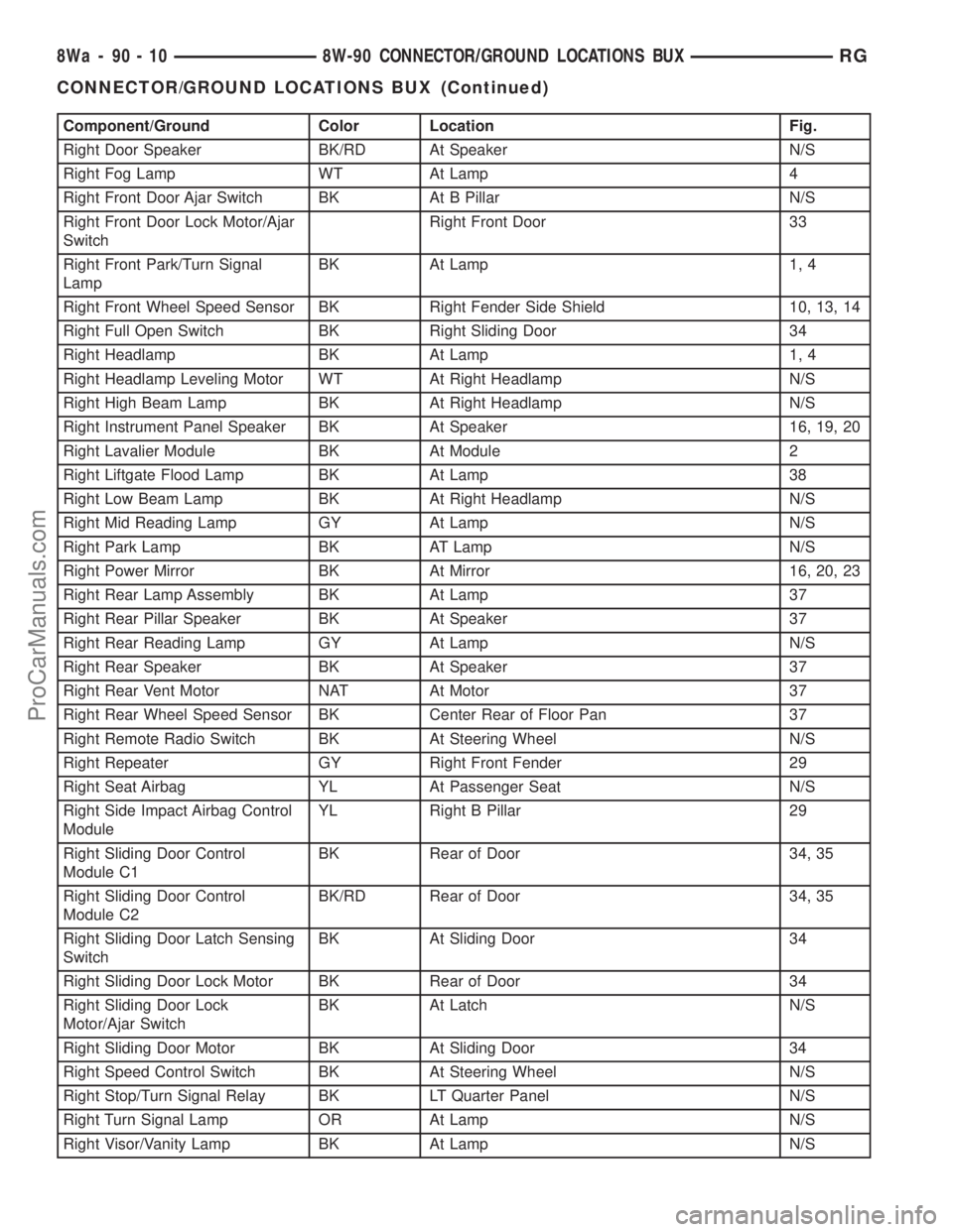
Component/Ground Color Location Fig.
Right Door Speaker BK/RD At Speaker N/S
Right Fog Lamp WT At Lamp 4
Right Front Door Ajar Switch BK At B Pillar N/S
Right Front Door Lock Motor/Ajar
SwitchRight Front Door 33
Right Front Park/Turn Signal
LampBK At Lamp 1, 4
Right Front Wheel Speed Sensor BK Right Fender Side Shield 10, 13, 14
Right Full Open Switch BK Right Sliding Door 34
Right Headlamp BK At Lamp 1, 4
Right Headlamp Leveling Motor WT At Right Headlamp N/S
Right High Beam Lamp BK At Right Headlamp N/S
Right Instrument Panel Speaker BK At Speaker 16, 19, 20
Right Lavalier Module BK At Module 2
Right Liftgate Flood Lamp BK At Lamp 38
Right Low Beam Lamp BK At Right Headlamp N/S
Right Mid Reading Lamp GY At Lamp N/S
Right Park Lamp BK AT Lamp N/S
Right Power Mirror BK At Mirror 16, 20, 23
Right Rear Lamp Assembly BK At Lamp 37
Right Rear Pillar Speaker BK At Speaker 37
Right Rear Reading Lamp GY At Lamp N/S
Right Rear Speaker BK At Speaker 37
Right Rear Vent Motor NAT At Motor 37
Right Rear Wheel Speed Sensor BK Center Rear of Floor Pan 37
Right Remote Radio Switch BK At Steering Wheel N/S
Right Repeater GY Right Front Fender 29
Right Seat Airbag YL At Passenger Seat N/S
Right Side Impact Airbag Control
ModuleYL Right B Pillar 29
Right Sliding Door Control
Module C1BK Rear of Door 34, 35
Right Sliding Door Control
Module C2BK/RD Rear of Door 34, 35
Right Sliding Door Latch Sensing
SwitchBK At Sliding Door 34
Right Sliding Door Lock Motor BK Rear of Door 34
Right Sliding Door Lock
Motor/Ajar SwitchBK At Latch N/S
Right Sliding Door Motor BK At Sliding Door 34
Right Speed Control Switch BK At Steering Wheel N/S
Right Stop/Turn Signal Relay BK LT Quarter Panel N/S
Right Turn Signal Lamp OR At Lamp N/S
Right Visor/Vanity Lamp BK At Lamp N/S
8Wa - 90 - 10 8W-90 CONNECTOR/GROUND LOCATIONS BUXRG
CONNECTOR/GROUND LOCATIONS BUX (Continued)
ProCarManuals.com
Page 1390 of 2321
The turbocharger is lubricated by engine oil that is
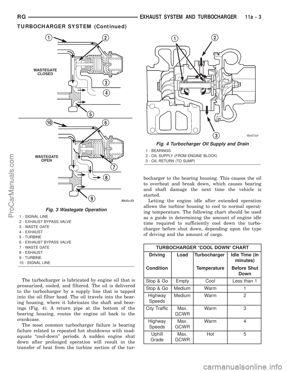
pressurized, cooled, and filtered. The oil is delivered
to the turbocharger by a supply line that is tapped
into the oil filter head. The oil travels into the bear-
ing housing, where it lubricates the shaft and bear-
ings (Fig. 4). A return pipe at the bottom of the
bearing housing, routes the engine oil back to the
crankcase.
The most common turbocharger failure is bearing
failure related to repeated hot shutdowns with inad-
equate ªcool-downº periods. A sudden engine shut
down after prolonged operation will result in the
transfer of heat from the turbine section of the tur-bocharger to the bearing housing. This causes the oil
to overheat and break down, which causes bearing
and shaft damage the next time the vehicle is
started.
Letting the engine idle after extended operation
allows the turbine housing to cool to normal operat-
ing temperature. The following chart should be used
as a guide in determining the amount of engine idle
time required to sufficiently cool down the turbo-
charger before shut down, depending upon the type
of driving and the amount of cargo.
TURBOCHARGER(COOL DOWN(CHART
Driving Load Turbocharger Idle Time (in
minutes)
Condition Temperature Before Shut
Down
Stop & Go Empty Cool Less than 1
Stop & Go Medium Warm 1
Highway
SpeedsMedium Warm 2
City Traffic Max.
GCWRWarm 3
Highway
SpeedsMax.
GCWRWarm 4
Uphill
GradeMax.
GCWRHot 5
Fig. 3 Wastegate Operation
1 - SIGNAL LINE
2 - EXHAUST BYPASS VALVE
3 - WASTE GATE
4 - EXHAUST
5 - TURBINE
6 - EXHAUST BYPASS VALVE
7 - WASTE GATE
8 - EXHAUST
9 - TURBINE
10 - SIGNAL LINE
Fig. 4 Turbocharger Oil Supply and Drain
1 - BEARINGS
2 - OIL SUPPLY (FROM ENGINE BLOCK)
3 - OIL RETURN (TO SUMP)
RGEXHAUST SYSTEM AND TURBOCHARGER11a-3
TURBOCHARGER SYSTEM (Continued)
ProCarManuals.com
Page 1395 of 2321
FRONT FASCIA
REMOVAL
(1) Release hood latch and open hood.
(2) Remove the headlamp assemblies. Refer to
group 8 exterior lighting.
(3) Remove two bolts attaching the upper grill sup-
port to the headlamp mounting panel at each side of
the grille.
(4) Hoist vehicle and support with safety stands.
(5)
Remove front wheels. Refer to Group 22, Wheels
and Tires, for proper procedures and sequence.
(6) Remove front wheelhouse splash shields fasten-
ers as necessary to gain access to bolts holding front
fascia to fender. Refer to Group 23, Body, for proper
procedures.
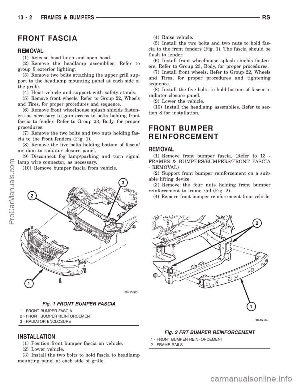
(7) Remove the two bolts and two nuts holding fas-
cia to the front fenders (Fig. 1).
(8) Remove the five bolts holding bottom of fascia/
air dam to radiator closure panel.
(9) Disconnect fog lamp/parking and turn signal
lamp wire connector, as necessary.
(10) Remove bumper fascia from vehicle.
INSTALLATION
(1) Position front bumper fascia on vehicle.
(2) Lower vehicle.
(3) Install the two bolts to hold fascia to headlamp
mounting panel at each side of grille.(4) Raise vehicle.
(5) Install the two bolts and two nuts to hold fas-
cia to the front fenders (Fig. 1). The fascia should be
flush to fender.
(6) Install front wheelhouse splash shields fasten-
ers. Refer to Group 23, Body, for proper procedures.
(7) Install front wheels. Refer to Group 22, Wheels
and Tires, for proper procedures and tightening
sequence.
(8) Install the five bolts to hold bottom of fascia to
radiator closure panel.
(9) Lower the vehicle.
(10) Install the headlamp assemblies. Refer to sec-
tion 8 for installation.
FRONT BUMPER
REINFORCEMENT
REMOVAL
(1) Remove front bumper fascia. (Refer to 13 -
FRAMES & BUMPERS/BUMPERS/FRONT FASCIA
- REMOVAL)
(2) Support front bumper reinforcement on a suit-
able lifting device.
(3) Remove the four nuts holding front bumper
reinforcement to frame rail (Fig. 2).
(4) Remove front bumper reinforcement from vehicle.
Fig. 1 FRONT BUMPER FASCIA
1 - FRONT BUMPER FASCIA
2 - FRONT BUMPER REINFORCEMENT
3 - RADIATOR ENCLOSURE
Fig. 2 FRT BUMPER REINFORCEMENT
1 - FRONT BUMPER REINFORCEMENT
2 - FRAME RAILS
13 - 2 FRAMES & BUMPERSRS
ProCarManuals.com
Page 1411 of 2321
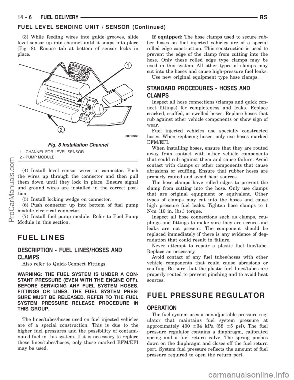
(3) While feeding wires into guide grooves, slide
level sensor up into channel until it snaps into place
(Fig. 8). Ensure tab at bottom of sensor locks in
place.
(4) Install level sensor wires in connector. Push
the wires up through the connector and then pull
them down until they lock in place. Ensure signal
and ground wires are installed in the correct posi-
tion.
(5) Install locking wedge on connector.
(6) Push connector up into bottom of fuel pump
module electrical connector.
(7) Install fuel pump module. Refer to Fuel Pump
Module in this section.
FUEL LINES
DESCRIPTION - FUEL LINES/HOSES AND
CLAMPS
Also refer to Quick-Connect Fittings.
WARNING: THE FUEL SYSTEM IS UNDER A CON-
STANT PRESSURE (EVEN WITH THE ENGINE OFF).
BEFORE SERVICING ANY FUEL SYSTEM HOSES,
FITTINGS OR LINES, THE FUEL SYSTEM PRES-
SURE MUST BE RELEASED. REFER TO THE FUEL
SYSTEM PRESSURE RELEASE PROCEDURE IN
THIS GROUP.
The lines/tubes/hoses used on fuel injected vehicles
are of a special construction. This is due to the
higher fuel pressures and the possibility of contami-
nated fuel in this system. If it is necessary to replace
these lines/tubes/hoses, only those marked EFM/EFI
may be used.If equipped:The hose clamps used to secure rub-
ber hoses on fuel injected vehicles are of a special
rolled edge construction. This construction is used to
prevent the edge of the clamp from cutting into the
hose. Only these rolled edge type clamps may be
used in this system. All other types of clamps may
cut into the hoses and cause high-pressure fuel leaks.
Use new original equipment type hose clamps.
STANDARD PROCEDURES - HOSES AND
CLAMPS
Inspect all hose connections (clamps and quick con-
nect fittings) for completeness and leaks. Replace
cracked, scuffed, or swelled hoses. Replace hoses that
rub against other vehicle components or show sign of
wear.
Fuel injected vehicles use specially constructed
hoses. When replacing hoses, only use hoses marked
EFM/EFI.
When installing hoses, ensure that they are routed
away from contact with other vehicle components
that could rub against them and cause failure. Avoid
contact with clamps or other components that cause
abrasions or scuffing. Ensure that rubber hoses are
properly routed and avoid heat sources.
The hose clamps have rolled edges to prevent the
clamp from cutting into the hose. Only use clamps
that are original equipment or equivalent. Other
types of clamps may cut into the hoses and cause
high pressure fuel leaks. Tighten hose clamps to 1
N´m (10 in. lbs.) torque.
Inspect all hose connections such as clamps, cou-
plings and fittings to make sure they are secure and
leaks are not present. The component should be
replaced immediately if there is any evidence of deg-
radation that could result in failure.
Never attempt to repair a plastic fuel line/tube.
Replace as necessary.
Avoid contact of any fuel tubes/hoses with other
vehicle components that could cause abrasions or
scuffing. Be sure that the plastic fuel lines/tubes are
properly routed to prevent pinching and to avoid heat
sources.
FUEL PRESSURE REGULATOR
OPERATION
The fuel system uses a nonadjustable pressure reg-
ulator that maintains fuel system pressure at
approximately 400634 kPa (5865 psi). The fuel
pressure regulator contains a diaphragm, calibrated
spring and a fuel return valve. The spring pushes
down on the diaphragm and closes off the fuel return
port. System fuel pressure reflects the amount of fuel
pressure required to open the return port.
Fig. 8 Installation Channel
1 - CHANNEL FOR LEVEL SENSOR
2 - PUMP MODULE
14 - 6 FUEL DELIVERYRS
FUEL LEVEL SENDING UNIT / SENSOR (Continued)
ProCarManuals.com
Page 1422 of 2321
the PCM must calculate a different injector pulse
width and ignition timing for idle than it does for
Wide Open Throttle (WOT). There are several differ-
ent modes of operation that determine how the PCM
responds to the various input signals.
There are two different areas of operation, OPEN
LOOP and CLOSED LOOP.
During OPEN LOOP modes the PCM receives
input signals and responds according to preset PCM
programming. Inputs from the upstream and down-
stream heated oxygen sensors are not monitored dur-
ing OPEN LOOP modes, except for heated oxygen
sensor diagnostics (they are checked for shorted con-
ditions at all times).
During CLOSED LOOP modes the PCM monitors
the inputs from the upstream and downstream
heated oxygen sensors. The upstream heated oxygen
sensor input tells the PCM if the calculated injector
pulse width resulted in the ideal air-fuel ratio of 14.7
to one. By monitoring the exhaust oxygen content
through the upstream heated oxygen sensor, the
PCM can fine tune injector pulse width. Fine tuning
injector pulse width allows the PCM to achieve opti-
mum fuel economy combined with low emissions.
For the PCM to enter CLOSED LOOP operation,
the following must occur:
(1) Engine coolant temperature must be over 35ÉF.
²If the coolant is over 35É the PCM will wait 44
seconds.
²If the coolant is over 50ÉF the PCM will wait 38
seconds.
²If the coolant is over 167ÉF the PCM will wait
11 seconds.
(2) For other temperatures the PCM will interpo-
late the correct waiting time.
(3) O2 sensor must read either greater than 0.745
volts or less than 0.1 volt.
(4) The multi-port fuel injection systems has the
following modes of operation:
²Ignition switch ON (Zero RPM)
²Engine start-up
²Engine warm-up
²Cruise
²Idle
²Acceleration
²Deceleration
²Wide Open Throttle
²Ignition switch OFF
(5) The engine start-up (crank), engine warm-up,
deceleration with fuel shutoff and wide open throttle
modes are OPEN LOOP modes. Under most operat-
ing conditions, the acceleration, deceleration (with
A/C on), idle and cruise modes,with the engine at
operating temperatureare CLOSED LOOP modes.IGNITION SWITCH ON (ZERO RPM) MODE
When the ignition switch activates the fuel injec-
tion system, the following actions occur:
²The PCM monitors the engine coolant tempera-
ture sensor and throttle position sensor input. The
PCM determines basic fuel injector pulse width from
this input.
²The PCM determines atmospheric air pressure
from the MAP sensor input to modify injector pulse
width.
When the key is in the ON position and the engine
is not running (zero rpm), the Auto Shutdown (ASD)
and fuel pump relays de-energize after approximately
1 second. Therefore, battery voltage is not supplied to
the fuel pump, ignition coil, fuel injectors and heated
oxygen sensors.
ENGINE START-UP MODE
This is an OPEN LOOP mode. If the vehicle is in
park or neutral (automatic transaxles) or the clutch
pedal is depressed (manual transaxles) the ignition
switch energizes the starter relay. The following
actions occur when the starter motor is engaged.
²If the PCM receives the camshaft position sensor
and crankshaft position sensor signals, it energizes
the Auto Shutdown (ASD) relay and fuel pump relay.
If the PCM does not receive both signals within
approximately one second, it will not energize the
ASD relay and fuel pump relay. The ASD and fuel
pump relays supply battery voltage to the fuel pump,
fuel injectors, ignition coil and heated oxygen sen-
sors.
²The PCM energizes the injectors (on the 69É
degree falling edge) for a calculated pulse width until
it determines crankshaft position from the camshaft
position sensor and crankshaft position sensor sig-
nals. The PCM determines crankshaft position within
1 engine revolution.
²After determining crankshaft position, the PCM
begins energizing the injectors in sequence. It adjusts
injector pulse width and controls injector synchroni-
zation by turning the individual ground paths to the
injectors On and Off.
²When the engine idles within664 RPM of its
target RPM, the PCM compares current MAP sensor
value with the atmospheric pressure value received
during the Ignition Switch On (zero RPM) mode.
Once the ASD and fuel pump relays have been
energized, the PCM determines injector pulse width
based on the following:
²Battery voltage
²Engine coolant temperature
²Engine RPM
²Inlet/Intake air temperature (IAT)
²MAP
²Throttle position
RSFUEL INJECTION14-17
FUEL INJECTION (Continued)
ProCarManuals.com