2001 DODGE RAM NV5600
[x] Cancel search: NV5600Page 19 of 2889
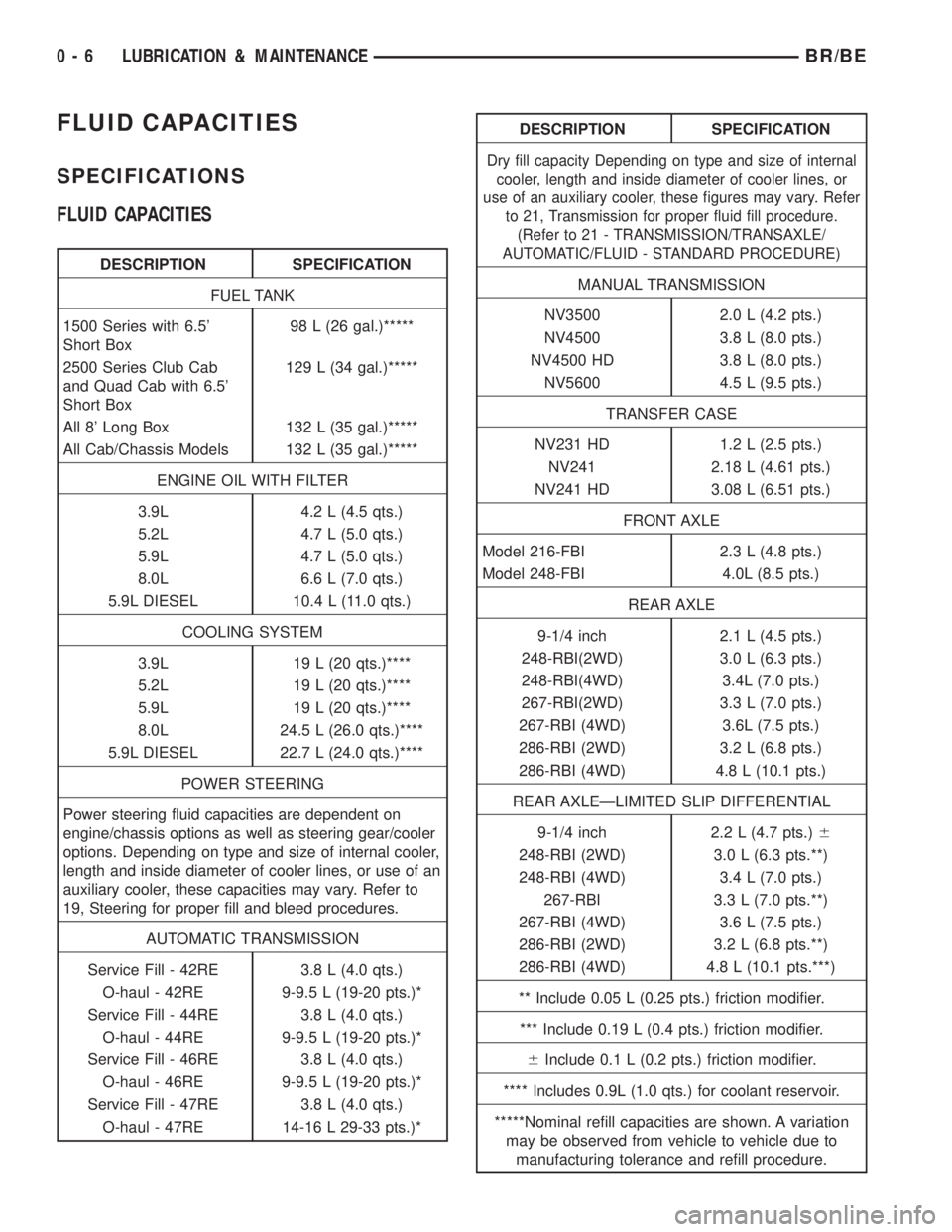
FLUID CAPACITIES
SPECIFICATIONS
FLUID CAPACITIES
DESCRIPTION SPECIFICATION
FUEL TANK
1500 Series with 6.5'
Short Box98 L (26 gal.)*****
2500 Series Club Cab
and Quad Cab with 6.5'
Short Box129 L (34 gal.)*****
All 8' Long Box 132 L (35 gal.)*****
All Cab/Chassis Models 132 L (35 gal.)*****
ENGINE OIL WITH FILTER
3.9L 4.2 L (4.5 qts.)
5.2L 4.7 L (5.0 qts.)
5.9L 4.7 L (5.0 qts.)
8.0L 6.6 L (7.0 qts.)
5.9L DIESEL 10.4 L (11.0 qts.)
COOLING SYSTEM
3.9L 19 L (20 qts.)****
5.2L 19 L (20 qts.)****
5.9L 19 L (20 qts.)****
8.0L 24.5 L (26.0 qts.)****
5.9L DIESEL 22.7 L (24.0 qts.)****
POWER STEERING
Power steering fluid capacities are dependent on
engine/chassis options as well as steering gear/cooler
options. Depending on type and size of internal cooler,
length and inside diameter of cooler lines, or use of an
auxiliary cooler, these capacities may vary. Refer to
19, Steering for proper fill and bleed procedures.
AUTOMATIC TRANSMISSION
Service Fill - 42RE 3.8 L (4.0 qts.)
O-haul - 42RE 9-9.5 L (19-20 pts.)*
Service Fill - 44RE 3.8 L (4.0 qts.)
O-haul - 44RE 9-9.5 L (19-20 pts.)*
Service Fill - 46RE 3.8 L (4.0 qts.)
O-haul - 46RE 9-9.5 L (19-20 pts.)*
Service Fill - 47RE 3.8 L (4.0 qts.)
O-haul - 47RE 14-16 L 29-33 pts.)*
DESCRIPTION SPECIFICATION
Dry fill capacity Depending on type and size of internal
cooler, length and inside diameter of cooler lines, or
use of an auxiliary cooler, these figures may vary. Refer
to 21, Transmission for proper fluid fill procedure.
(Refer to 21 - TRANSMISSION/TRANSAXLE/
AUTOMATIC/FLUID - STANDARD PROCEDURE)
MANUAL TRANSMISSION
NV3500 2.0 L (4.2 pts.)
NV4500 3.8 L (8.0 pts.)
NV4500 HD 3.8 L (8.0 pts.)
NV5600 4.5 L (9.5 pts.)
TRANSFER CASE
NV231 HD 1.2 L (2.5 pts.)
NV241 2.18 L (4.61 pts.)
NV241 HD 3.08 L (6.51 pts.)
FRONT AXLE
Model 216-FBI 2.3 L (4.8 pts.)
Model 248-FBI 4.0L (8.5 pts.)
REAR AXLE
9-1/4 inch 2.1 L (4.5 pts.)
248-RBI(2WD) 3.0 L (6.3 pts.)
248-RBI(4WD) 3.4L (7.0 pts.)
267-RBI(2WD) 3.3 L (7.0 pts.)
267-RBI (4WD) 3.6L (7.5 pts.)
286-RBI (2WD) 3.2 L (6.8 pts.)
286-RBI (4WD) 4.8 L (10.1 pts.)
REAR AXLEÐLIMITED SLIP DIFFERENTIAL
9-1/4 inch 2.2 L (4.7 pts.)6
248-RBI (2WD) 3.0 L (6.3 pts.**)
248-RBI (4WD) 3.4 L (7.0 pts.)
267-RBI 3.3 L (7.0 pts.**)
267-RBI (4WD) 3.6 L (7.5 pts.)
286-RBI (2WD) 3.2 L (6.8 pts.**)
286-RBI (4WD) 4.8 L (10.1 pts.***)
** Include 0.05 L (0.25 pts.) friction modifier.
*** Include 0.19 L (0.4 pts.) friction modifier.
6Include 0.1 L (0.2 pts.) friction modifier.
**** Includes 0.9L (1.0 qts.) for coolant reservoir.
*****Nominal refill capacities are shown. A variation
may be observed from vehicle to vehicle due to
manufacturing tolerance and refill procedure.
0 - 6 LUBRICATION & MAINTENANCEBR/BE
Page 324 of 2889
CLUTCH HOUSING
DIAGNOSIS AND TESTING - CLUTCH HOUSING
Clutch housing alignment is important to proper
clutch operation. The housing maintains alignment
between the crankshaft and transmission input
shaft. Misalignment can cause clutch noise, hard
shifting, incomplete release and chatter. It can also
result in premature wear of the pilot bearing, cover
release fingers and clutch disc. In severe cases, mis-
alignment can also cause premature wear of the
transmission input shaft and front bearing.
Housing misalignment is generally caused by
incorrect seating on the engine or transmission, loose
housing bolts, missing alignment dowels, or housing
damage. Infrequently, misalignment may also be
caused by housing mounting surfaces that are not
completely parallel. Misalignment can be corrected
with shims.
CHECKING RUNOUT
Only the NV4500 clutch housing can be
checked using the following bore and face
runout procedures. The NV3500 and NV5600
clutch housings are an integral part of the
transmission and can only be checked off the
vehicle.
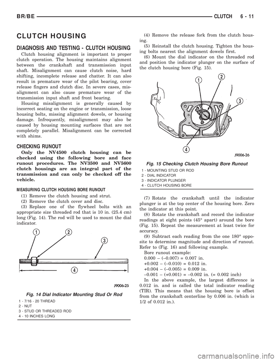
MEASURING CLUTCH HOUSING BORE RUNOUT
(1) Remove the clutch housing and strut.
(2) Remove the clutch cover and disc.
(3) Replace one of the flywheel bolts with an
appropriate size threaded rod that is 10 in. (25.4 cm)
long (Fig. 14). The rod will be used to mount the dial
indicator.(4) Remove the release fork from the clutch hous-
ing.
(5) Reinstall the clutch housing. Tighten the hous-
ing bolts nearest the alignment dowels first.
(6) Mount the dial indicator on the threaded rod
and position the indicator plunger on the surface of
the clutch housing bore (Fig. 15).
(7) Rotate the crankshaft until the indicator
plunger is at the top center of the housing bore. Zero
the indicator at this point.
(8) Rotate the crankshaft and record the indicator
readings at eight points (45É apart) around the bore
(Fig. 15). Repeat the measurement at least twice for
accuracy.
(9) Subtract each reading from the one 180É oppo-
site to determine magnitude and direction of runout.
Refer to (Fig. 16) and following example.
Bore runout example:
0.000 ± (±0.007) = 0.007 in.
+0.002 ± (±0.010) = 0.012 in.
+0.004 ± (±0.005) = 0.009 in.
±0.001 ± (+0.001) = ±0.002 in. (= 0.002 inch)
In the above example, the largest difference is
0.012 in. and is called the total indicator reading
(TIR). This means that the housing bore is offset
from the crankshaft centerline by 0.006 in. (which is
1/2 of 0.012 in.).
Fig. 14 Dial Indicator Mounting Stud Or Rod
1 - 7/16 - 20 THREAD
2 - NUT
3 - STUD OR THREADED ROD
4 - 10 INCHES LONG
Fig. 15 Checking Clutch Housing Bore Runout
1 - MOUNTING STUD OR ROD
2 - DIAL INDICATOR
3 - INDICATOR PLUNGER
4 - CLUTCH HOUSING BORE
BR/BECLUTCH 6 - 11
Page 1636 of 2889
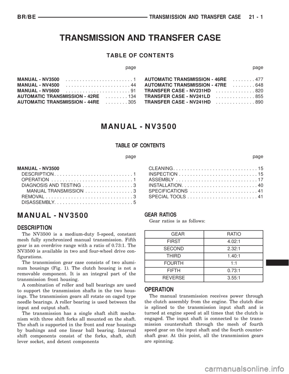
TRANSMISSION AND TRANSFER CASE
TABLE OF CONTENTS
page page
MANUAL - NV3500........................1
MANUAL - NV4500.......................44
MANUAL - NV5600.......................91
AUTOMATIC TRANSMISSION - 42RE........134
AUTOMATIC TRANSMISSION - 44RE........305AUTOMATIC TRANSMISSION - 46RE........477
AUTOMATIC TRANSMISSION - 47RE........648
TRANSFER CASE - NV231HD..............820
TRANSFER CASE - NV241LD..............855
TRANSFER CASE - NV241HD..............890
MANUAL - NV3500
TABLE OF CONTENTS
page page
MANUAL - NV3500
DESCRIPTION............................1
OPERATION.............................1
DIAGNOSIS AND TESTING..................3
MANUAL TRANSMISSION.................3
REMOVAL...............................3
DISASSEMBLY............................5CLEANING..............................15
INSPECTION............................15
ASSEMBLY.............................17
INSTALLATION...........................40
SPECIFICATIONS........................41
SPECIAL TOOLS.........................41
MANUAL - NV3500
DESCRIPTION
The NV3500 is a medium-duty 5-speed, constant
mesh fully synchronized manual transmission. Fifth
gear is an overdrive range with a ratio of 0.73:1. The
NV3500 is available in two and four-wheel drive con-
figurations.
The transmission gear case consists of two alumi-
num housings (Fig. 1). The clutch housing is not a
removable component. It is an integral part of the
transmission front housing.
A combination of roller and ball bearings are used
to support the transmission shafts in the two hous-
ings. The transmission gears all rotate on caged type
needle bearings. A roller bearing is used between the
input and output shaft.
The transmission has a single shaft shift mecha-
nism with three shift forks all mounted on the shaft.
The shaft is supported in the front and rear housings
by bushings and one linear ball bearing. Internal
shift components consist of the forks, shaft, shift
lever socket, and detent components
GEAR RATIOS
Gear ratios is as follows:
GEAR RATIO
FIRST 4.02:1
SECOND 2.32:1
THIRD 1.40:1
FOURTH 1:1
FIFTH 0.73:1
REVERSE 3.55:1
OPERATION
The manual transmission receives power through
the clutch assembly from the engine. The clutch disc
is splined to the transmission input shaft and is
turned at engine speed at all times that the clutch is
engaged. The input shaft is connected to the trans-
mission countershaft through the mesh of fourth
speed gear on the input shaft and the fourth counter-
shaft gear. At this point, all the transmission gears
are spinning.
BR/BETRANSMISSION AND TRANSFER CASE 21 - 1
Page 1726 of 2889
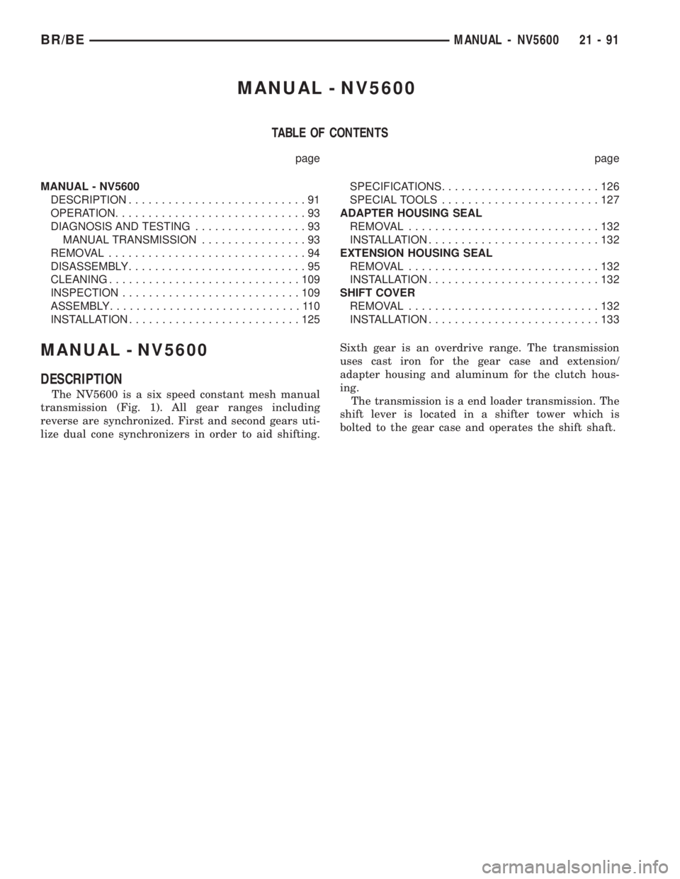
MANUAL - NV5600
TABLE OF CONTENTS
page page
MANUAL - NV5600
DESCRIPTION...........................91
OPERATION.............................93
DIAGNOSIS AND TESTING.................93
MANUAL TRANSMISSION................93
REMOVAL..............................94
DISASSEMBLY...........................95
CLEANING.............................109
INSPECTION...........................109
ASSEMBLY.............................110
INSTALLATION..........................125SPECIFICATIONS........................126
SPECIAL TOOLS........................127
ADAPTER HOUSING SEAL
REMOVAL.............................132
INSTALLATION..........................132
EXTENSION HOUSING SEAL
REMOVAL.............................132
INSTALLATION..........................132
SHIFT COVER
REMOVAL.............................132
INSTALLATION..........................133
MANUAL - NV5600
DESCRIPTION
The NV5600 is a six speed constant mesh manual
transmission (Fig. 1). All gear ranges including
reverse are synchronized. First and second gears uti-
lize dual cone synchronizers in order to aid shifting.Sixth gear is an overdrive range. The transmission
uses cast iron for the gear case and extension/
adapter housing and aluminum for the clutch hous-
ing.
The transmission is a end loader transmission. The
shift lever is located in a shifter tower which is
bolted to the gear case and operates the shift shaft.
BR/BEMANUAL - NV5600 21 - 91
Page 1727 of 2889
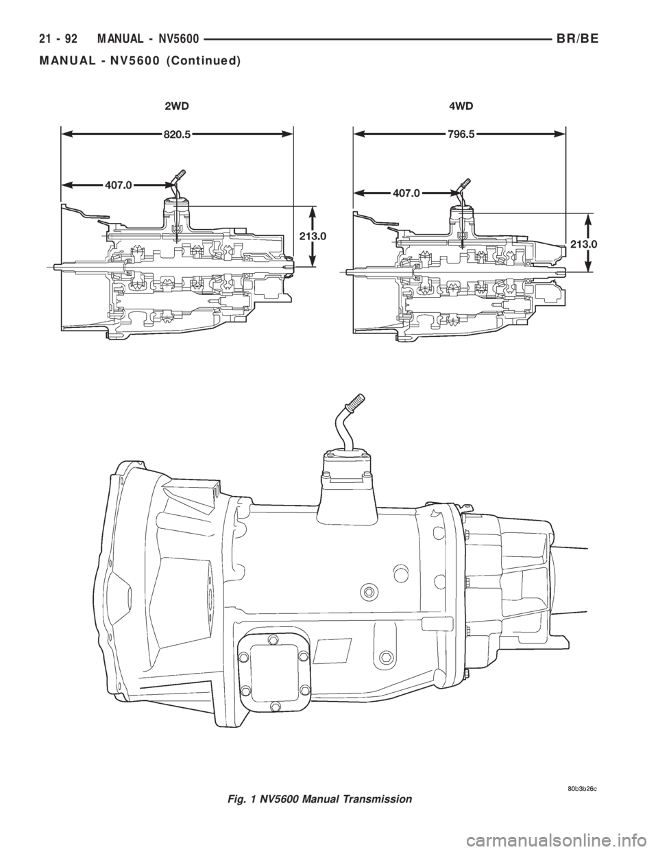
Fig. 1 NV5600 Manual Transmission
21 - 92 MANUAL - NV5600BR/BE
MANUAL - NV5600 (Continued)
Page 1728 of 2889
SHIFT PATTERN
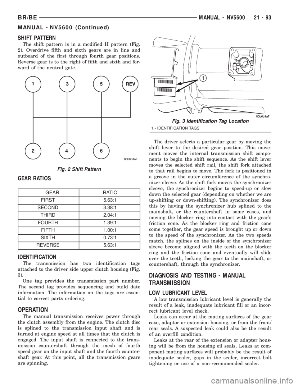
The shift pattern is in a modified H pattern (Fig.
2). Overdrive fifth and sixth gears are in line and
outboard of the first through fourth gear positions.
Reverse gear is to the right of fifth and sixth and for-
ward of the neutral gate.
GEAR RATIOS
GEAR RATIO
FIRST 5.63:1
SECOND 3.38:1
THIRD 2.04:1
FOURTH 1.39:1
FIFTH 1.00:1
SIXTH 0.73:1
REVERSE 5.63:1
IDENTIFICATION
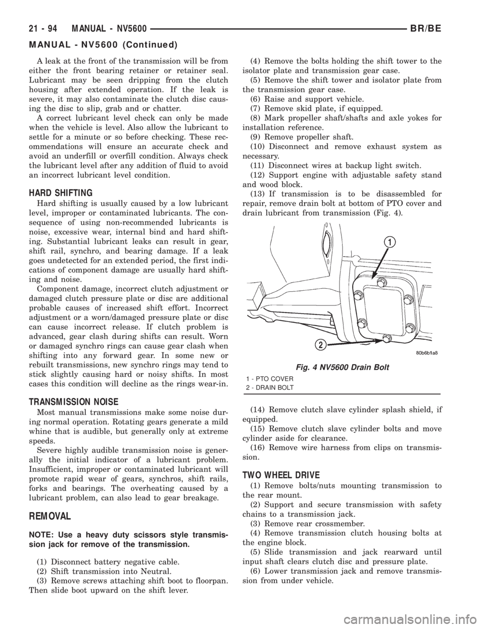
The transmission has two identification tags
attached to the driver side upper clutch housing (Fig.
3).
One tag provides the transmission part number.
The second tag provides sequencing and build date
information. The information on the tags are essen-
tial to correct parts ordering.
OPERATION
The manual transmission receives power through
the clutch assembly from the engine. The clutch disc
is splined to the transmission input shaft and is
turned at engine speed at all times that the clutch is
engaged. The input shaft is connected to the trans-
mission countershaft through the mesh of fourth
speed gear on the input shaft and the fourth counter-
shaft gear. At this point, all the transmission gears
are spinning.The driver selects a particular gear by moving the
shift lever to the desired gear position. This move-
ment moves the internal transmission shift compo-
nents to begin the shift sequence. As the shift lever
moves the selected shift rail, the shift fork attached
to that rail begins to move. The fork is positioned in
a groove in the outer circumference of the synchro-
nizer sleeve. As the shift fork moves the synchronizer
sleeve, the synchronizer begins to speed-up or slow
down the selected gear (depending on whether we are
up-shifting or down-shifting). The synchronizer does
this by having the synchronizer hub splined to the
mainshaft, or the countershaft in some cases, and
moving the blocker ring into contact with the gear's
friction cone. As the blocker ring and friction cone
come together, the gear speed is brought up or down
to the speed of the synchronizer. As the two speeds
match, the splines on the inside of the synchronizer
sleeve become aligned with the teeth on the blocker
ring and the friction cone and eventually will slide
over the teeth, locking the gear to the mainshaft, or
countershaft, through the synchronizer.
DIAGNOSIS AND TESTING - MANUAL
TRANSMISSION
LOW LUBRICANT LEVEL
A low transmission lubricant level is generally the
result of a leak, inadequate lubricant fill or an incor-
rect lubricant level check.
Leaks can occur at the mating surfaces of the gear
case, adaptor or extension housing, or from the front/
rear seals. A suspected leak could also be the result
of an overfill condition.
Leaks at the rear of the extension or adapter hous-
ing will be from the housing oil seals. Leaks at com-
ponent mating surfaces will probably be the result of
inadequate sealer, gaps in the sealer, incorrect bolt
tightening or use of a non-recommended sealer.
Fig. 2 Shift Pattern
Fig. 3 Identification Tag Location
1 - IDENTIFICATION TAGS
BR/BEMANUAL - NV5600 21 - 93
MANUAL - NV5600 (Continued)
Page 1729 of 2889
A leak at the front of the transmission will be from
either the front bearing retainer or retainer seal.
Lubricant may be seen dripping from the clutch
housing after extended operation. If the leak is
severe, it may also contaminate the clutch disc caus-
ing the disc to slip, grab and or chatter.
A correct lubricant level check can only be made
when the vehicle is level. Also allow the lubricant to
settle for a minute or so before checking. These rec-
ommendations will ensure an accurate check and
avoid an underfill or overfill condition. Always check
the lubricant level after any addition of fluid to avoid
an incorrect lubricant level condition.
HARD SHIFTING
Hard shifting is usually caused by a low lubricant
level, improper or contaminated lubricants. The con-
sequence of using non-recommended lubricants is
noise, excessive wear, internal bind and hard shift-
ing. Substantial lubricant leaks can result in gear,
shift rail, synchro, and bearing damage. If a leak
goes undetected for an extended period, the first indi-
cations of component damage are usually hard shift-
ing and noise.
Component damage, incorrect clutch adjustment or
damaged clutch pressure plate or disc are additional
probable causes of increased shift effort. Incorrect
adjustment or a worn/damaged pressure plate or disc
can cause incorrect release. If clutch problem is
advanced, gear clash during shifts can result. Worn
or damaged synchro rings can cause gear clash when
shifting into any forward gear. In some new or
rebuilt transmissions, new synchro rings may tend to
stick slightly causing hard or noisy shifts. In most
cases this condition will decline as the rings wear-in.
TRANSMISSION NOISE
Most manual transmissions make some noise dur-
ing normal operation. Rotating gears generate a mild
whine that is audible, but generally only at extreme
speeds.
Severe highly audible transmission noise is gener-
ally the initial indicator of a lubricant problem.
Insufficient, improper or contaminated lubricant will
promote rapid wear of gears, synchros, shift rails,
forks and bearings. The overheating caused by a
lubricant problem, can also lead to gear breakage.
REMOVAL
NOTE: Use a heavy duty scissors style transmis-
sion jack for remove of the transmission.
(1) Disconnect battery negative cable.
(2) Shift transmission into Neutral.
(3) Remove screws attaching shift boot to floorpan.
Then slide boot upward on the shift lever.(4) Remove the bolts holding the shift tower to the
isolator plate and transmission gear case.
(5) Remove the shift tower and isolator plate from
the transmission gear case.
(6) Raise and support vehicle.
(7) Remove skid plate, if equipped.
(8) Mark propeller shaft/shafts and axle yokes for
installation reference.
(9) Remove propeller shaft.
(10) Disconnect and remove exhaust system as
necessary.
(11) Disconnect wires at backup light switch.
(12) Support engine with adjustable safety stand
and wood block.
(13) If transmission is to be disassembled for
repair, remove drain bolt at bottom of PTO cover and
drain lubricant from transmission (Fig. 4).
(14) Remove clutch slave cylinder splash shield, if
equipped.
(15) Remove clutch slave cylinder bolts and move
cylinder aside for clearance.
(16) Remove wire harness from clips on transmis-
sion.
TWO WHEEL DRIVE
(1) Remove bolts/nuts mounting transmission to
the rear mount.
(2) Support and secure transmission with safety
chains to a transmission jack.
(3) Remove rear crossmember.
(4) Remove transmission clutch housing bolts at
the engine block.
(5) Slide transmission and jack rearward until
input shaft clears clutch disc and pressure plate.
(6) Lower transmission jack and remove transmis-
sion from under vehicle.
Fig. 4 NV5600 Drain Bolt
1 - PTO COVER
2 - DRAIN BOLT
21 - 94 MANUAL - NV5600BR/BE
MANUAL - NV5600 (Continued)
Page 1730 of 2889
FOUR WHEEL DRIVE
(1) Disconnect transfer case shift linkage at trans-
fer case range lever.
(2) Support and secure transfer case with safety
chains to a transmission jack.
(3) Remove transfer case mounting nuts.
(4) Move transfer case rearward until input gear
clears transmission mainshaft.
(5) Lower transfer case assembly and move it from
under vehicle.
(6) Support and secure transmission with safety
chains to a transmission jack.
(7) Remove bolts/nuts attaching transmission
mount to rear crossmember.
(8) Remove rear crossmember.
(9) Remove transmission clutch housing bolts at
the engine block.
(10) Move transmission rearward until input shaft
clears clutch disc.
(11) Lower transmission and remove it from under
vehicle.
DISASSEMBLY
NOTE: The use of Fixture 8241 for moving and han-
dling the NV5600 is required. The fixture supports
the transmission at the center of gravity in order to
ease mounting the transmission into the build fix-
ture.
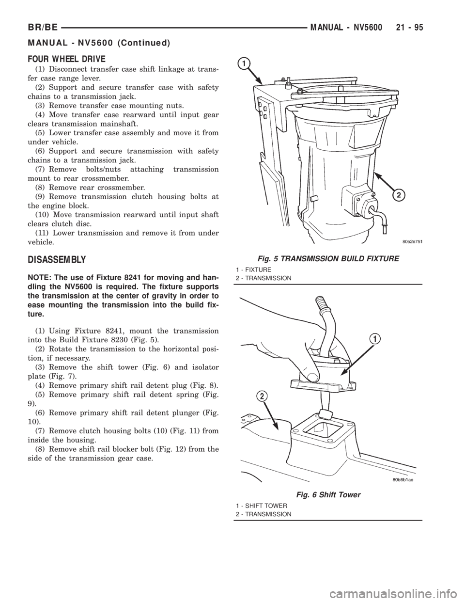
(1) Using Fixture 8241, mount the transmission
into the Build Fixture 8230 (Fig. 5).
(2) Rotate the transmission to the horizontal posi-
tion, if necessary.
(3) Remove the shift tower (Fig. 6) and isolator
plate (Fig. 7).
(4) Remove primary shift rail detent plug (Fig. 8).
(5) Remove primary shift rail detent spring (Fig.
9).
(6) Remove primary shift rail detent plunger (Fig.
10).
(7) Remove clutch housing bolts (10) (Fig. 11) from
inside the housing.
(8) Remove shift rail blocker bolt (Fig. 12) from the
side of the transmission gear case.
Fig. 5 TRANSMISSION BUILD FIXTURE
1 - FIXTURE
2 - TRANSMISSION
Fig. 6 Shift Tower
1 - SHIFT TOWER
2 - TRANSMISSION
BR/BEMANUAL - NV5600 21 - 95
MANUAL - NV5600 (Continued)