2001 DODGE RAM Body
[x] Cancel search: BodyPage 1 of 2889

GROUP TAB LOCATOR
Introduction
0Lubrication & Maintenance
2Suspension
3Differential & Driveline
5Brakes
7Cooling
8AAudio
8BChime/Buzzer
8EElectronic Control Modules
8FEngine Systems
8GHeated Systems
8HHorn
8IIgnition Control
8JInstrument Cluster
8LLamps
8MMessage Systems
8NPower Systems
8ORestraints
8PSpeed Control
8QVehicle Theft Security
8RWipers/Washers
8WWiring
9Engine
11Exhaust System
13Frame & Bumpers
14Fuel System
19Steering
21Transmission/Transaxle
22Tires/Wheels
23Body
24Heating & Air Conditioning
25Emissions Control Systems
30New Vehicle Preparation
Component and System Index
Service Manual Comment Forms (Rear of Manual)
Page 2 of 2889
INTRODUCTION
TABLE OF CONTENTS
page page
BODY CODE PLATE
DESCRIPTION............................1
FASTENER IDENTIFICATION
DESCRIPTION............................3
FASTENER USAGE
DESCRIPTION............................6
INTERNATIONAL VEHICLE CONTROL &
DISPLAY SYMBOLS
DESCRIPTION............................6
METRIC SYSTEM
DESCRIPTION............................6TORQUE REFERENCES
DESCRIPTION............................9
VECI LABEL
DESCRIPTION...........................10
OPERATION.............................10
VEHICLE IDENTIFICATION NUMBER
DESCRIPTION...........................10
VEHICLE SAFETY CERTIFICATION LABEL
DESCRIPTION...........................12
EQUIPMENT IDENTIFICATION PLATE
DESCRIPTION...........................12
BODY CODE PLATE
DESCRIPTION
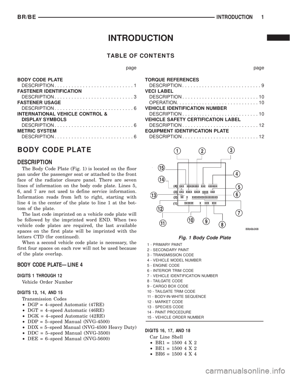
The Body Code Plate (Fig. 1) is located on the floor
pan under the passenger seat or attached to the front
face of the radiator closure panel. There are seven
lines of information on the body code plate. Lines 5,
6, and 7 are not used to define service information.
Information reads from left to right, starting with
line 4 in the center of the plate to line 1 at the bot-
tom of the plate.
The last code imprinted on a vehicle code plate will
be followed by the imprinted word END. When two
vehicle code plates are required, the last available
spaces on the first plate will be imprinted with the
letters CTD (for continued).
When a second vehicle code plate is necessary, the
first four spaces on each row will not be used because
of the plate overlap.
BODY CODE PLATEÐLINE 4
DIGITS 1 THROUGH 12
Vehicle Order Number
DIGITS 13, 14, AND 15
Transmission Codes
²DGP = 4±speed Automatic (47RE)
²DGT = 4±speed Automatic (46RE)
²DGK = 4±speed Automatic (42RE)
²DDP = 5±speed Manual (NVG-4500)
²DDX = 5±speed Manual (NVG-4500 Heavy Duty)
²DDC = 5±speed Manual (NVG-3500)
²DEE = 6±speed Manual (NVG-5600)DIGITS 16, 17, AND 18
Car Line Shell
²BR1=15004X2
²BE1=15004X2
²BR6=15004X4
Fig. 1 Body Code Plate
1 - PRIMARY PAINT
2 - SECONDARY PAINT
3 - TRANSMISSION CODE
4 - VEHICLE MODEL NUMBER
5 - ENGINE CODE
6 - INTERIOR TRIM CODE
7 - VEHICLE IDENTIFICATION NUMBER
8 - TAILGATE CODE
9 - CARGO BOX CODE
10 - TAILGATE TRIM CODE
11 - BODY-IN-WHITE SEQUENCE
12 - MARKET CODE
13 - SPECIES CODE
14 - PAINT PROCEDURE
15 - VEHICLE ORDER NUMBER
BR/BEINTRODUCTION 1
Page 3 of 2889
²BE6=15004X4
²BR2=25004X2
²BE2=25004X2
²BR7=25004X4
²BE7=25004X4
²BR3=35004X2
²BE3=35004X2
²BR8=35004X4
²BE8=35004X4
DIGIT 19
Price Class
²L = Ram Truck (All)
DIGITS 20 AND 21
Body Type
²
31 = Ram Truck Club Cab (138.7 in. Wheel Base)
²32 = Ram Truck Club Cab (154.7 in. Wheel Base)
²33 = Ram Truck Quad Cab (138.7 in. Wheel Base)
²34 = Ram Truck Quad Cab (154.7 in. Wheel Base)
²61 = Ram Truck (118.7 in. Wheel Base)
²62 = Ram Truck (134.7 in. Wheel Base)
²63 = Ram Truck Cab Chassis (138.7 in. Wheel
Base)
²
64 = Ram Truck Cab Chassis (162.7 in. Wheel
Base)
BODY CODE PLATEÐLINE 3
DIGITS 1,2, AND 3
Paint Procedure
²APA = Monotone
²AP9 = Special
²APB = Two-tone (Waterfall)
²APC = Two-tone (Centerband)
²APD = Two-tone (Lower break)
DIGIT 4
Open Space
DIGITS 5 THROUGH 8
Primary Paint
Refer to Group 23, Body for color codes.
DIGIT 9
Open Space
DIGITS 10 THROUGH 13
Secondary Paint
DIGIT 14
Open Space
DIGITS 15 THROUGH 18
Interior Trim CodeDIGIT 19
Open Space
DIGITS 20, 21, AND 22
Engine Code
²EHC = 3.9 L 6 cyl. MPI Gasoline
²ELF = 5.2 L 8 cyl. MPI Gasoline
²ELN = 5.2 L 8 cyl. (CNG)
²EML = 5.9 L 8 cyl. MPI Gasoline
²EMM = 5.9 L 8 cyl. MPI Gasoline (Heavy Duty)
²ETC = 5.9 L 6 cyl. Turbo Diesel
²EWA = 8.0 L 10 cyl. MPI Gasoline
BODY CODE PLATEÐLINE 2
DIGIT 1 Open Space
DIGITS 2 AND 3 Species Code. (Used for Manufacturing)
DIGIT 4
Open Space
DIGIT 5
Market Code
²B = International
²C = Canada
²M = Mexico
²U = United States
DIGIT 6
Open Space
DIGITS 7 THROUGH 23
Vehicle Identification Number (VIN)
Refer to Vehicle Identification Number (VIN) para-
graph for proper breakdown of VIN code.
BODY CODE PLATEÐLINE 1
DIGITS 1 THROUGH 6 Body-in-white assembly sequence.
DIGIT 7
Open Space
DIGIT 8 Tailgate trim code.
DIGIT 9
Open Space
DIGITS 10 THROUGH 12 Cargo box code
²XBS = Sweptline
DIGIT 13
Open Space
2 INTRODUCTIONBR/BE
BODY CODE PLATE (Continued)
Page 4 of 2889
DIGITS 14 THROUGH 16 Tailgate code
²MWD = Plain Tailgate
²MPB = Tailgate Applique (Black)
FASTENER IDENTIFICATION
DESCRIPTION
The SAE bolt strength grades range from grade 2
to grade 8. The higher the grade number, the greater
the bolt strength. Identification is determined by theline marks on the top of each bolt head. The actual
bolt strength grade corresponds to the number of line
marks plus 2. The most commonly used metric bolt
strength classes are 9.8 and 10.9. The metric
strength class identification number is imprinted on
the head of the bolt. The higher the class number,
the greater the bolt strength. Some metric nuts are
imprinted with a single-digit strength class on the
nut face. Refer to the Fastener Identification and
Fastener Strength Charts.
BR/BEINTRODUCTION 3
BODY CODE PLATE (Continued)
Page 11 of 2889
VECI LABEL
DESCRIPTION
Vehicles equipped with 3.9L V-6 or 5.2L/5.9L V-8
LDC-gas powered engines have a VECI label.
The label combines both emission control informa-
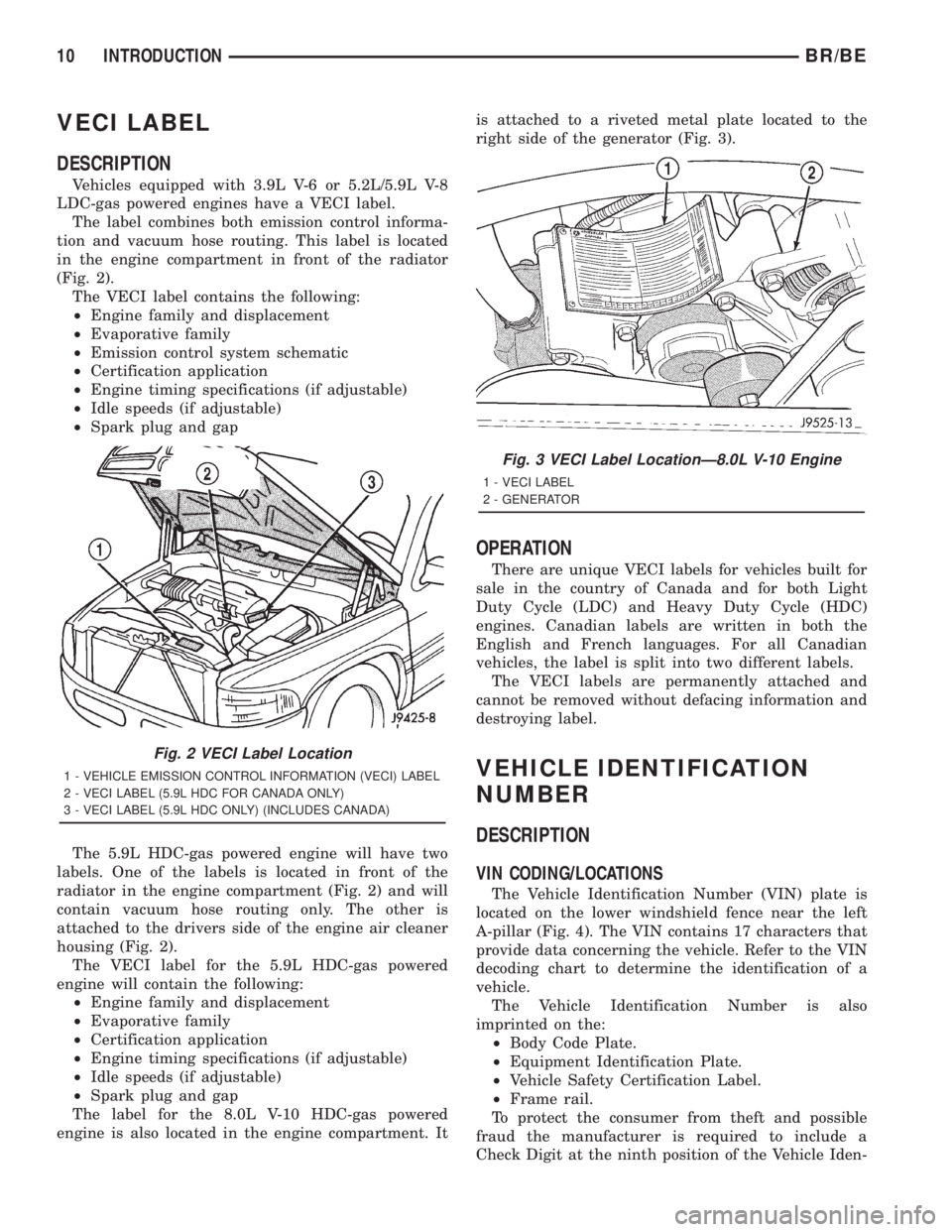
tion and vacuum hose routing. This label is located
in the engine compartment in front of the radiator
(Fig. 2).
The VECI label contains the following:
²Engine family and displacement
²Evaporative family
²Emission control system schematic
²Certification application
²Engine timing specifications (if adjustable)
²Idle speeds (if adjustable)
²Spark plug and gap
The 5.9L HDC-gas powered engine will have two
labels. One of the labels is located in front of the
radiator in the engine compartment (Fig. 2) and will
contain vacuum hose routing only. The other is
attached to the drivers side of the engine air cleaner
housing (Fig. 2).
The VECI label for the 5.9L HDC-gas powered
engine will contain the following:
²Engine family and displacement
²Evaporative family
²Certification application
²Engine timing specifications (if adjustable)
²Idle speeds (if adjustable)
²Spark plug and gap
The label for the 8.0L V-10 HDC-gas powered
engine is also located in the engine compartment. Itis attached to a riveted metal plate located to the
right side of the generator (Fig. 3).
OPERATION
There are unique VECI labels for vehicles built for
sale in the country of Canada and for both Light
Duty Cycle (LDC) and Heavy Duty Cycle (HDC)
engines. Canadian labels are written in both the
English and French languages. For all Canadian
vehicles, the label is split into two different labels.
The VECI labels are permanently attached and
cannot be removed without defacing information and
destroying label.
VEHICLE IDENTIFICATION
NUMBER
DESCRIPTION
VIN CODING/LOCATIONS
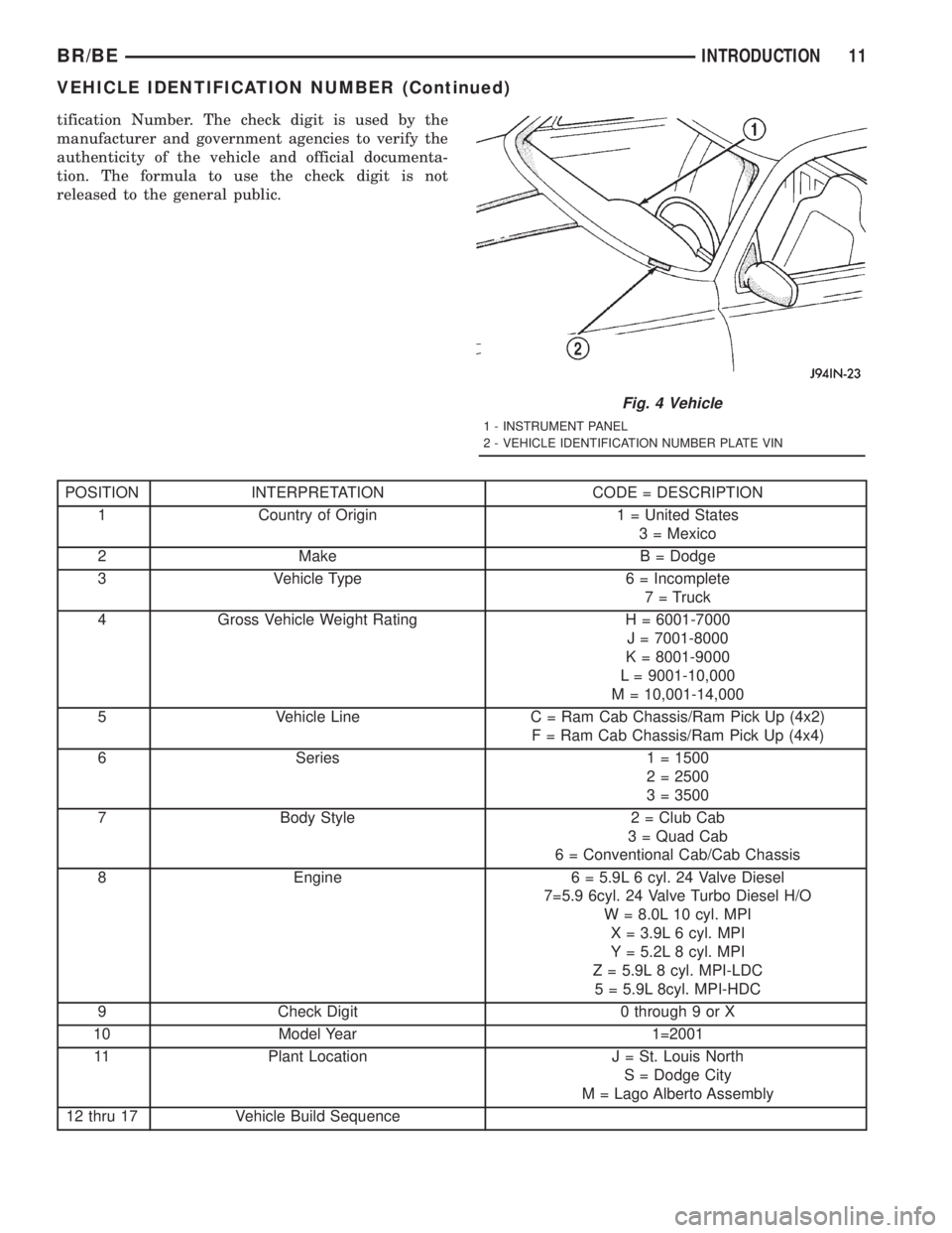
The Vehicle Identification Number (VIN) plate is
located on the lower windshield fence near the left
A-pillar (Fig. 4). The VIN contains 17 characters that
provide data concerning the vehicle. Refer to the VIN
decoding chart to determine the identification of a
vehicle.
The Vehicle Identification Number is also
imprinted on the:
²Body Code Plate.
²Equipment Identification Plate.
²Vehicle Safety Certification Label.
²Frame rail.
To protect the consumer from theft and possible
fraud the manufacturer is required to include a
Check Digit at the ninth position of the Vehicle Iden-
Fig. 2 VECI Label Location
1 - VEHICLE EMISSION CONTROL INFORMATION (VECI) LABEL
2 - VECI LABEL (5.9L HDC FOR CANADA ONLY)
3 - VECI LABEL (5.9L HDC ONLY) (INCLUDES CANADA)
Fig. 3 VECI Label LocationÐ8.0L V-10 Engine
1 - VECI LABEL
2 - GENERATOR
10 INTRODUCTIONBR/BE
Page 12 of 2889
tification Number. The check digit is used by the
manufacturer and government agencies to verify the
authenticity of the vehicle and official documenta-
tion. The formula to use the check digit is not
released to the general public.
POSITION INTERPRETATION CODE = DESCRIPTION
1 Country of Origin 1 = United States
3 = Mexico
2 Make B = Dodge
3 Vehicle Type 6 = Incomplete
7 = Truck
4 Gross Vehicle Weight Rating H = 6001-7000
J = 7001-8000
K = 8001-9000
L = 9001-10,000
M = 10,001-14,000
5 Vehicle Line C = Ram Cab Chassis/Ram Pick Up (4x2)
F = Ram Cab Chassis/Ram Pick Up (4x4)
6 Series 1 = 1500
2 = 2500
3 = 3500
7 Body Style 2 = Club Cab
3 = Quad Cab
6 = Conventional Cab/Cab Chassis
8 Engine 6 = 5.9L 6 cyl. 24 Valve Diesel
7=5.9 6cyl. 24 Valve Turbo Diesel H/O
W = 8.0L 10 cyl. MPI
X = 3.9L 6 cyl. MPI
Y = 5.2L 8 cyl. MPI
Z = 5.9L 8 cyl. MPI-LDC
5 = 5.9L 8cyl. MPI-HDC
9 Check Digit 0 through 9 or X
10 Model Year 1=2001
11 Plant Location J = St. Louis North
S = Dodge City
M = Lago Alberto Assembly
12 thru 17 Vehicle Build Sequence
Fig. 4 Vehicle
1 - INSTRUMENT PANEL
2 - VEHICLE IDENTIFICATION NUMBER PLATE VIN
BR/BEINTRODUCTION 11
VEHICLE IDENTIFICATION NUMBER (Continued)
Page 41 of 2889

DISCONNECT CABLE CLAMPS AS FOLLOWS:
²Disconnect BLACK cable clamp from engine
ground on disabled vehicle.
²When using a Booster vehicle, disconnect
BLACK cable clamp from battery negative terminal.
Disconnect RED cable clamp from battery positive
terminal.
²Disconnect RED cable clamp from battery posi-
tive terminal on disabled vehicle.
HOISTING
STANDARD PROCEDURE
Refer to the Owner's Manual for emergency vehicle
lifting procedures.
WARNING: THE HOISTING AND JACK LIFTING
POINTS PROVIDED ARE FOR A COMPLETE VEHI-
CLE. WHEN A CHASSIS OR DRIVETRAIN COMPO-
NENT IS REMOVED FROM A VEHICLE, THE
CENTER OF GRAVITY IS ALTERED MAKING SOME
HOISTING CONDITIONS UNSTABLE. PROPERLY
SUPPORT (Fig. 9) OR SECURE VEHICLE TO HOIST-
ING DEVICE WHEN THESE CONDITIONS EXIST.
FLOOR JACK
When properly positioned, a floor jack can be used
to lift a vehicle (Fig. 10). Support the vehicle in the
raised position with jack stands at the front and rear
ends of the frame rails (Fig. 9).CAUTION: Do not lift vehicle with a floor jack posi-
tioned under:
²An axle tube.
²A body side sill.
²A steering linkage component.
²A drive shaft.
²The engine or transmission oil pan.
²The fuel tank.
²A front suspension arm.
NOTE: Use the correct frame rail lifting locations
only (Fig. 11).
HOIST
A vehicle can be lifted with:
²A single-post, frame-contact hoist.
²A twin-post, chassis hoist.
²A ramp-type, drive-on hoist.
Fig. 8 Jumper Cable Clamp ConnectionsÐDiesel
Engine
1 - POSITIVE CABLE CONNECTION
2 - BATTERY
3 - NEGATIVE OR GROUND CABLE CONNECTION
Fig. 9 Safety Stands
1 - SAFETY STANDS
0 - 28 LUBRICATION & MAINTENANCEBR/BE
JUMP STARTING (Continued)
Page 55 of 2889
(3) Remove the brake caliper assembly and rotor,
(Refer to 5 - BRAKES/HYDRAULIC/MECHANICAL/
ROTORS - REMOVAL).
(4) Remove the cotter pin and nut from the tie rod.
Remove the tie rod end from the steering knuckle
with Puller C-3894-A.
(5) Remove the stabilizer bar link from the lower
suspension arm.
(6) Support the lower suspension arm outboard
end with a jack. Place a jack under the arm in front
of the shock mount.
(7) Remove the cotter pin and nut from the lower
ball joint. Separate the ball joint with Remover
C-4150A.
(8) Remove the lower shock bolt from the suspen-
sion arm.
(9) Lower the jack and suspension arm until
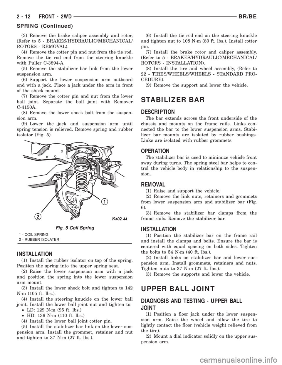
spring tension is relieved. Remove spring and rubber
isolator (Fig. 5).
INSTALLATION
(1) Install the rubber isolator on top of the spring.
Position the spring into the upper spring seat.
(2) Raise the lower suspension arm with a jack
and position the spring into the lower suspension
arm mount.
(3) Install the lower shock bolt and tighten to 142
N´m (105 ft. lbs.).
(4) Install the steering knuckle on the lower ball
joint. Install the lower ball joint nut and tighten to:
²LD: 129 N´m (95 ft. lbs.)
²HD: 136 N´m (110 ft. lbs.)
(4) Install the lower ball joint cotter pin.
(5) Install the stabilizer bar link on the lower sus-
pension arm. Install the grommet, retainer and nut
and tighten to 37 N´m (27 ft. lbs.).(6) Install the tie rod end on the steering knuckle
and tighten nut to 108 N´m (80 ft. lbs.). Install cotter
pin.
(7) Install the brake rotor and caliper assembly,
(Refer to 5 - BRAKES/HYDRAULIC/MECHANICAL/
ROTORS - INSTALLATION).
(8) Install the tire and wheel assembly, (Refer to
22 - TIRES/WHEELS/WHEELS - STANDARD PRO-
CEDURE).
(9) Remove the support and lower the vehicle.
STABILIZER BAR
DESCRIPTION
The bar extends across the front underside of the
chassis and mounts on the frame rails. Links con-
nected the bar to the lower suspension arms. Stabi-
lizer bar mounts are isolated by rubber bushings.
Links are isolated with rubber grommets.
OPERATION
The stabilizer bar is used to minimize vehicle front
sway during turns. The spring steel bar helps to con-
trol the vehicle body in relationship to the suspen-
sion.
REMOVAL
(1) Raise and support the vehicle.
(2) Remove the link nuts, retainers and grommets
from lower suspension arm and stabilizer bar (Fig.
6).
(3) Remove the stabilizer bar clamps from the
frame rails. Remove the stabilizer bar.
INSTALLATION
(1) Position the stabilizer bar on the frame rail
and install the clamps and bolts. Ensure the bar is
centered with equal spacing on both sides. Tighten
the bolts to 54 N´m (40 ft. lbs.).
(2) Install links on stabilizer bar and lower sus-
pension arm. Install grommets, retainers and nuts.
Tighten nuts to 37 N´m (27 ft. lbs.).
(3) Remove the supports and lower the vehicle.
UPPER BALL JOINT
DIAGNOSIS AND TESTING - UPPER BALL
JOINT
(1) Position a floor jack under the lower suspen-
sion arm. Raise the wheel and allow the tire to
lightly contact the floor (vehicle weight relieved from
the tire).
(2) Mount a dial indicator solidly on the upper sus-
pension arm.
Fig. 5 Coil Spring
1 - COIL SPRING
2 - RUBBER ISOLATER
2 - 12 FRONT - 2WDBR/BE
SPRING (Continued)