2001 DODGE RAM fuel cap
[x] Cancel search: fuel capPage 1508 of 2889
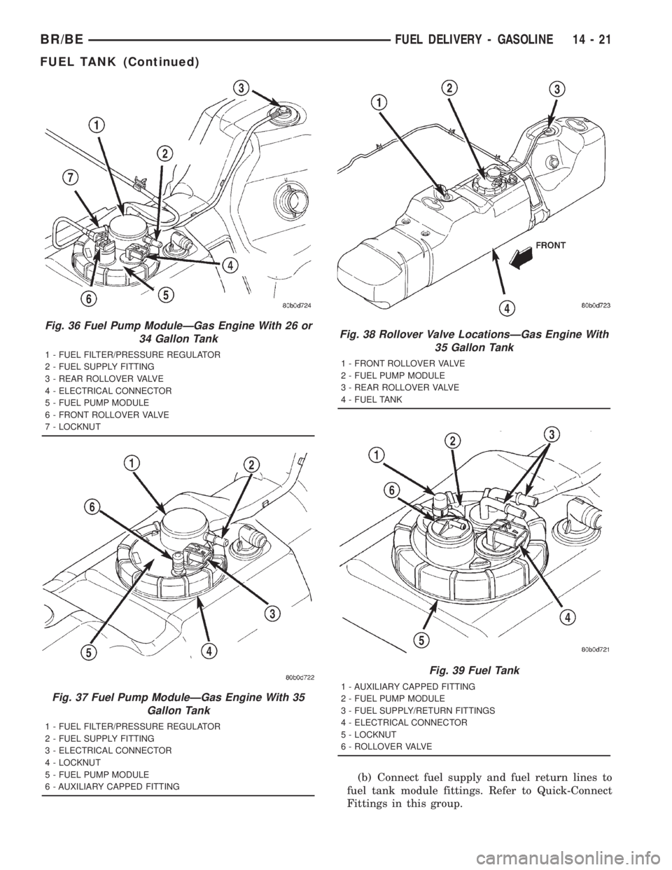
(b) Connect fuel supply and fuel return lines to
fuel tank module fittings. Refer to Quick-Connect
Fittings in this group.
Fig. 36 Fuel Pump ModuleÐGas Engine With 26 or
34 Gallon Tank
1 - FUEL FILTER/PRESSURE REGULATOR
2 - FUEL SUPPLY FITTING
3 - REAR ROLLOVER VALVE
4 - ELECTRICAL CONNECTOR
5 - FUEL PUMP MODULE
6 - FRONT ROLLOVER VALVE
7 - LOCKNUT
Fig. 37 Fuel Pump ModuleÐGas Engine With 35
Gallon Tank
1 - FUEL FILTER/PRESSURE REGULATOR
2 - FUEL SUPPLY FITTING
3 - ELECTRICAL CONNECTOR
4 - LOCKNUT
5 - FUEL PUMP MODULE
6 - AUXILIARY CAPPED FITTING
Fig. 38 Rollover Valve LocationsÐGas Engine With
35 Gallon Tank
1 - FRONT ROLLOVER VALVE
2 - FUEL PUMP MODULE
3 - REAR ROLLOVER VALVE
4 - FUEL TANK
Fig. 39 Fuel Tank
1 - AUXILIARY CAPPED FITTING
2 - FUEL PUMP MODULE
3 - FUEL SUPPLY/RETURN FITTINGS
4 - ELECTRICAL CONNECTOR
5 - LOCKNUT
6 - ROLLOVER VALVE
BR/BEFUEL DELIVERY - GASOLINE 14 - 21
FUEL TANK (Continued)
Page 1512 of 2889
(b) Type 2: Separate and unlatch 2 small arms
on end of clip (Fig. 47) and swing away from fuel
line.
(c) Slide latch clip toward fuel rail while lifting
with screwdriver.
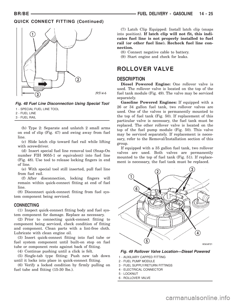
(d) Insert special fuel line removal tool (Snap-On
number FIH 9055-1 or equivalent) into fuel line
(Fig. 48). Use tool to release locking fingers in end
of line.
(e) With special tool still inserted, pull fuel line
from fuel rail.
(f) After disconnection, locking fingers will
remain within quick-connect fitting at end of fuel
line.
(8) Disconnect quick-connect fitting from fuel sys-
tem component being serviced.
CONNECTING
(1) Inspect quick-connect fitting body and fuel sys-
tem component for damage. Replace as necessary.
(2) Prior to connecting quick-connect fitting to
component being serviced, check condition of fitting
and component. Clean parts with a lint-free cloth.
Lubricate with clean engine oil.
(3) Insert quick-connect fitting into fuel tube or
fuel system component until built-on stop on fuel
tube or component rests against back of fitting.
(4) Continue pushing until a click is felt.
(5) Single-tab type fitting: Push new tab down
until it locks into place in quick-connect fitting.
(6) Verify a locked condition by firmly pulling on
fuel tube and fitting (15-30 lbs.).(7) Latch Clip Equipped: Install latch clip (snaps
into position).If latch clip will not fit, this indi-
cates fuel line is not properly installed to fuel
rail (or other fuel line). Recheck fuel line con-
nection.
(8) Connect negative cable to battery.
(9) Start engine and check for leaks.
ROLLOVER VALVE
DESCRIPTION
Diesel Powered Engine:One rollover valve is
used. The rollover valve is located on the top of the
fuel tank module (Fig. 49). The valve may be serviced
separately.
Gasoline Powered Engines:If equipped with a
26 or 34 gallon fuel tank, two rollover valves are
used. One of the valves is permanently mounted to
the top of fuel tank (Fig. 50). If replacement of this
particular valve is necessary, the fuel tank must be
replaced. The other rollover valve is located on the
top of the fuel pump module (Fig. 50). This valve
may be serviced separately. If replacement is neces-
sary, refer to the Removal/Installation section of this
group.
If equipped with a 35 gallon fuel tank, two rollover
valves are used. Both valves are permanently
mounted to the top of fuel tank (Fig. 51). If replace-
ment is necessary, the fuel tank must be replaced.
Fig. 48 Fuel Line Disconnection Using Special Tool
1 - SPECIAL FUEL LINE TOOL
2 - FUEL LINE
3 - FUEL RAIL
Fig. 49 Rollover Valve LocationÐDiesel Powered
1 - AUXILIARY CAPPED FITTING
2 - FUEL PUMP MODULE
3 - FUEL SUPPLY/RETURN FITTINGS
4 - ELECTRICAL CONNECTOR
5 - LOCKNUT
6 - ROLLOVER VALVE
BR/BEFUEL DELIVERY - GASOLINE 14 - 25
QUICK CONNECT FITTING (Continued)
Page 1513 of 2889
REMOVAL
WARNING: THE FUEL SYSTEM IS UNDER A CON-
STANT PRESSURE (EVEN WITH THE ENGINE OFF).
BEFORE SERVICING THE ROLLOVER VALVE, FUEL
SYSTEM PRESSURE MUST BE RELEASED (GASO-
LINE POWERED ENGINES ONLY). REFER TO THE
FUEL PRESSURE RELEASE PROCEDURE IN
GROUP 14, FUEL SYSTEM.
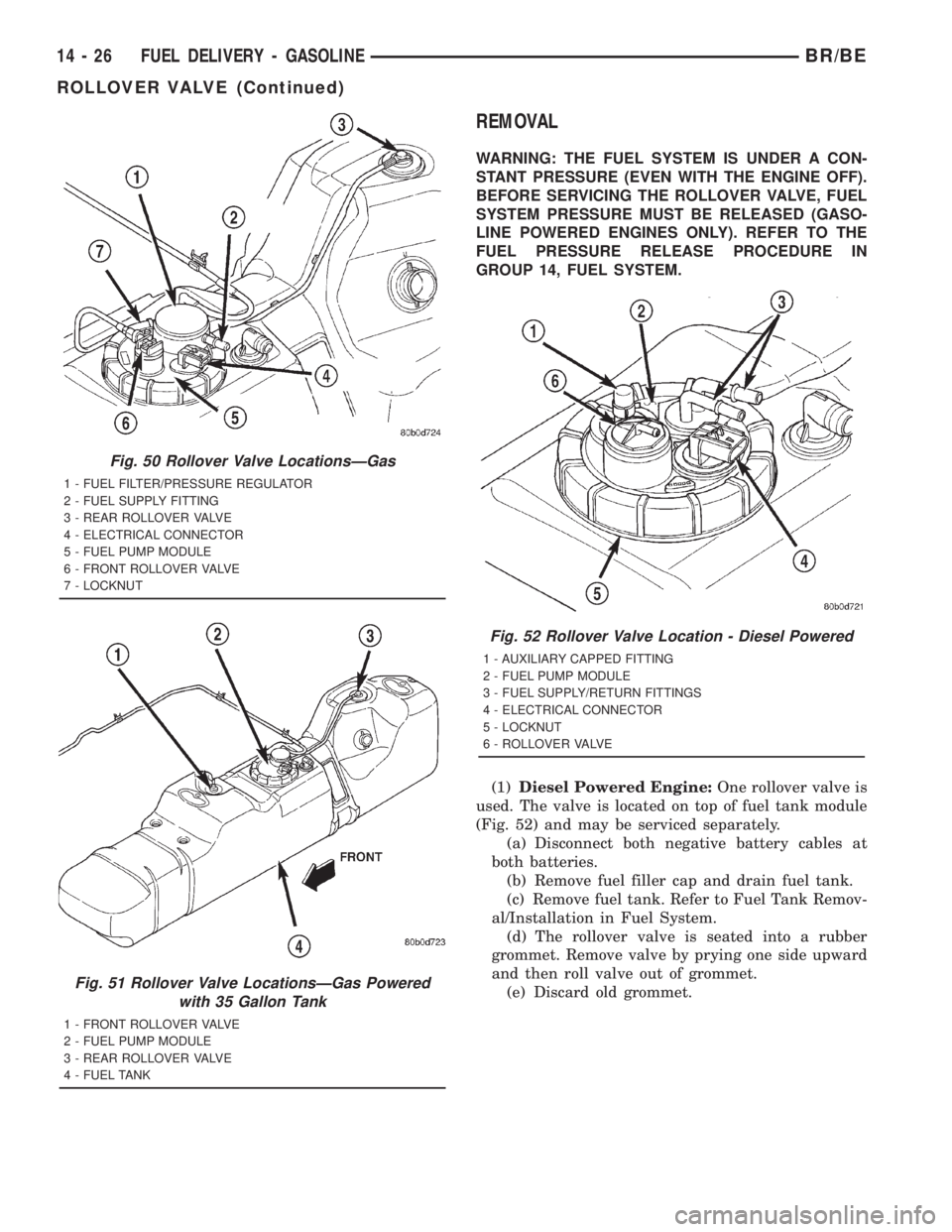
(1)Diesel Powered Engine:One rollover valve is
used. The valve is located on top of fuel tank module
(Fig. 52) and may be serviced separately.
(a) Disconnect both negative battery cables at
both batteries.
(b) Remove fuel filler cap and drain fuel tank.
(c) Remove fuel tank. Refer to Fuel Tank Remov-
al/Installation in Fuel System.
(d) The rollover valve is seated into a rubber
grommet. Remove valve by prying one side upward
and then roll valve out of grommet.
(e) Discard old grommet.
Fig. 50 Rollover Valve LocationsÐGas
1 - FUEL FILTER/PRESSURE REGULATOR
2 - FUEL SUPPLY FITTING
3 - REAR ROLLOVER VALVE
4 - ELECTRICAL CONNECTOR
5 - FUEL PUMP MODULE
6 - FRONT ROLLOVER VALVE
7 - LOCKNUT
Fig. 51 Rollover Valve LocationsÐGas Powered
with 35 Gallon Tank
1 - FRONT ROLLOVER VALVE
2 - FUEL PUMP MODULE
3 - REAR ROLLOVER VALVE
4 - FUEL TANK
Fig. 52 Rollover Valve Location - Diesel Powered
1 - AUXILIARY CAPPED FITTING
2 - FUEL PUMP MODULE
3 - FUEL SUPPLY/RETURN FITTINGS
4 - ELECTRICAL CONNECTOR
5 - LOCKNUT
6 - ROLLOVER VALVE
14 - 26 FUEL DELIVERY - GASOLINEBR/BE
ROLLOVER VALVE (Continued)
Page 1514 of 2889
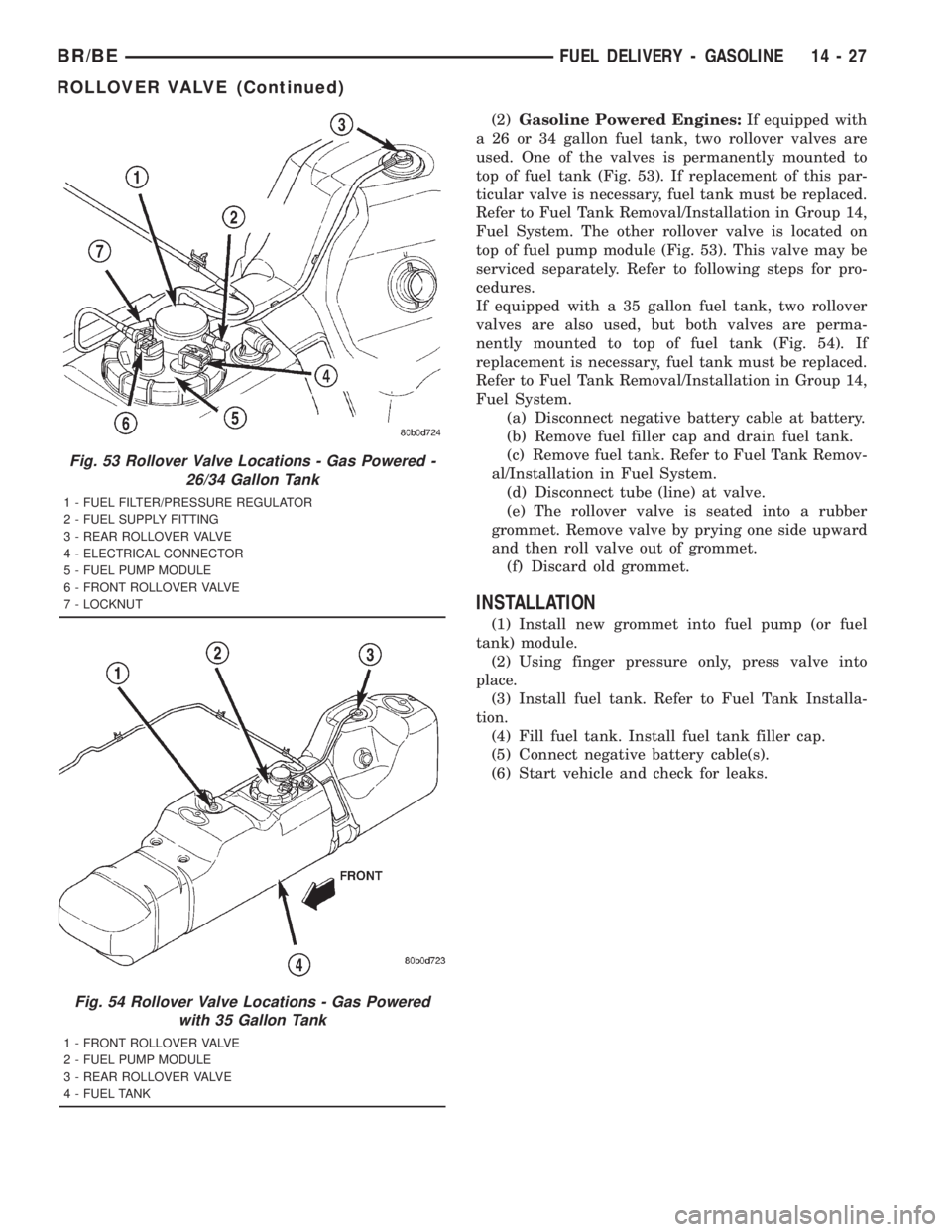
(2)Gasoline Powered Engines:If equipped with
a 26 or 34 gallon fuel tank, two rollover valves are
used. One of the valves is permanently mounted to
top of fuel tank (Fig. 53). If replacement of this par-
ticular valve is necessary, fuel tank must be replaced.
Refer to Fuel Tank Removal/Installation in Group 14,
Fuel System. The other rollover valve is located on
top of fuel pump module (Fig. 53). This valve may be
serviced separately. Refer to following steps for pro-
cedures.
If equipped with a 35 gallon fuel tank, two rollover
valves are also used, but both valves are perma-
nently mounted to top of fuel tank (Fig. 54). If
replacement is necessary, fuel tank must be replaced.
Refer to Fuel Tank Removal/Installation in Group 14,
Fuel System.
(a) Disconnect negative battery cable at battery.
(b) Remove fuel filler cap and drain fuel tank.
(c) Remove fuel tank. Refer to Fuel Tank Remov-
al/Installation in Fuel System.
(d) Disconnect tube (line) at valve.
(e) The rollover valve is seated into a rubber
grommet. Remove valve by prying one side upward
and then roll valve out of grommet.
(f) Discard old grommet.
INSTALLATION
(1) Install new grommet into fuel pump (or fuel
tank) module.
(2) Using finger pressure only, press valve into
place.
(3) Install fuel tank. Refer to Fuel Tank Installa-
tion.
(4) Fill fuel tank. Install fuel tank filler cap.
(5) Connect negative battery cable(s).
(6) Start vehicle and check for leaks.
Fig. 53 Rollover Valve Locations - Gas Powered -
26/34 Gallon Tank
1 - FUEL FILTER/PRESSURE REGULATOR
2 - FUEL SUPPLY FITTING
3 - REAR ROLLOVER VALVE
4 - ELECTRICAL CONNECTOR
5 - FUEL PUMP MODULE
6 - FRONT ROLLOVER VALVE
7 - LOCKNUT
Fig. 54 Rollover Valve Locations - Gas Powered
with 35 Gallon Tank
1 - FRONT ROLLOVER VALVE
2 - FUEL PUMP MODULE
3 - REAR ROLLOVER VALVE
4 - FUEL TANK
BR/BEFUEL DELIVERY - GASOLINE 14 - 27
ROLLOVER VALVE (Continued)
Page 1516 of 2889
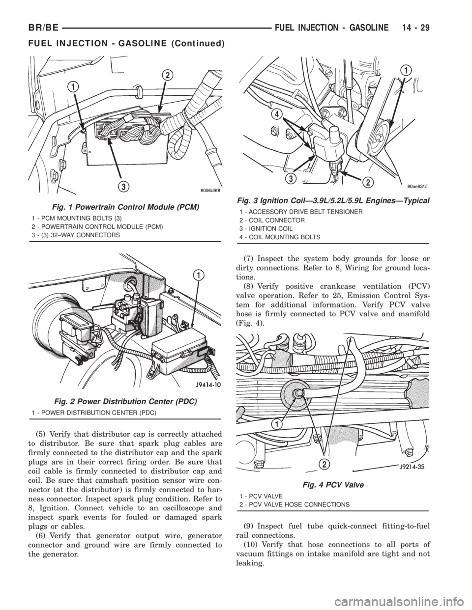
(5) Verify that distributor cap is correctly attached
to distributor. Be sure that spark plug cables are
firmly connected to the distributor cap and the spark
plugs are in their correct firing order. Be sure that
coil cable is firmly connected to distributor cap and
coil. Be sure that camshaft position sensor wire con-
nector (at the distributor) is firmly connected to har-
ness connector. Inspect spark plug condition. Refer to
8, Ignition. Connect vehicle to an oscilloscope and
inspect spark events for fouled or damaged spark
plugs or cables.
(6) Verify that generator output wire, generator
connector and ground wire are firmly connected to
the generator.(7) Inspect the system body grounds for loose or
dirty connections. Refer to 8, Wiring for ground loca-
tions.
(8) Verify positive crankcase ventilation (PCV)
valve operation. Refer to 25, Emission Control Sys-
tem for additional information. Verify PCV valve
hose is firmly connected to PCV valve and manifold
(Fig. 4).
(9) Inspect fuel tube quick-connect fitting-to-fuel
rail connections.
(10) Verify that hose connections to all ports of
vacuum fittings on intake manifold are tight and not
leaking.
Fig. 1 Powertrain Control Module (PCM)
1 - PCM MOUNTING BOLTS (3)
2 - POWERTRAIN CONTROL MODULE (PCM)
3 - (3) 32±WAY CONNECTORS
Fig. 2 Power Distribution Center (PDC)
1 - POWER DISTRIBUTION CENTER (PDC)
Fig. 3 Ignition CoilÐ3.9L/5.2L/5.9L EnginesÐTypical
1 - ACCESSORY DRIVE BELT TENSIONER
2 - COIL CONNECTOR
3 - IGNITION COIL
4 - COIL MOUNTING BOLTS
Fig. 4 PCV Valve
1 - P C V VA LV E
2 - PCV VALVE HOSE CONNECTIONS
BR/BEFUEL INJECTION - GASOLINE 14 - 29
FUEL INJECTION - GASOLINE (Continued)
Page 1543 of 2889
²Fuel filter/water separator
²Fuel heater
²Fuel heater relay
²Fuel transfer (lift) pump
²Fuel injection pump
²Fuel injectors
²Fuel heater temperature sensor
²Fuel tank
²Fuel tank filler/vent tube assembly
²Fuel tank filler tube cap
²Fuel tank module containing the rollover valve,
fuel gauge sending unit (fuel level sensor) and a sep-
arate fuel filter located at bottom of tank module
²Fuel tubes/lines/hoses
²High-pressure fuel injector lines
²In-tank fuel filter (at bottom of fuel tank mod-
ule)
²Low-pressure fuel supply lines
²Low-pressure fuel return line
²Overflow valve
²Quick-connect fittings
²Throttle cable
²Water draining
OPERATION
WARNING: HIGH-PRESSURE FUEL LINES DELIVER
DIESEL FUEL UNDER EXTREME PRESSURE FROM
THE INJECTION PUMP TO THE FUEL INJECTORS.
THIS MAY BE AS HIGH AS 120,000 KPA (17,405
PSI). USE EXTREME CAUTION WHEN INSPECTING
FOR HIGH-PRESSURE FUEL LEAKS. INSPECT FOR
HIGH-PRESSURE FUEL LEAKS WITH A SHEET OF
CARDBOARD. HIGH FUEL INJECTION PRESSURE
CAN CAUSE PERSONAL INJURY IF CONTACT IS
MADE WITH THE SKIN.
DIAGNOSIS AND TESTING - AIR IN FUEL
SYSTEM
Air will enter the fuel system whenever fuel supply
lines, separator filters, injection pump, high-pressure
lines or injectors are removed or disconnected. Air
trapped in the fuel system can result in hard start-
ing, a rough running engine, engine misfire, low
power, excessive smoke and fuel knock. After service
is performed, air must be bled from the system
before starting the engine.Inspect the fuel system from the fuel transfer
pump to the injectors for loose connections. Leaking
fuel is an indicator of loose connections or defective
seals. Air can also enter the fuel system between the
fuel tank and the transfer pump. Inspect the fuel
tank and fuel lines for damage that might allow air
into the system.
For air bleeding, refer to the Air Bleed Procedure.
DIAGNOSIS AND TESTING - FUEL SUPPLY
RESTRICTIONS
LOW-PRESSURE LINES
Fuel supply line restrictions or a defective fuel
transfer pump can cause starting problems and pre-
vent engine from accelerating. The starting problems
include; low power and/or white fog like exhaust.
Test all fuel supply lines for restrictions or block-
age. Flush or replace as necessary. Bleed fuel system
of air once a fuel supply line has been replaced. Refer
to Air Bleed Procedure for procedures.
To test for fuel line restrictions, a vacuum restric-
tion test may be performed. Refer to Fuel Transfer
Pump Pressure Test.
HIGH-PRESSURE LINES
Restricted (kinked or bent) high-pressure lines can
cause starting problems, poor engine performance,
engine mis-fire and white smoke from exhaust.
Examine all high-pressure lines for any damage.
Each radius on each high-pressure line must be
smooth and free of any bends or kinks.
Replace damaged, restricted or leaking high-pres-
sure fuel lines with correct replacement line.
CAUTION: All high-pressure fuel lines must be
clamped securely in place in holders. Lines cannot
contact each other or other components. Do not
attempt to weld high-pressure fuel lines or to repair
lines that are damaged. If line is kinked or bent, it
must be replaced. Use only recommended lines
when replacement of high-pressure fuel line is nec-
essary.
STANDARD PROCEDURES - WATER DRAINING
AT FUEL FILTER
Refer to Fuel Filter/Water Separator removal/in-
stallation for procedures.
14 - 56 FUEL DELIVERY - DIESELBR/BE
FUEL DELIVERY - DIESEL (Continued)
Page 1544 of 2889
STANDARD PROCEDURES - CLEANING FUEL
SYSTEM PARTS
CAUTION: Cleanliness cannot be overemphasized
when handling or replacing diesel fuel system com-
ponents. This especially includes the fuel injectors,
high-pressure fuel lines and fuel injection pump.
Very tight tolerances are used with these parts. Dirt
contamination could cause rapid part wear and pos-
sible plugging of fuel injector nozzle tip holes. This
in turn could lead to possible engine misfire.
Always wash/clean any fuel system component
thoroughly before disassembly and then air dry.
Cap or cover any open part after disassembly.
Before assembly, examine each part for dirt, grease
or other contaminants and clean if necessary. When
installing new parts, lubricate them with clean
engine oil or clean diesel fuel only.
STANDARD PROCEDURE - AIR BLEED
A certain amount of air becomes trapped in the
fuel system when fuel system components on the
supply and/or high-pressure side are serviced or
replaced. Primary air bleeding is accomplished using
the electric fuel transfer (lift) pump. If the vehicle
has been allowed to run completely out of fuel, the
fuel injectors must also be bled as the fuel injection
pumpis notself-bleeding (priming).
Servicing or replacing components on the fuel
return side will not require air bleeding.
WARNING: DO NOT BLEED AIR FROM THE FUEL
SYSTEM OF A HOT ENGINE.
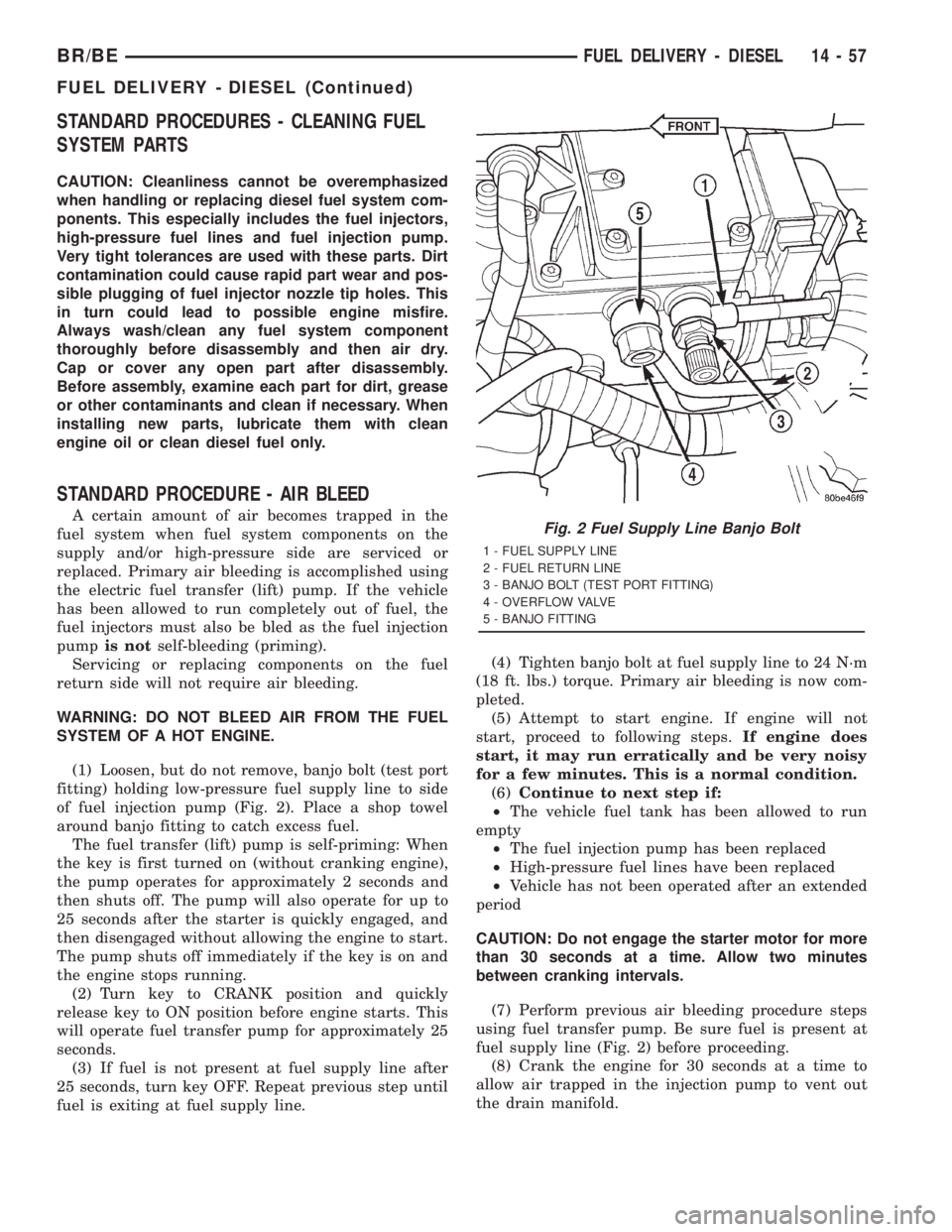
(1) Loosen, but do not remove, banjo bolt (test port
fitting) holding low-pressure fuel supply line to side
of fuel injection pump (Fig. 2). Place a shop towel
around banjo fitting to catch excess fuel.
The fuel transfer (lift) pump is self-priming: When
the key is first turned on (without cranking engine),
the pump operates for approximately 2 seconds and
then shuts off. The pump will also operate for up to
25 seconds after the starter is quickly engaged, and
then disengaged without allowing the engine to start.
The pump shuts off immediately if the key is on and
the engine stops running.
(2) Turn key to CRANK position and quickly
release key to ON position before engine starts. This
will operate fuel transfer pump for approximately 25
seconds.
(3) If fuel is not present at fuel supply line after
25 seconds, turn key OFF. Repeat previous step until
fuel is exiting at fuel supply line.(4) Tighten banjo bolt at fuel supply line to 24 N´m
(18 ft. lbs.) torque. Primary air bleeding is now com-
pleted.
(5) Attempt to start engine. If engine will not
start, proceed to following steps.If engine does
start, it may run erratically and be very noisy
for a few minutes. This is a normal condition.
(6)Continue to next step if:
²The vehicle fuel tank has been allowed to run
empty
²The fuel injection pump has been replaced
²High-pressure fuel lines have been replaced
²Vehicle has not been operated after an extended
period
CAUTION: Do not engage the starter motor for more
than 30 seconds at a time. Allow two minutes
between cranking intervals.
(7) Perform previous air bleeding procedure steps
using fuel transfer pump. Be sure fuel is present at
fuel supply line (Fig. 2) before proceeding.
(8) Crank the engine for 30 seconds at a time to
allow air trapped in the injection pump to vent out
the drain manifold.Fig. 2 Fuel Supply Line Banjo Bolt
1 - FUEL SUPPLY LINE
2 - FUEL RETURN LINE
3 - BANJO BOLT (TEST PORT FITTING)
4 - OVERFLOW VALVE
5 - BANJO FITTING
BR/BEFUEL DELIVERY - DIESEL 14 - 57
FUEL DELIVERY - DIESEL (Continued)
Page 1547 of 2889
REMOVAL
Refer to maintenance schedules in this manual for
recommended fuel filter replacement intervals.
Draining water from fuel filter/water separa-
tor housing:
The housing drain valve (Fig. 5) serves two pur-
poses. One is topartiallydrain filter housing of
excess water. The other is tocompletelydrain hous-
ing for fuel filter, drain valve, heater element or
water-in-fuel sensor replacement.
The filter housing should be drained whenever
water-in-fuel warning lamp remains illuminated.
(Note that lamp will be illuminated for approxi-
mately two seconds when ignition key is initially
placed in ON position for a bulb check).
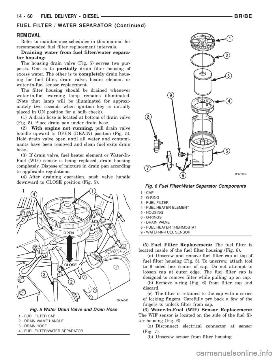
(1) A drain hose is located at bottom of drain valve
(Fig. 5). Place drain pan under drain hose.
(2)With engine not running,pull drain valve
handle upward to OPEN (DRAIN) position (Fig. 5).
Hold drain valve open until all water and contami-
nants have been removed and clean fuel exits drain
hose.
(3) If drain valve, fuel heater element or Water-In-
Fuel (WIF) sensor is being replaced, drain housing
completely. Dispose of mixture in drain pan according
to applicable regulations.
(4) After draining operation, push valve handle
downward to CLOSE position (Fig. 5).
(5)Fuel Filter Replacement:The fuel filter is
located inside of the fuel filter housing (Fig. 6).
(a) Unscrew and remove fuel filter cap at top of
fuel filter housing (Fig. 5). To unscrew, attach tool
to 6±sided hex center of cap. Do not attempt to
loosen cap at outer edge. The fuel filter cap is
designed to remove filter while pulling up on cap.
(b) Remove o-ring (Fig. 6) from filter cap and
discard.
(c) The filter is retained to the cap with a series
of locking fingers. Carefully pry back a few of the
fingers to unlock filter from cap.
(6)Water-In-Fuel (WIF) Sensor Replacement:
The WIF sensor is located on the side of the fuel fil-
ter housing (Fig. 6).
(a) Disconnect electrical connector at sensor
(Fig. 7).
(b) Unscrew sensor from filter housing.
Fig. 5 Water Drain Valve and Drain Hose
1 - FUEL FILTER CAP
2 - DRAIN VALVE HANDLE
3 - DRAIN HOSE
4 - FUEL FILTER/WATER SEPARATOR
Fig. 6 Fuel Filter/Water Separator Components
1 - CAP
2 - O-RING
3 - FUEL FILTER
4 - FUEL HEATER ELEMENT
5 - HOUSING
6 - O-RINGS
7 - DRAIN VALVE
8 - FUEL HEATER THERMOSTAT
9 - WATER-IN-FUEL SENSOR
14 - 60 FUEL DELIVERY - DIESELBR/BE
FUEL FILTER / WATER SEPARATOR (Continued)