2001 DODGE RAM intake manifold
[x] Cancel search: intake manifoldPage 1165 of 2889
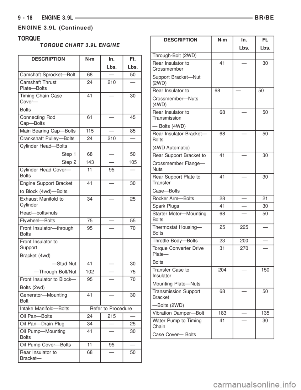
TORQUE
TORQUE CHART 3.9L ENGINE
DESCRIPTION N´m In. Ft.
Lbs. Lbs.
Camshaft SprocketÐBolt 68 Ð 50
Camshaft Thrust
PlateÐBolts24 210 Ð
Timing Chain Case
CoverÐ41 Ð 30
Bolts
Connecting Rod
CapÐBolts61 Ð 45
Main Bearing CapÐBolts 115 Ð 85
Crankshaft PulleyÐBolts 24 210 Ð
Cylinder HeadÐBolts
Step 1 68 Ð 50
Step 2 143 Ð 105
Cylinder Head CoverÐ
Bolts11 95 Ð
Engine Support Bracket 41 Ð 30
to Block (4wd)ÐBolts
Exhaust Manifold to
Cylinder34 Ð 25
HeadÐbolts/nuts
FlywheelÐBolts 75 Ð 55
Front InsulatorÐthrough
Bolts95 Ð 70
Front Insulator to
Support
Bracket (4wd)
ÐStud Nut 41 Ð 30
ÐThrough Bolt/Nut 102 Ð 75
Front Insulator to BlockÐ 95 Ð 70
Bolts (2wd)
GeneratorÐMounting
Bolt41 Ð 30
Intake ManifoldÐBolts Refer to Procedure
Oil PanÐBolts 24 215 Ð
Oil PanÐDrain Plug 34 Ð 25
Oil PumpÐMounting
Bolts41 Ð 30
Oil Pump CoverÐBolts 11 95 Ð
Rear Insulator to
BracketÐ68 Ð 50
DESCRIPTION N´m In. Ft.
Lbs. Lbs.
Through-Bolt (2WD)
Rear Insulator to
Crossmember41 Ð 30
Support BracketÐNut
(2WD)
Rear Insulator to 68 Ð 50
CrossmemberÐNuts
(4WD)
Rear Insulator to
Transmission68 Ð 50
Ð Bolts (4WD)
Rear Insulator BracketÐ
Bolts68 Ð 50
(4WD Automatic)
Rear Support Bracket to 41 Ð 30
Crossmember FlangeÐ
Nuts
Rear Support Plate to
Transfer41 Ð 30
CaseÐBolts
Rocker ArmÐBolts 28 Ð 21
Spark Plugs 41 Ð 30
Starter MotorÐMounting
Bolts68 Ð 50
Thermostat HousingÐ
Bolts25 225 Ð
Throttle BodyÐBolts 23 200 Ð
Torque Converter Drive
PlateÐ31 270 Ð
Bolts
Transfer Case to
Insulator204 Ð 150
Mounting PlateÐNuts
Transmission Support
Bracket68 Ð 50
ÐBolts (2WD)
Vibration DamperÐBolt 183 Ð 135
Water Pump to Timing
Chain41 Ð 30
Case CoverÐ Bolts
9 - 18 ENGINE 3.9LBR/BE
ENGINE 3.9L (Continued)
Page 1168 of 2889
AIR CLEANER ELEMENT
REMOVAL - 3.9L/5.2L/5.9L
For air cleaner element required maintenance
schedules (listed in time or mileage intervals), refer
to 0, Lubrication and Maintenance.
CAUTION: Do not attempt to remove air cleaner ele-
ment (filter) from housing by removing top cover
only. To prevent damage to air cleaner housing, the
entire air cleaner housing assembly must be
removed from engine for air cleaner element
replacement.
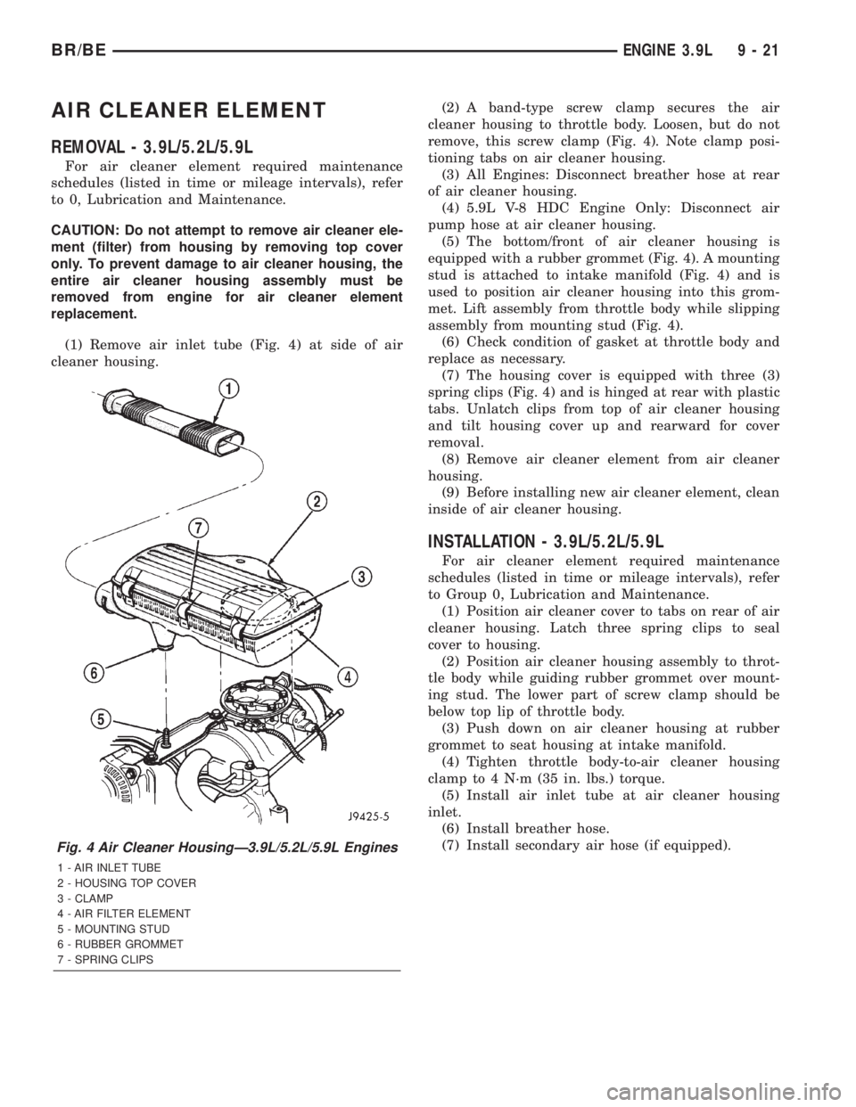
(1) Remove air inlet tube (Fig. 4) at side of air
cleaner housing.(2) A band-type screw clamp secures the air
cleaner housing to throttle body. Loosen, but do not
remove, this screw clamp (Fig. 4). Note clamp posi-
tioning tabs on air cleaner housing.
(3) All Engines: Disconnect breather hose at rear
of air cleaner housing.
(4) 5.9L V-8 HDC Engine Only: Disconnect air
pump hose at air cleaner housing.
(5) The bottom/front of air cleaner housing is
equipped with a rubber grommet (Fig. 4). A mounting
stud is attached to intake manifold (Fig. 4) and is
used to position air cleaner housing into this grom-
met. Lift assembly from throttle body while slipping
assembly from mounting stud (Fig. 4).
(6) Check condition of gasket at throttle body and
replace as necessary.
(7) The housing cover is equipped with three (3)
spring clips (Fig. 4) and is hinged at rear with plastic
tabs. Unlatch clips from top of air cleaner housing
and tilt housing cover up and rearward for cover
removal.
(8) Remove air cleaner element from air cleaner
housing.
(9) Before installing new air cleaner element, clean
inside of air cleaner housing.
INSTALLATION - 3.9L/5.2L/5.9L
For air cleaner element required maintenance
schedules (listed in time or mileage intervals), refer
to Group 0, Lubrication and Maintenance.
(1) Position air cleaner cover to tabs on rear of air
cleaner housing. Latch three spring clips to seal
cover to housing.
(2) Position air cleaner housing assembly to throt-
tle body while guiding rubber grommet over mount-
ing stud. The lower part of screw clamp should be
below top lip of throttle body.
(3) Push down on air cleaner housing at rubber
grommet to seat housing at intake manifold.
(4) Tighten throttle body-to-air cleaner housing
clamp to 4 N´m (35 in. lbs.) torque.
(5) Install air inlet tube at air cleaner housing
inlet.
(6) Install breather hose.
(7) Install secondary air hose (if equipped).
Fig. 4 Air Cleaner HousingÐ3.9L/5.2L/5.9L Engines
1 - AIR INLET TUBE
2 - HOUSING TOP COVER
3 - CLAMP
4 - AIR FILTER ELEMENT
5 - MOUNTING STUD
6 - RUBBER GROMMET
7 - SPRING CLIPS
BR/BEENGINE 3.9L 9 - 21
Page 1170 of 2889
COOLING SYSTEM TESTER METHOD
WARNING: WITH COOLING SYSTEM TESTER IN
PLACE, PRESSURE WILL BUILD UP FAST. EXCES-
SIVE PRESSURE BUILT UP, BY CONTINUOUS
ENGINE OPERATION, MUST BE RELEASED TO A
SAFE PRESSURE POINT. NEVER PERMIT PRES-
SURE TO EXCEED 138 kPa (20 psi).
Install Cooling System Tester 7700 or equivalent to
pressure cap neck. Start the engine and observe the
tester's pressure gauge. If gauge pulsates with every
power stroke of a cylinder a combustion pressure
leak is evident.
CHEMICAL TEST METHOD
Combustion leaks into the cooling system can also
be checked by using Bloc-Chek Kit C-3685-A or
equivalent. Perform test following the procedures
supplied with the tool kit.
REMOVAL
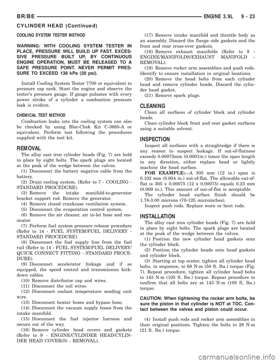
The alloy cast iron cylinder heads (Fig. 7) are held
in place by eight bolts. The spark plugs are located
at the peak of the wedge between the valves.
(1) Disconnect the battery negative cable from the
battery.
(2) Drain cooling system. (Refer to 7 - COOLING -
STANDARD PROCEDURE).
(3) Remove the intake manifold-to-generator
bracket support rod. Remove the generator.
(4) Remove closed crankcase ventilation system.
(5) Disconnect the evaporation control system.
(6) Remove the air cleaner, air in-let hose and res-
onator.
(7) Perform fuel system pressure release procedure
(Refer to 14 - FUEL SYSTEM/FUEL DELIVERY -
STANDARD PROCEDURE).
(8) Disconnect the fuel supply line from the fuel
rail (Refer to 14 - FUEL SYSTEM/FUEL DELIVERY/
QUICK CONNECT FITTING - STANDARD PROCE-
DURE).
(9) Disconnect accelerator linkage and if so
equipped, the speed control and transmission kick-
down cables.
(10) Remove distributor cap and wires.
(11) Disconnect the coil wires.
(12) Disconnect coolant temperature sending unit
wire.
(13) Disconnect heater hoses and bypass hose.
(14) Disconnect the vacuum supply hoses from the
intake manifold.
(15) Disconnect the fuel injector harness and
secure out of the way.
(16) Remove cylinder head covers and gaskets
(Refer to 9 - ENGINE/CYLINDER HEAD/CYLIN-
DER HEAD COVER(S) - REMOVAL).(17) Remove intake manifold and throttle body as
an assembly. Discard the flange side gaskets and the
front and rear cross-over gaskets.
(18) Remove exhaust manifolds (Refer to 9 -
ENGINE/MANIFOLDS/EXHAUST MANIFOLD -
REMOVAL).
(19) Remove rocker arm assemblies and push rods.
Identify to ensure installation in original locations.
(20) Remove the head bolts from each cylinder
head and remove cylinder heads. Discard the cylin-
der head gasket.
(21) Remove spark plugs.
CLEANING
Clean all surfaces of cylinder block and cylinder
heads.
Clean cylinder block front and rear gasket surfaces
using a suitable solvent.
INSPECTION
Inspect all surfaces with a straightedge if there is
any reason to suspect leakage. If out-of-flatness
exceeds 0.00075mm (0.0001in.) times the span length
in any direction, either replace head or lightly
machine the head surface.
FOR EXAMPLE:ÐA 305 mm (12 in.) span is
0.102 mm (0.004 in.) out-of-flat. The allowable out-of-
flat is 305 x 0.00075 (12 x 0.00075) equals 0.23 mm
(0.009 in.). This amount of out-of-flat is acceptable.
The cylinder head surface finish should be
1.78-3.00 microns (70-125 microinches).
Inspect push rods. Replace worn or bent rods.
INSTALLATION
The alloy cast iron cylinder heads (Fig. 7) are held
in place by eight bolts. The spark plugs are located
at the peak of the wedge between the valves.
(1) Position the new cylinder head gaskets onto
the cylinder block.
(2) Position the cylinder heads onto head gaskets
and cylinder block.
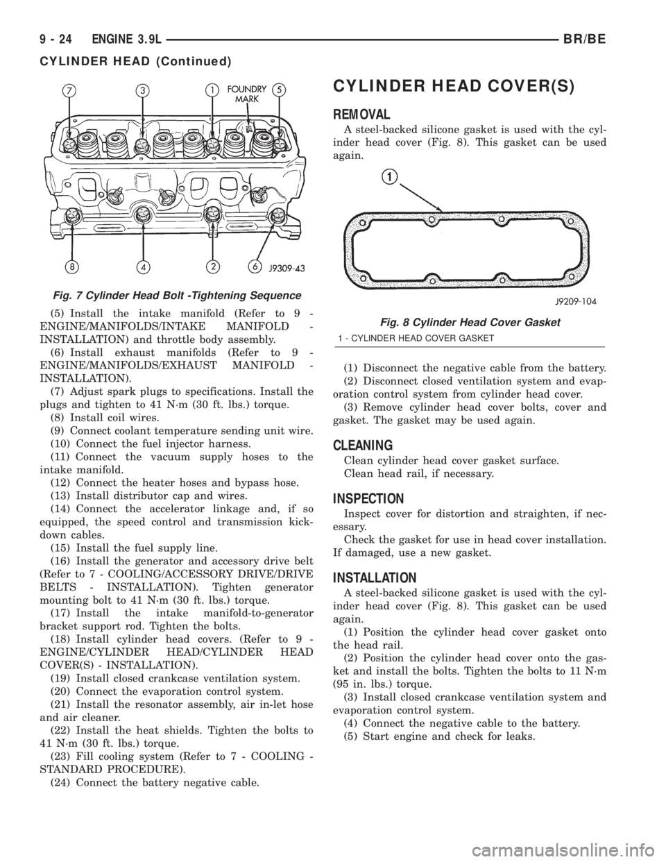
(3) Starting at top center, tighten all cylinder head
bolts, in sequence, to 68 N´m (50 ft. lbs.) torque (Fig.
7). Repeat procedure, tighten all cylinder head bolts
to 143 N´m (105 ft. lbs.) torque. Repeat procedure to
confirm that all bolts are at 143 N´m (105 ft. lbs.)
torque.
CAUTION: When tightening the rocker arm bolts, be
sure the piston in that cylinder is NOT at TDC. Con-
tact between the valves and piston could occur.
(4) Install push rods and rocker arm assemblies in
their original positions. Tighten the bolts to 28 N´m
(21 ft. lbs.) torque.
BR/BEENGINE 3.9L 9 - 23
CYLINDER HEAD (Continued)
Page 1171 of 2889
(5) Install the intake manifold (Refer to 9 -
ENGINE/MANIFOLDS/INTAKE MANIFOLD -
INSTALLATION) and throttle body assembly.
(6) Install exhaust manifolds (Refer to 9 -
ENGINE/MANIFOLDS/EXHAUST MANIFOLD -
INSTALLATION).
(7) Adjust spark plugs to specifications. Install the
plugs and tighten to 41 N´m (30 ft. lbs.) torque.
(8) Install coil wires.
(9) Connect coolant temperature sending unit wire.
(10) Connect the fuel injector harness.
(11) Connect the vacuum supply hoses to the
intake manifold.
(12) Connect the heater hoses and bypass hose.
(13) Install distributor cap and wires.
(14) Connect the accelerator linkage and, if so
equipped, the speed control and transmission kick-
down cables.
(15) Install the fuel supply line.
(16) Install the generator and accessory drive belt
(Refer to 7 - COOLING/ACCESSORY DRIVE/DRIVE
BELTS - INSTALLATION). Tighten generator
mounting bolt to 41 N´m (30 ft. lbs.) torque.
(17) Install the intake manifold-to-generator
bracket support rod. Tighten the bolts.
(18) Install cylinder head covers. (Refer to 9 -
ENGINE/CYLINDER HEAD/CYLINDER HEAD
COVER(S) - INSTALLATION).
(19) Install closed crankcase ventilation system.
(20) Connect the evaporation control system.
(21) Install the resonator assembly, air in-let hose
and air cleaner.
(22) Install the heat shields. Tighten the bolts to
41 N´m (30 ft. lbs.) torque.
(23) Fill cooling system (Refer to 7 - COOLING -
STANDARD PROCEDURE).
(24) Connect the battery negative cable.
CYLINDER HEAD COVER(S)
REMOVAL
A steel-backed silicone gasket is used with the cyl-
inder head cover (Fig. 8). This gasket can be used
again.
(1) Disconnect the negative cable from the battery.
(2) Disconnect closed ventilation system and evap-
oration control system from cylinder head cover.
(3) Remove cylinder head cover bolts, cover and
gasket. The gasket may be used again.
CLEANING
Clean cylinder head cover gasket surface.
Clean head rail, if necessary.
INSPECTION
Inspect cover for distortion and straighten, if nec-
essary.
Check the gasket for use in head cover installation.
If damaged, use a new gasket.
INSTALLATION
A steel-backed silicone gasket is used with the cyl-
inder head cover (Fig. 8). This gasket can be used
again.
(1) Position the cylinder head cover gasket onto
the head rail.
(2) Position the cylinder head cover onto the gas-
ket and install the bolts. Tighten the bolts to 11 N´m
(95 in. lbs.) torque.
(3) Install closed crankcase ventilation system and
evaporation control system.
(4) Connect the negative cable to the battery.
(5) Start engine and check for leaks.
Fig. 7 Cylinder Head Bolt -Tightening Sequence
Fig. 8 Cylinder Head Cover Gasket
1 - CYLINDER HEAD COVER GASKET
9 - 24 ENGINE 3.9LBR/BE
CYLINDER HEAD (Continued)
Page 1176 of 2889
Bearing Mount Adhesive. Plug should be 54.0 to 57.7
mm (2-1/8 to 2-5/16 in.) from bottom of the block.
CAMSHAFT & BEARINGS (IN
BLOCK)
REMOVALÐCAMSHAFT BEARINGS
(1) With engine completely disassembled, drive out
rear cam bearing core hole plug.
(2) Install proper size adapters and horseshoe
washers (part of Camshaft Bearing Remover/Installer
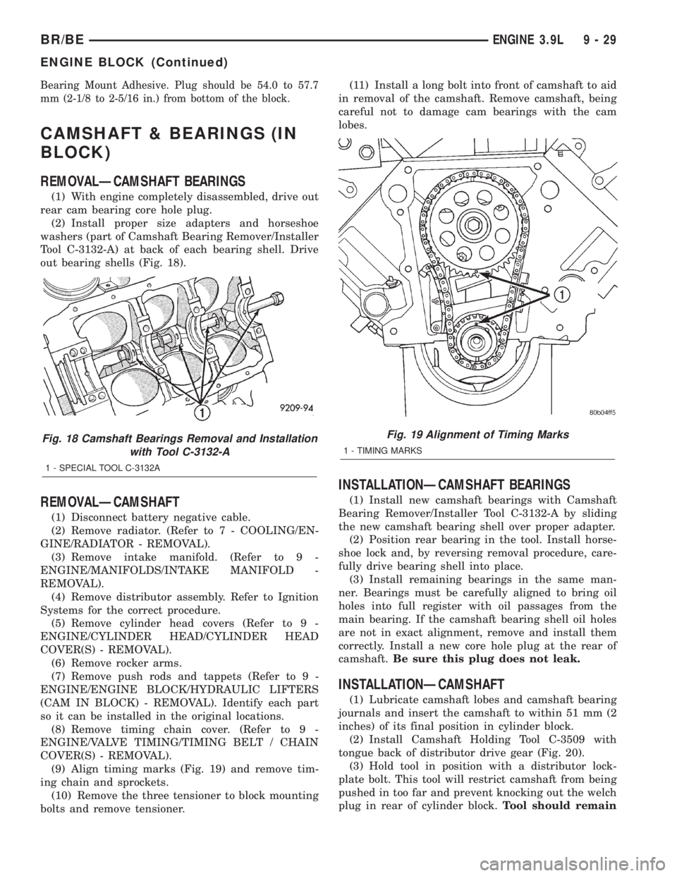
Tool C-3132-A) at back of each bearing shell. Drive
out bearing shells (Fig. 18).
REMOVALÐCAMSHAFT
(1) Disconnect battery negative cable.
(2) Remove radiator. (Refer to 7 - COOLING/EN-
GINE/RADIATOR - REMOVAL).
(3) Remove intake manifold. (Refer to 9 -
ENGINE/MANIFOLDS/INTAKE MANIFOLD -
REMOVAL).
(4) Remove distributor assembly. Refer to Ignition
Systems for the correct procedure.
(5) Remove cylinder head covers (Refer to 9 -
ENGINE/CYLINDER HEAD/CYLINDER HEAD
COVER(S) - REMOVAL).
(6) Remove rocker arms.
(7) Remove push rods and tappets (Refer to 9 -
ENGINE/ENGINE BLOCK/HYDRAULIC LIFTERS
(CAM IN BLOCK) - REMOVAL). Identify each part
so it can be installed in the original locations.
(8) Remove timing chain cover. (Refer to 9 -
ENGINE/VALVE TIMING/TIMING BELT / CHAIN
COVER(S) - REMOVAL).
(9) Align timing marks (Fig. 19) and remove tim-
ing chain and sprockets.
(10) Remove the three tensioner to block mounting
bolts and remove tensioner.(11) Install a long bolt into front of camshaft to aid
in removal of the camshaft. Remove camshaft, being
careful not to damage cam bearings with the cam
lobes.
INSTALLATIONÐCAMSHAFT BEARINGS
(1) Install new camshaft bearings with Camshaft
Bearing Remover/Installer Tool C-3132-A by sliding
the new camshaft bearing shell over proper adapter.
(2) Position rear bearing in the tool. Install horse-
shoe lock and, by reversing removal procedure, care-
fully drive bearing shell into place.
(3) Install remaining bearings in the same man-
ner. Bearings must be carefully aligned to bring oil
holes into full register with oil passages from the
main bearing. If the camshaft bearing shell oil holes
are not in exact alignment, remove and install them
correctly. Install a new core hole plug at the rear of
camshaft.Be sure this plug does not leak.
INSTALLATIONÐCAMSHAFT
(1) Lubricate camshaft lobes and camshaft bearing
journals and insert the camshaft to within 51 mm (2
inches) of its final position in cylinder block.
(2) Install Camshaft Holding Tool C-3509 with
tongue back of distributor drive gear (Fig. 20).
(3) Hold tool in position with a distributor lock-
plate bolt. This tool will restrict camshaft from being
pushed in too far and prevent knocking out the welch
plug in rear of cylinder block.Tool should remain
Fig. 18 Camshaft Bearings Removal and Installation
with Tool C-3132-A
1 - SPECIAL TOOL C-3132A
Fig. 19 Alignment of Timing Marks
1 - TIMING MARKS
BR/BEENGINE 3.9L 9 - 29
ENGINE BLOCK (Continued)
Page 1178 of 2889
(8) Turn crankshaft and camshaft to line up with
keyway location in crankshaft sprocket and in cam-
shaft sprocket.
(9) Lift sprockets and chain (keep sprockets tight
against the chain in position as described).
(10) Slide both sprockets evenly over their respec-
tive shafts and use a straightedge to check alignment
of timing marks (Fig. 22).
(11) Install the camshaft bolt/cup washer. Tighten
bolt to 68 N´m (50 ft. lbs.) torque.
(12) Measure camshaft end play (Fig. 23). (Refer to
9 - ENGINE - SPECIFICATIONS) for proper clear-
ance. If not within limits, install a new timing chain
tensioner.
(13) Each tappet reused must be installed in the
same position at which it was removed.When cam-
shaft is replaced, all of the tappets must be
replaced.Install hydraulic tappets (Refer to 9 -
ENGINE/ENGINE BLOCK/HYDRAULIC LIFTERS
(CAM IN BLOCK) - INSTALLATION).
(14) Install timing chain cover (Refer to 9 -
ENGINE/VALVE TIMING/TIMING BELT / CHAIN
COVER(S) - INSTALLATION).
(15) Install intake manifold (Refer to 9 - ENGINE/
MANIFOLDS/INTAKE MANIFOLD - INSTALLA-
TION).
(16) Install distributor.
(17) Install cylinder head covers (Refer to 9 -
ENGINE/CYLINDER HEAD/CYLINDER HEAD
COVER(S) - INSTALLATION).
(18) Install radiator (Refer to 7 - COOLING/EN-
GINE/RADIATOR - INSTALLATION).
(19) Fill cooling system (Refer to 7 - COOLING -
STANDARD PROCEDURE).
(20) Connect battery negative cable.
(21) Start engine and check for leaks.
CONNECTING ROD BEARINGS
STANDARD PROCEDURE-CONNECTING ROD
BEARING FITTING
Fit all rods on a bank until completed. DO NOT
alternate from one bank to another, because connect-
ing rods and pistons are not interchangeable from
one bank to another.
The bearing caps are not interchangeable and
should be marked at removal to ensure correct
assembly.
Each bearing cap has a small V-groove across the
parting face. When installing the lower bearing shell,
be certain that the V-groove in the shell is in line
with the V-groove in the cap. This provides lubrica-
tion of the cylinder wall in the opposite bank.The bearing shells must be installed so that the
tangs are in the machined grooves in the rods and
caps.
Limits of taper or out-of-round on any crankshaft
journals should be held to 0.025 mm (0.001 in.).
Bearings are available in 0.025 mm (0.001 in.), 0.051
mm (0.002 in.), 0.076 mm (0.003 in.), 0.254 mm
(0.010 in.) and 0.305 mm (0.012 in.) undersize.
Install the bearings in pairs. DO NOT use a new
bearing half with an old bearing half. DO NOT
file the rods or bearing caps.
CRANKSHAFT
DESCRIPTION
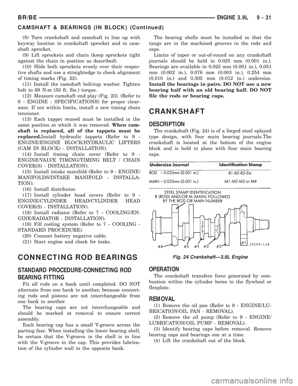
The crankshaft (Fig. 24) is of a forged steel splayed
type design, with four main bearing journals.The
crankshaft is located at the bottom of the engine
block and is held in place with four main bearing
caps.
OPERATION
The crankshaft transfers force generated by com-
bustion within the cylinder bores to the flywheel or
flexplate.
REMOVAL
(1) Remove the oil pan (Refer to 9 - ENGINE/LU-
BRICATION/OIL PAN - REMOVAL).
(2) Remove the oil pump (Refer to 9 - ENGINE/
LUBRICATION/OIL PUMP - REMOVAL).
(3) Identify bearing caps before removal. Remove
bearing caps and bearings one at a time.
(4) Lift the crankshaft out of the block.
Fig. 24 CrankshaftÐ3.9L Engine
BR/BEENGINE 3.9L 9 - 31
CAMSHAFT & BEARINGS (IN BLOCK) (Continued)
Page 1184 of 2889
LOWER SEAL
(1) Clean the rear main cap mating surfaces
including the oil pan gasket groove.
(2) Carefully install a new upper seal. Refer to
UPPER SEALÐCRANKSHAFT INSTALLED.
(3)
Lightly oil the new lower seal lips with engine oil.
(4) Install a new lower seal in bearing cap with
the white paint facing the rear of engine.
(5) Apply 5 mm (0.20 in.) drop of MopartGasket
Maker, or equivalent, on each side of the rear main
bearing cap (Fig. 33). DO NOT over-apply sealant or
allow the sealant to contact the rubber seal. Assem-
ble bearing cap to cylinder block immediately after
sealant application.
(6) To align the bearing cap, use cap slot, align-
ment dowel, and cap bolts. DO NOT remove excess
material after assembly. DO NOT strike rear cap
more than two times for proper engagement.
(7) Install the rear main bearing cap with cleaned
and oiled cap bolts. Alternately tighten the cap bolts
to 115 N´m (85 ft. lbs.) torque.
(8) Install oil pump (Refer to 9 - ENGINE/LUBRI-
CATION/OIL PUMP - INSTALLATION).
(9) Apply MopartGEN II Silicone Rubber Adhe-
sive Sealant, or equivalent, at bearing cap-to-block
joint to provide cap to block and oil pan sealing.
Apply enough sealant so that a small amount is
squeezed out. Withdraw nozzle and wipe excess seal-
ant off the oil pan seal groove.
(10)
Immediately install the oil pan (Refer to 9 -
ENGINE/LUBRICATION/OIL PAN - INSTALLATION).
DISTRIBUTOR BUSHING
REMOVAL
(1) Remove distributor.
(2) Remove the intake manifold (Refer to 9 -
ENGINE/MANIFOLDS/INTAKE MANIFOLD -
REMOVAL).
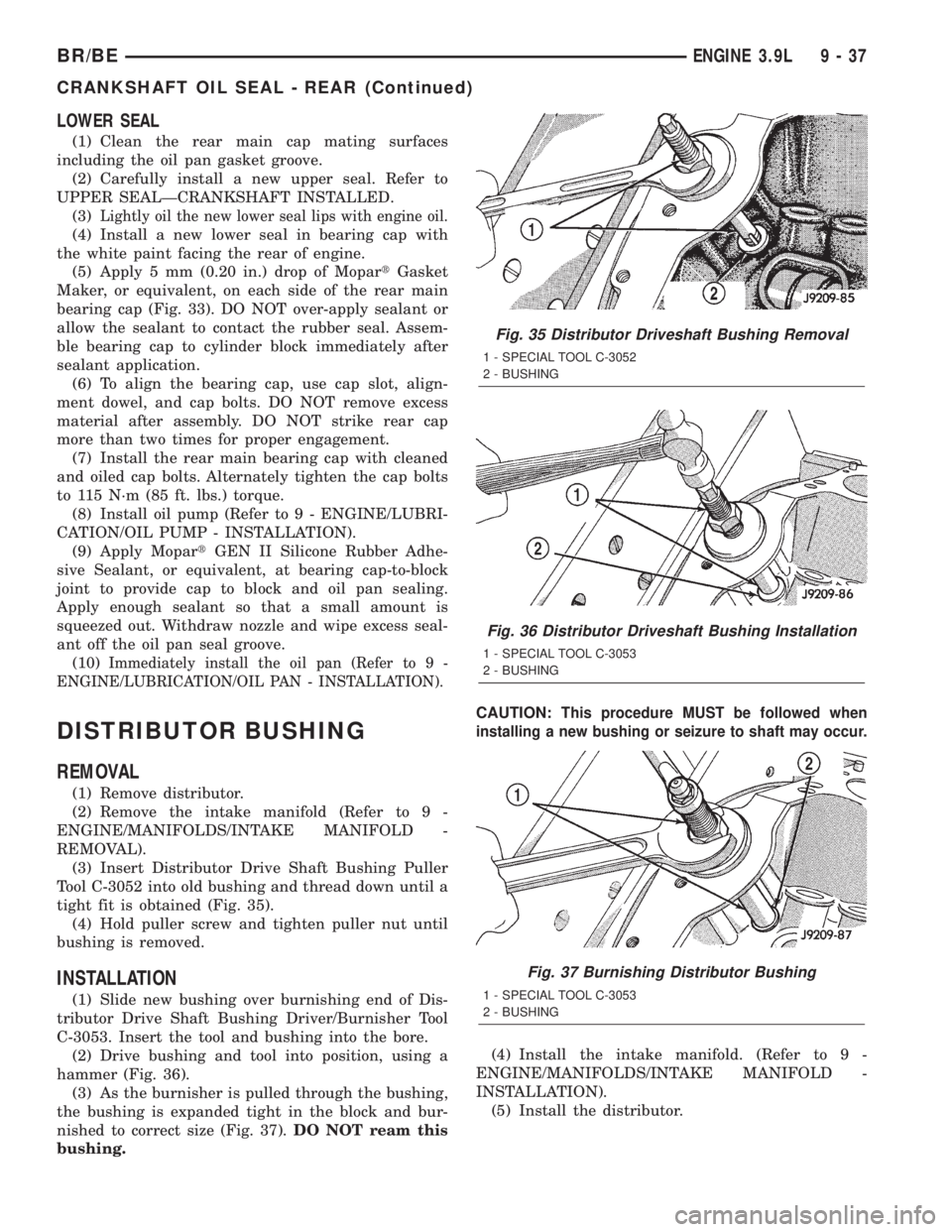
(3) Insert Distributor Drive Shaft Bushing Puller
Tool C-3052 into old bushing and thread down until a
tight fit is obtained (Fig. 35).
(4) Hold puller screw and tighten puller nut until
bushing is removed.
INSTALLATION
(1) Slide new bushing over burnishing end of Dis-
tributor Drive Shaft Bushing Driver/Burnisher Tool
C-3053. Insert the tool and bushing into the bore.
(2) Drive bushing and tool into position, using a
hammer (Fig. 36).
(3) As the burnisher is pulled through the bushing,
the bushing is expanded tight in the block and bur-
nished to correct size (Fig. 37).DO NOT ream this
bushing.CAUTION:
This procedure MUST be followed when
installing a new bushing or seizure to shaft may occur.
(4) Install the intake manifold. (Refer to 9 -
ENGINE/MANIFOLDS/INTAKE MANIFOLD -
INSTALLATION).
(5) Install the distributor.
Fig. 35 Distributor Driveshaft Bushing Removal
1 - SPECIAL TOOL C-3052
2 - BUSHING
Fig. 36 Distributor Driveshaft Bushing Installation
1 - SPECIAL TOOL C-3053
2 - BUSHING
Fig. 37 Burnishing Distributor Bushing
1 - SPECIAL TOOL C-3053
2 - BUSHING
BR/BEENGINE 3.9L 9 - 37
CRANKSHAFT OIL SEAL - REAR (Continued)
Page 1186 of 2889
20-110 seconds to leak-down. Discard tappets with
leak-down time interval not within this specification.
REMOVAL
(1) Remove the air cleaner assembly and air in-let
hose.
(2) Remove cylinder head cover (Refer to 9 -
ENGINE/CYLINDER HEAD/CYLINDER HEAD
COVER(S) - REMOVAL).
(3) Remove rocker assembly and push rods. Iden-
tify push rods to ensure installation in original loca-
tions.
(4) Remove intake manifold (Refer to 9 - ENGINE/
MANIFOLDS/INTAKE MANIFOLD - REMOVAL).(5) Remove yoke retainer and aligning yokes.
(6) Slide Hydraulic Tappet Remover/Installer Tool
C-4129-A through opening in cylinder head and seat
tool firmly in the head of tappet.
(7) Pull tappet out of bore with a twisting motion.
If all tappets are to be removed, identify tappets to
ensure installation in original location.
(8) If the tappet or bore in cylinder block is scored,
scuffed, or shows signs of sticking, ream the bore to
next oversize. Replace with oversize tappet.
CLEANING
Clean tappet with a suitable solvent. Rinse in hot
water and blow dry with a clean shop rag or com-
pressed air.
INSTALLATION
(1) Lubricate tappets.
(2) Install tappets and push rods in their original
positions. Ensure that the oil feed hole in the side of
the tappet body faces up (away from the crankshaft).
(3) Install aligning yokes with ARROW toward
camshaft.
(4) Install yoke retainer. Tighten the bolts to 23
N´m (200 in. lbs.) torque. Install intake manifold
(Refer to 9 - ENGINE/MANIFOLDS/INTAKE MANI-
FOLD - INSTALLATION).
(5) Install push rods in original positions.
(6) Install rocker arms.
(7) Install cylinder head cover (Refer to 9 -
ENGINE/CYLINDER HEAD/CYLINDER HEAD
COVER(S) - INSTALLATION).
(8) Install air cleaner assembly and air in-let hose.
(9) Start and operate engine. Warm up to normal
operating temperature.
CAUTION: To prevent damage to valve mechanism,
engine must not be run above fast idle until all
hydraulic tappets have filled with oil and have
become quiet.
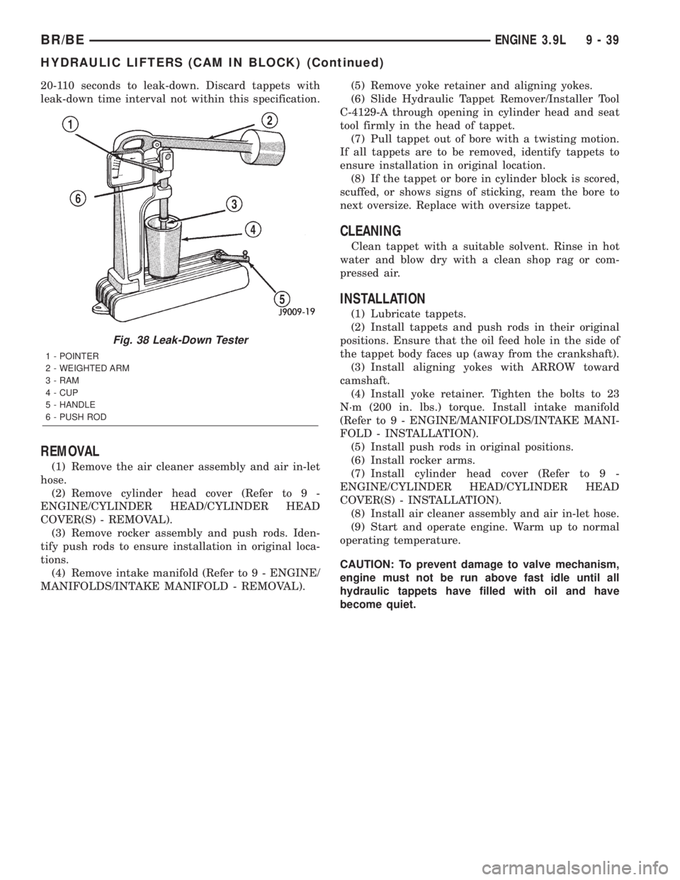
Fig. 38 Leak-Down Tester
1 - POINTER
2 - WEIGHTED ARM
3 - RAM
4 - CUP
5 - HANDLE
6 - PUSH ROD
BR/BEENGINE 3.9L 9 - 39
HYDRAULIC LIFTERS (CAM IN BLOCK) (Continued)