2001 DODGE RAM transmission oil
[x] Cancel search: transmission oilPage 2181 of 2889
PROCEDURE ONE
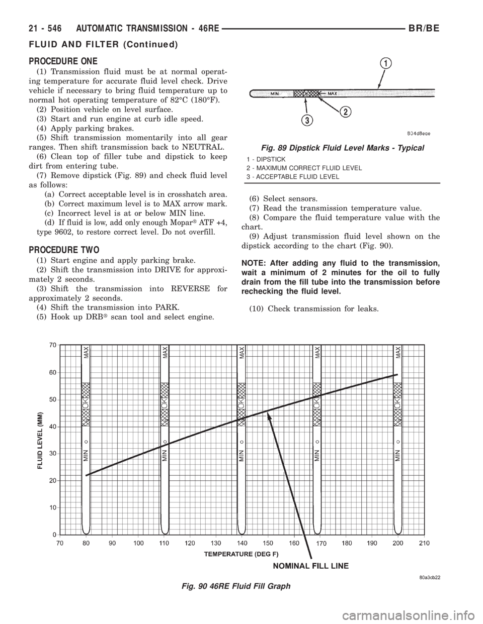
(1) Transmission fluid must be at normal operat-
ing temperature for accurate fluid level check. Drive
vehicle if necessary to bring fluid temperature up to
normal hot operating temperature of 82ÉC (180ÉF).
(2) Position vehicle on level surface.
(3) Start and run engine at curb idle speed.
(4) Apply parking brakes.
(5) Shift transmission momentarily into all gear
ranges. Then shift transmission back to NEUTRAL.
(6) Clean top of filler tube and dipstick to keep
dirt from entering tube.
(7) Remove dipstick (Fig. 89) and check fluid level
as follows:
(a) Correct acceptable level is in crosshatch area.
(b)
Correct maximum level is to MAX arrow mark.
(c) Incorrect level is at or below MIN line.
(d)
If fluid is low, add only enough MopartATF +4,
type 9602, to restore correct level. Do not overfill.
PROCEDURE TWO
(1) Start engine and apply parking brake.
(2) Shift the transmission into DRIVE for approxi-
mately 2 seconds.
(3) Shift the transmission into REVERSE for
approximately 2 seconds.
(4) Shift the transmission into PARK.
(5) Hook up DRBtscan tool and select engine.(6) Select sensors.
(7) Read the transmission temperature value.
(8) Compare the fluid temperature value with the
chart.
(9) Adjust transmission fluid level shown on the
dipstick according to the chart (Fig. 90).
NOTE: After adding any fluid to the transmission,
wait a minimum of 2 minutes for the oil to fully
drain from the fill tube into the transmission before
rechecking the fluid level.
(10) Check transmission for leaks.
Fig. 89 Dipstick Fluid Level Marks - Typical
1 - DIPSTICK
2 - MAXIMUM CORRECT FLUID LEVEL
3 - ACCEPTABLE FLUID LEVEL
Fig. 90 46RE Fluid Fill Graph
21 - 546 AUTOMATIC TRANSMISSION - 46REBR/BE
FLUID AND FILTER (Continued)
Page 2182 of 2889
STANDARD PROCEDURE - FLUID AND FILTER
REPLACEMENT
For proper service intervals (Refer to LUBRICA-
TION & MAINTENANCE/MAINTENANCE SCHED-
ULES - DESCRIPTION). The service fluid fill after a
filter change is approximately 3.8 liters (4.0 quarts).
(1) Hoist and support vehicle on safety stands.
(2) Place a large diameter shallow drain pan
beneath the transmission pan.
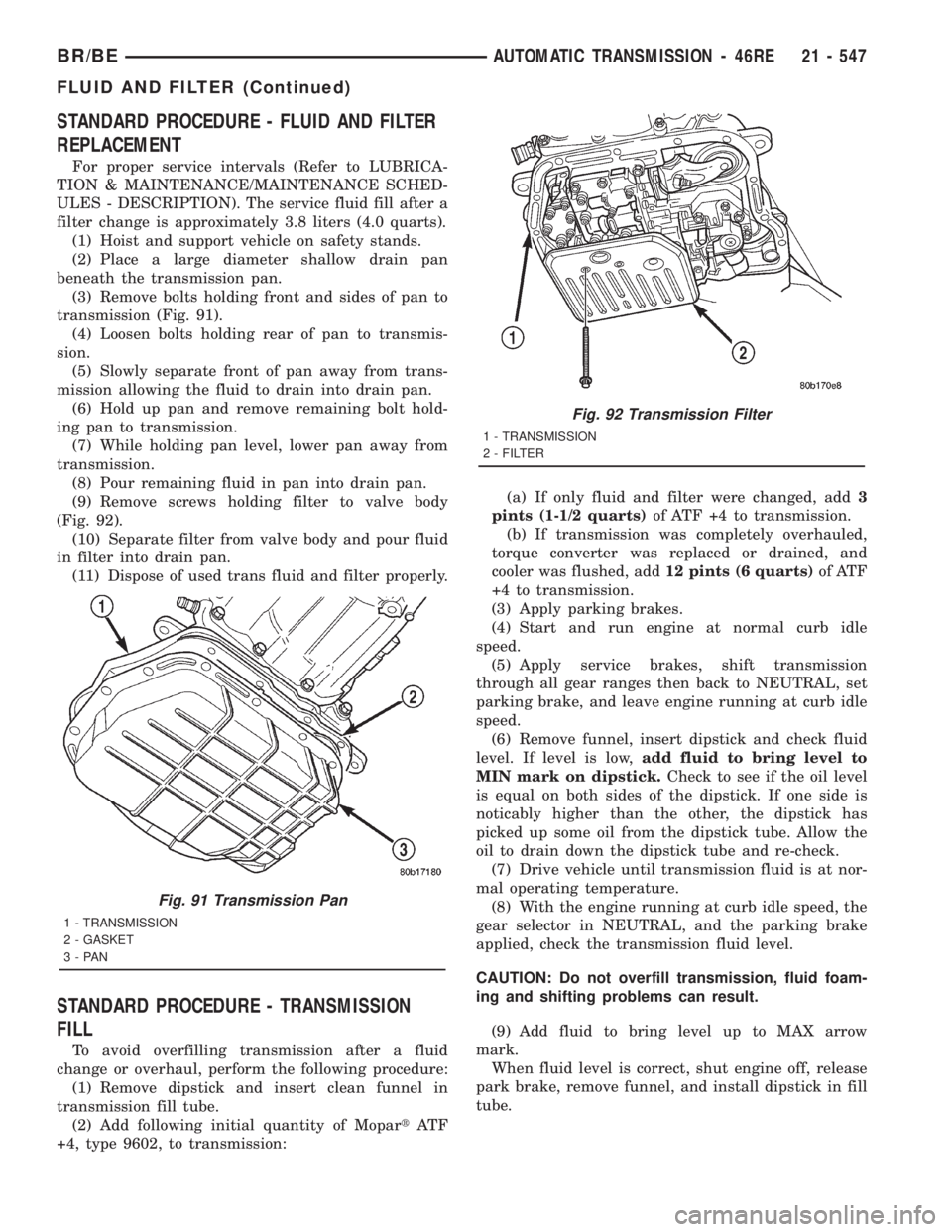
(3) Remove bolts holding front and sides of pan to
transmission (Fig. 91).
(4) Loosen bolts holding rear of pan to transmis-
sion.
(5) Slowly separate front of pan away from trans-
mission allowing the fluid to drain into drain pan.
(6) Hold up pan and remove remaining bolt hold-
ing pan to transmission.
(7) While holding pan level, lower pan away from
transmission.
(8) Pour remaining fluid in pan into drain pan.
(9) Remove screws holding filter to valve body
(Fig. 92).
(10) Separate filter from valve body and pour fluid
in filter into drain pan.
(11) Dispose of used trans fluid and filter properly.
STANDARD PROCEDURE - TRANSMISSION
FILL
To avoid overfilling transmission after a fluid
change or overhaul, perform the following procedure:
(1) Remove dipstick and insert clean funnel in
transmission fill tube.
(2) Add following initial quantity of MopartAT F
+4, type 9602, to transmission:(a) If only fluid and filter were changed, add3
pints (1-1/2 quarts)of ATF +4 to transmission.
(b) If transmission was completely overhauled,
torque converter was replaced or drained, and
cooler was flushed, add12 pints (6 quarts)of ATF
+4 to transmission.
(3) Apply parking brakes.
(4) Start and run engine at normal curb idle
speed.
(5) Apply service brakes, shift transmission
through all gear ranges then back to NEUTRAL, set
parking brake, and leave engine running at curb idle
speed.
(6) Remove funnel, insert dipstick and check fluid
level. If level is low,add fluid to bring level to
MIN mark on dipstick.Check to see if the oil level
is equal on both sides of the dipstick. If one side is
noticably higher than the other, the dipstick has
picked up some oil from the dipstick tube. Allow the
oil to drain down the dipstick tube and re-check.
(7) Drive vehicle until transmission fluid is at nor-
mal operating temperature.
(8) With the engine running at curb idle speed, the
gear selector in NEUTRAL, and the parking brake
applied, check the transmission fluid level.
CAUTION: Do not overfill transmission, fluid foam-
ing and shifting problems can result.
(9) Add fluid to bring level up to MAX arrow
mark.
When fluid level is correct, shut engine off, release
park brake, remove funnel, and install dipstick in fill
tube.
Fig. 91 Transmission Pan
1 - TRANSMISSION
2 - GASKET
3-PAN
Fig. 92 Transmission Filter
1 - TRANSMISSION
2 - FILTER
BR/BEAUTOMATIC TRANSMISSION - 46RE 21 - 547
FLUID AND FILTER (Continued)
Page 2183 of 2889
FRONT CLUTCH
DESCRIPTION
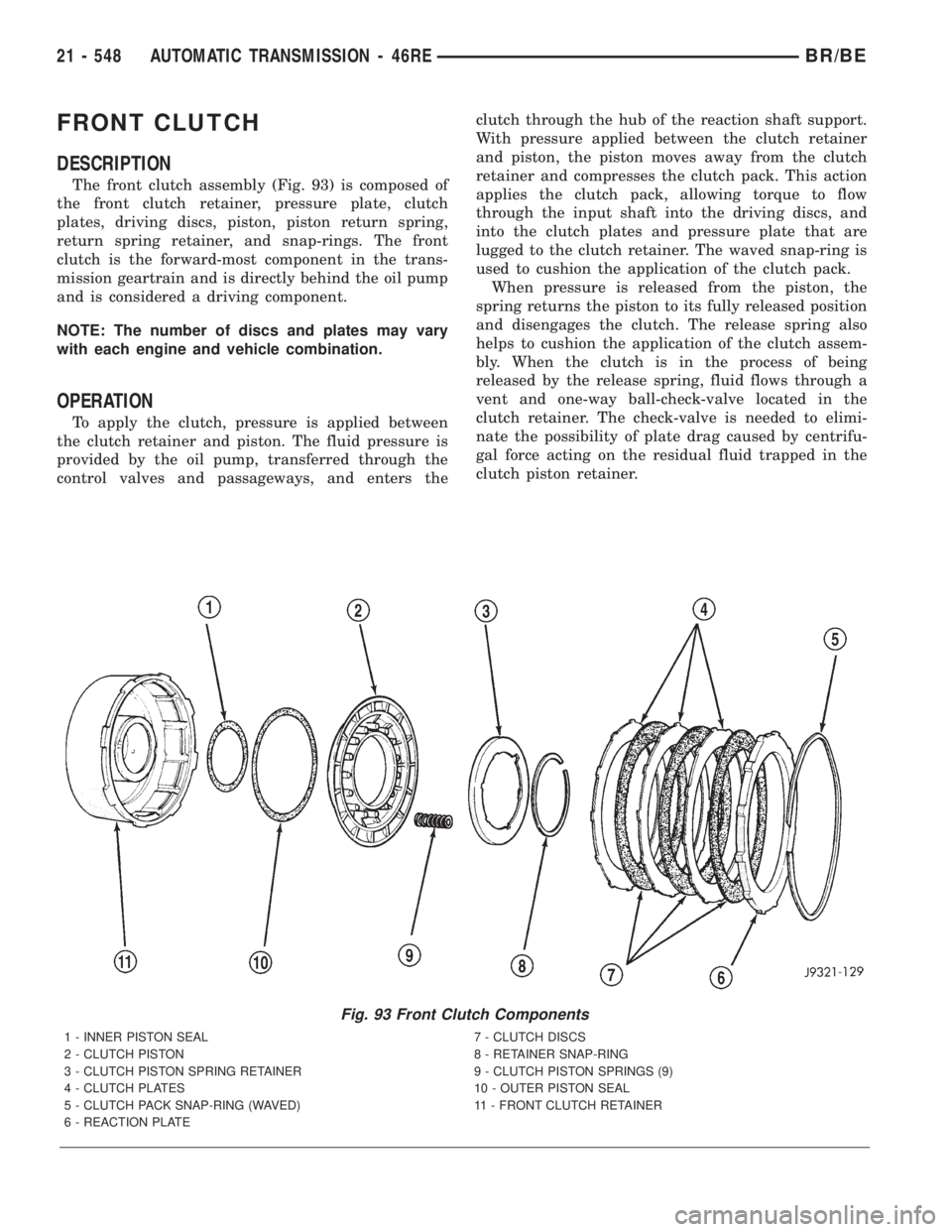
The front clutch assembly (Fig. 93) is composed of
the front clutch retainer, pressure plate, clutch
plates, driving discs, piston, piston return spring,
return spring retainer, and snap-rings. The front
clutch is the forward-most component in the trans-
mission geartrain and is directly behind the oil pump
and is considered a driving component.
NOTE: The number of discs and plates may vary
with each engine and vehicle combination.
OPERATION
To apply the clutch, pressure is applied between
the clutch retainer and piston. The fluid pressure is
provided by the oil pump, transferred through the
control valves and passageways, and enters theclutch through the hub of the reaction shaft support.
With pressure applied between the clutch retainer
and piston, the piston moves away from the clutch
retainer and compresses the clutch pack. This action
applies the clutch pack, allowing torque to flow
through the input shaft into the driving discs, and
into the clutch plates and pressure plate that are
lugged to the clutch retainer. The waved snap-ring is
used to cushion the application of the clutch pack.
When pressure is released from the piston, the
spring returns the piston to its fully released position
and disengages the clutch. The release spring also
helps to cushion the application of the clutch assem-
bly. When the clutch is in the process of being
released by the release spring, fluid flows through a
vent and one-way ball-check-valve located in the
clutch retainer. The check-valve is needed to elimi-
nate the possibility of plate drag caused by centrifu-
gal force acting on the residual fluid trapped in the
clutch piston retainer.
Fig. 93 Front Clutch Components
1 - INNER PISTON SEAL 7 - CLUTCH DISCS
2 - CLUTCH PISTON 8 - RETAINER SNAP-RING
3 - CLUTCH PISTON SPRING RETAINER 9 - CLUTCH PISTON SPRINGS (9)
4 - CLUTCH PLATES 10 - OUTER PISTON SEAL
5 - CLUTCH PACK SNAP-RING (WAVED) 11 - FRONT CLUTCH RETAINER
6 - REACTION PLATE
21 - 548 AUTOMATIC TRANSMISSION - 46REBR/BE
Page 2187 of 2889
OPERATION
The application of the piston is accomplished by
applying pressure between the two lands of the pis-
ton. The pressure acts against the larger lower land
to push the piston downward, allowing the piston rod
to extend though its guide against the apply lever.
Release of the servo at the 2-3 upshift is accom-
plished by a combination of spring and line pressure,
acting on the bottom of the larger land of the piston.
The small piston is used to cushion the application of
the band by bleeding oil through a small orifice in
the larger piston. The release timing of the kickdown
servo is very important to obtain a smooth but firm
shift. The release has to be very quick, just as the
front clutch application is taking place. Otherwise,
engine runaway or a shift hesitation will occur. To
accomplish this, the band retains its holding capacity
until the front clutch is applied, giving a small
amount of overlap between them.
DISASSEMBLY
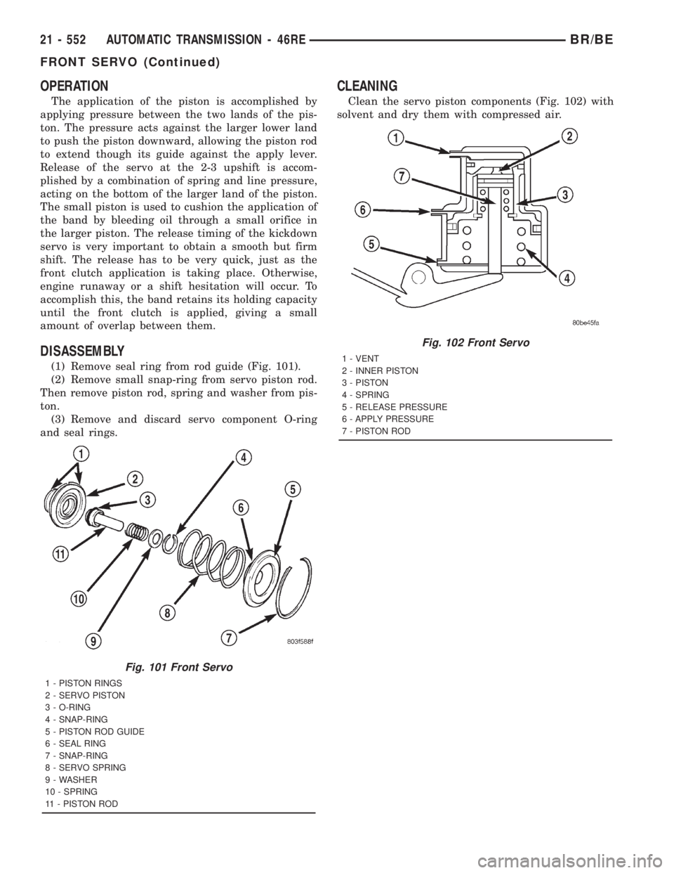
(1) Remove seal ring from rod guide (Fig. 101).
(2) Remove small snap-ring from servo piston rod.
Then remove piston rod, spring and washer from pis-
ton.
(3) Remove and discard servo component O-ring
and seal rings.
CLEANING
Clean the servo piston components (Fig. 102) with
solvent and dry them with compressed air.
Fig. 101 Front Servo
1 - PISTON RINGS
2 - SERVO PISTON
3 - O-RING
4 - SNAP-RING
5 - PISTON ROD GUIDE
6 - SEAL RING
7 - SNAP-RING
8 - SERVO SPRING
9 - WASHER
10 - SPRING
11 - PISTON ROD
Fig. 102 Front Servo
1 - VENT
2 - INNER PISTON
3 - PISTON
4 - SPRING
5 - RELEASE PRESSURE
6 - APPLY PRESSURE
7 - PISTON ROD
21 - 552 AUTOMATIC TRANSMISSION - 46REBR/BE
FRONT SERVO (Continued)
Page 2189 of 2889
OIL PUMP
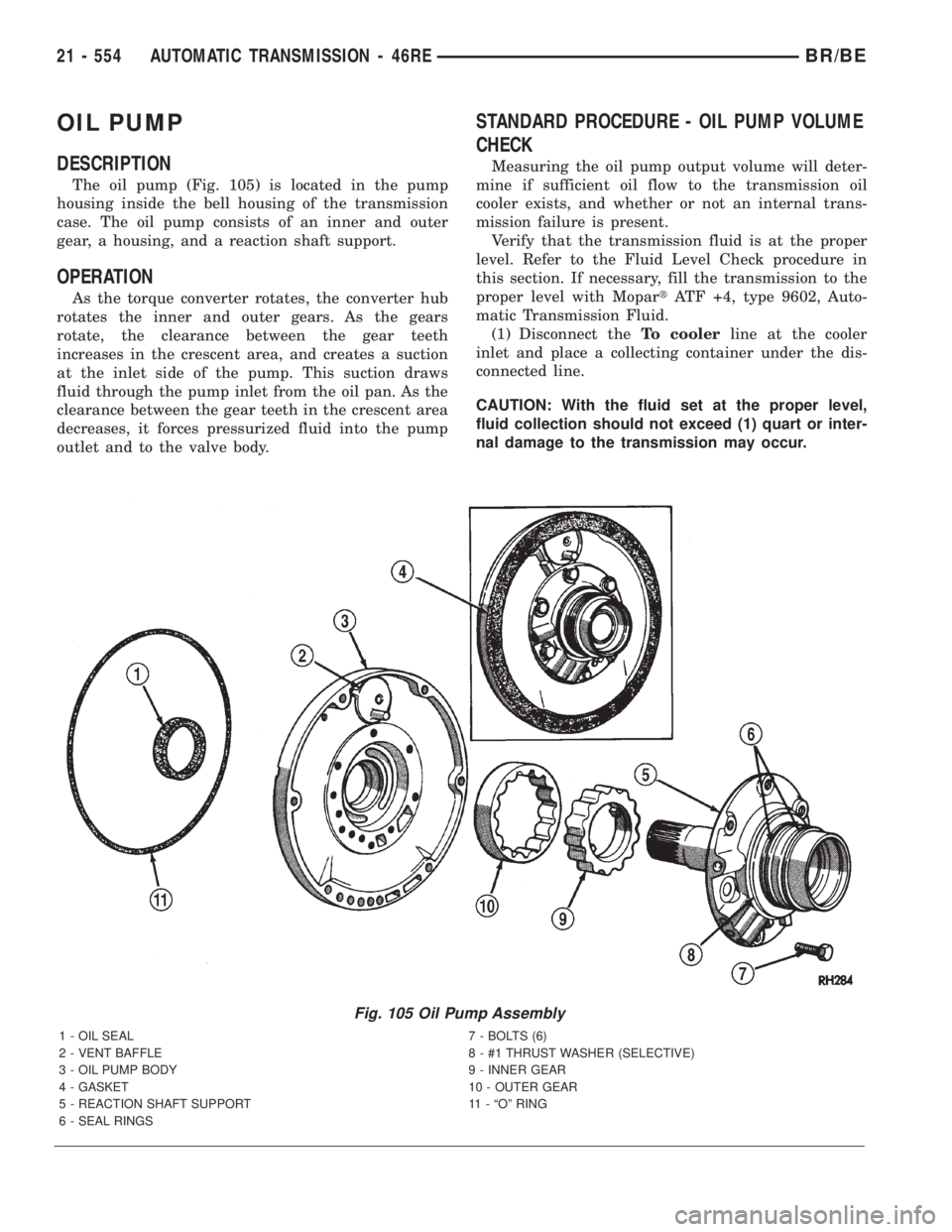
DESCRIPTION
The oil pump (Fig. 105) is located in the pump
housing inside the bell housing of the transmission
case. The oil pump consists of an inner and outer
gear, a housing, and a reaction shaft support.
OPERATION
As the torque converter rotates, the converter hub
rotates the inner and outer gears. As the gears
rotate, the clearance between the gear teeth
increases in the crescent area, and creates a suction
at the inlet side of the pump. This suction draws
fluid through the pump inlet from the oil pan. As the
clearance between the gear teeth in the crescent area
decreases, it forces pressurized fluid into the pump
outlet and to the valve body.
STANDARD PROCEDURE - OIL PUMP VOLUME
CHECK
Measuring the oil pump output volume will deter-
mine if sufficient oil flow to the transmission oil
cooler exists, and whether or not an internal trans-
mission failure is present.
Verify that the transmission fluid is at the proper
level. Refer to the Fluid Level Check procedure in
this section. If necessary, fill the transmission to the
proper level with MopartATF +4, type 9602, Auto-
matic Transmission Fluid.
(1) Disconnect theTo coolerline at the cooler
inlet and place a collecting container under the dis-
connected line.
CAUTION: With the fluid set at the proper level,
fluid collection should not exceed (1) quart or inter-
nal damage to the transmission may occur.
Fig. 105 Oil Pump Assembly
1 - OIL SEAL 7 - BOLTS (6)
2 - VENT BAFFLE 8 - #1 THRUST WASHER (SELECTIVE)
3 - OIL PUMP BODY 9 - INNER GEAR
4 - GASKET 10 - OUTER GEAR
5 - REACTION SHAFT SUPPORT 11 - ªOº RING
6 - SEAL RINGS
21 - 554 AUTOMATIC TRANSMISSION - 46REBR/BE
Page 2190 of 2889
(2) Run the engineat curb idle speed, with the
shift selector in neutral.
(3) If one quart of transmission fluid is collected in
the container in 20 seconds or less, oil pump flow vol-
ume is within acceptable limits. If fluid flow is inter-
mittent, or it takes more than 20 seconds to collect
one quart of fluid, refer to the Hydraulic Pressure
tests in this section for further diagnosis.
(4) Re-connect theTo coolerline to the transmis-
sion cooler inlet.
(5) Refill the transmission to proper level.
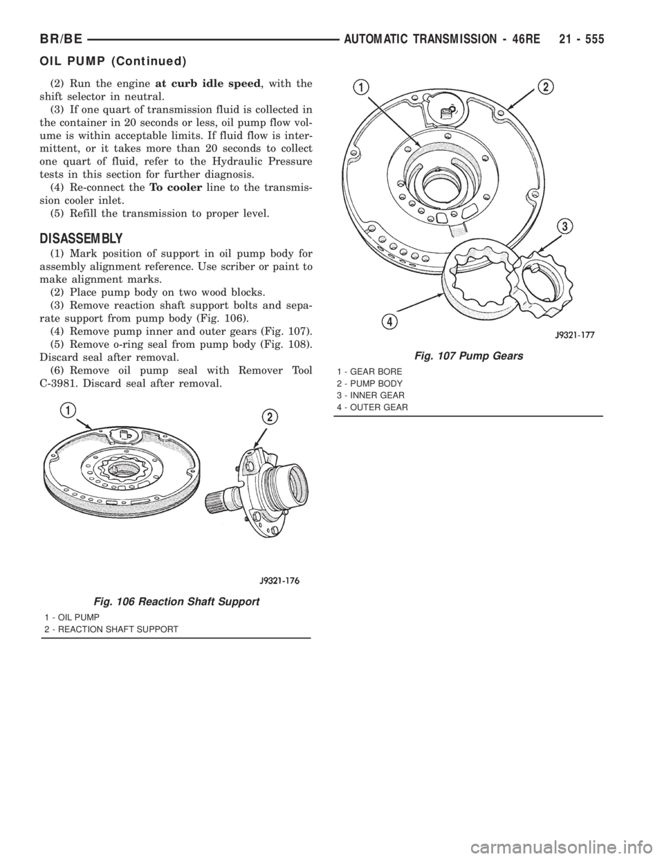
DISASSEMBLY
(1) Mark position of support in oil pump body for
assembly alignment reference. Use scriber or paint to
make alignment marks.
(2) Place pump body on two wood blocks.
(3) Remove reaction shaft support bolts and sepa-
rate support from pump body (Fig. 106).
(4) Remove pump inner and outer gears (Fig. 107).
(5) Remove o-ring seal from pump body (Fig. 108).
Discard seal after removal.
(6) Remove oil pump seal with Remover Tool
C-3981. Discard seal after removal.
Fig. 106 Reaction Shaft Support
1 - OIL PUMP
2 - REACTION SHAFT SUPPORT
Fig. 107 Pump Gears
1 - GEAR BORE
2 - PUMP BODY
3 - INNER GEAR
4 - OUTER GEAR
BR/BEAUTOMATIC TRANSMISSION - 46RE 21 - 555
OIL PUMP (Continued)
Page 2191 of 2889
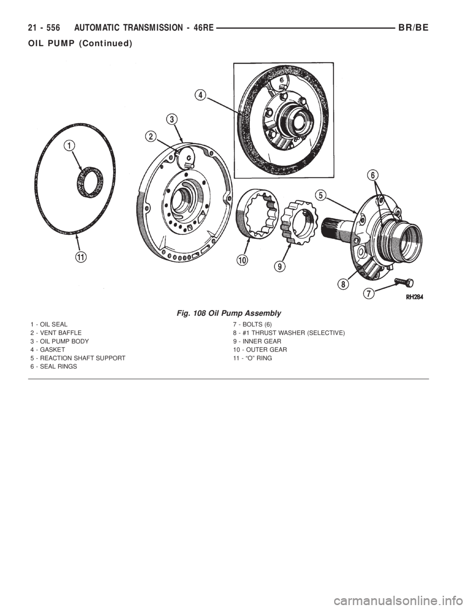
Fig. 108 Oil Pump Assembly
1 - OIL SEAL 7 - BOLTS (6)
2 - VENT BAFFLE 8 - #1 THRUST WASHER (SELECTIVE)
3 - OIL PUMP BODY 9 - INNER GEAR
4 - GASKET 10 - OUTER GEAR
5 - REACTION SHAFT SUPPORT 11 - ªOº RING
6 - SEAL RINGS
21 - 556 AUTOMATIC TRANSMISSION - 46REBR/BE
OIL PUMP (Continued)
Page 2192 of 2889
OIL PUMP BUSHING REMOVAL
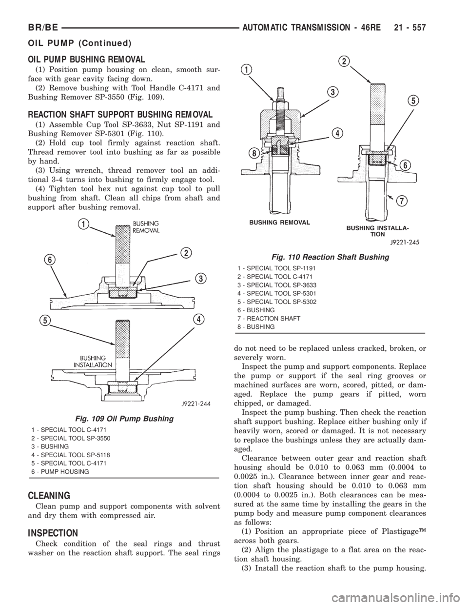
(1) Position pump housing on clean, smooth sur-
face with gear cavity facing down.
(2) Remove bushing with Tool Handle C-4171 and
Bushing Remover SP-3550 (Fig. 109).
REACTION SHAFT SUPPORT BUSHING REMOVAL
(1) Assemble Cup Tool SP-3633, Nut SP-1191 and
Bushing Remover SP-5301 (Fig. 110).
(2) Hold cup tool firmly against reaction shaft.
Thread remover tool into bushing as far as possible
by hand.
(3) Using wrench, thread remover tool an addi-
tional 3-4 turns into bushing to firmly engage tool.
(4) Tighten tool hex nut against cup tool to pull
bushing from shaft. Clean all chips from shaft and
support after bushing removal.
CLEANING
Clean pump and support components with solvent
and dry them with compressed air.
INSPECTION
Check condition of the seal rings and thrust
washer on the reaction shaft support. The seal ringsdo not need to be replaced unless cracked, broken, or
severely worn.
Inspect the pump and support components. Replace
the pump or support if the seal ring grooves or
machined surfaces are worn, scored, pitted, or dam-
aged. Replace the pump gears if pitted, worn
chipped, or damaged.
Inspect the pump bushing. Then check the reaction
shaft support bushing. Replace either bushing only if
heavily worn, scored or damaged. It is not necessary
to replace the bushings unless they are actually dam-
aged.
Clearance between outer gear and reaction shaft
housing should be 0.010 to 0.063 mm (0.0004 to
0.0025 in.). Clearance between inner gear and reac-
tion shaft housing should be 0.010 to 0.063 mm
(0.0004 to 0.0025 in.). Both clearances can be mea-
sured at the same time by installing the gears in the
pump body and measure pump component clearances
as follows:
(1) Position an appropriate piece of PlastigageŸ
across both gears.
(2) Align the plastigage to a flat area on the reac-
tion shaft housing.
(3) Install the reaction shaft to the pump housing.
Fig. 109 Oil Pump Bushing
1 - SPECIAL TOOL C-4171
2 - SPECIAL TOOL SP-3550
3 - BUSHING
4 - SPECIAL TOOL SP-5118
5 - SPECIAL TOOL C-4171
6 - PUMP HOUSING
Fig. 110 Reaction Shaft Bushing
1 - SPECIAL TOOL SP-1191
2 - SPECIAL TOOL C-4171
3 - SPECIAL TOOL SP-3633
4 - SPECIAL TOOL SP-5301
5 - SPECIAL TOOL SP-5302
6 - BUSHING
7 - REACTION SHAFT
8 - BUSHING
BR/BEAUTOMATIC TRANSMISSION - 46RE 21 - 557
OIL PUMP (Continued)