2001 DODGE RAM brake
[x] Cancel search: brakePage 1517 of 2889
(11) Inspect accelerator cable, transmission throt-
tle cable (if equipped) and cruise control cable con-
nections (if equipped). Check their connections to the
throttle arm of throttle body for any binding or
restrictions.
(12) If equipped with vacuum brake booster, verify
that vacuum booster hose is firmly connected to fit-
ting on intake manifold. Also check connection to
brake vacuum booster.
(13) Inspect the air cleaner inlet and air cleaner
element for dirt or restrictions.
(14) Inspect radiator grille area, radiator fins and
air conditioning condenser for restrictions.
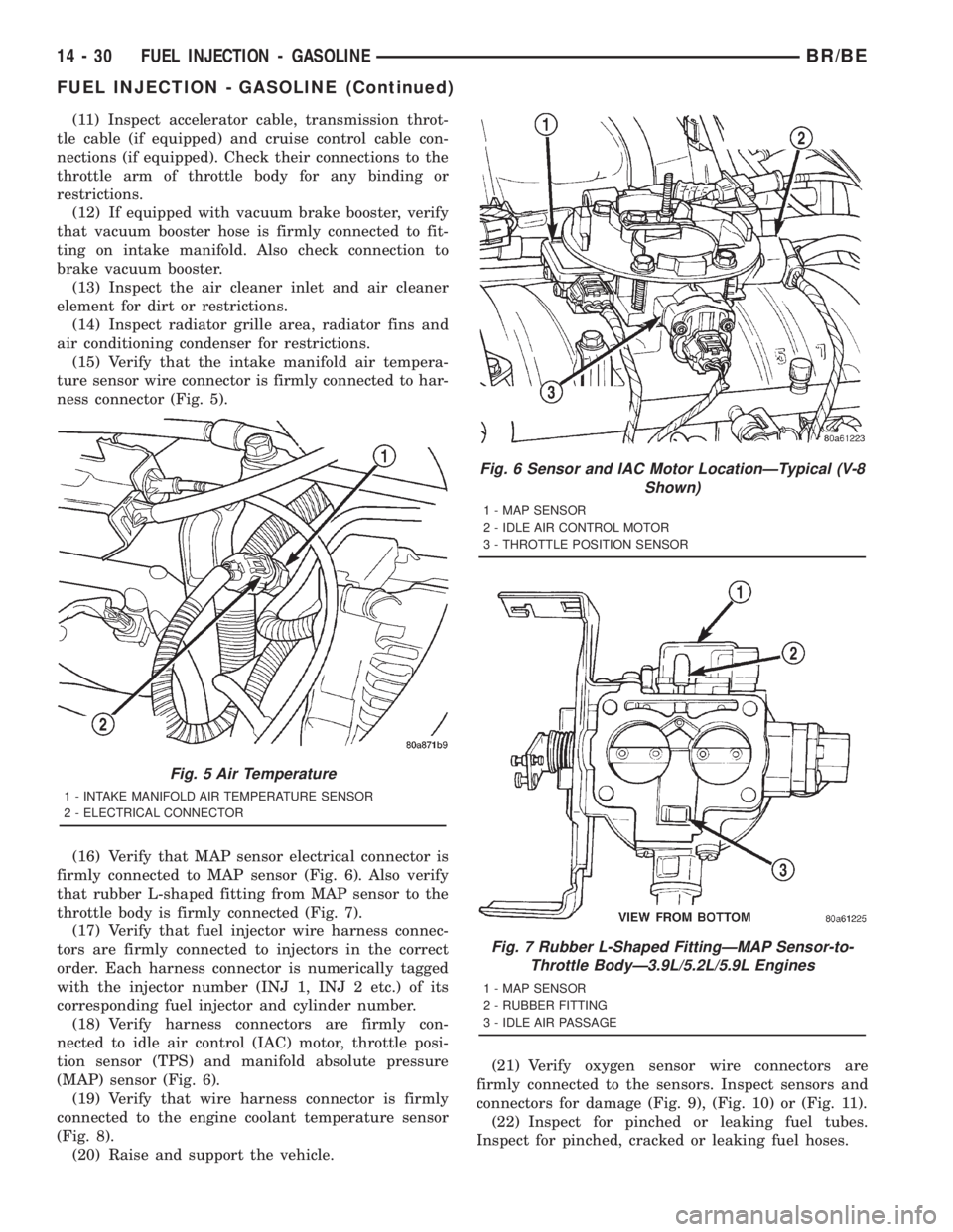
(15) Verify that the intake manifold air tempera-
ture sensor wire connector is firmly connected to har-
ness connector (Fig. 5).
(16) Verify that MAP sensor electrical connector is
firmly connected to MAP sensor (Fig. 6). Also verify
that rubber L-shaped fitting from MAP sensor to the
throttle body is firmly connected (Fig. 7).
(17) Verify that fuel injector wire harness connec-
tors are firmly connected to injectors in the correct
order. Each harness connector is numerically tagged
with the injector number (INJ 1, INJ 2 etc.) of its
corresponding fuel injector and cylinder number.
(18) Verify harness connectors are firmly con-
nected to idle air control (IAC) motor, throttle posi-
tion sensor (TPS) and manifold absolute pressure
(MAP) sensor (Fig. 6).
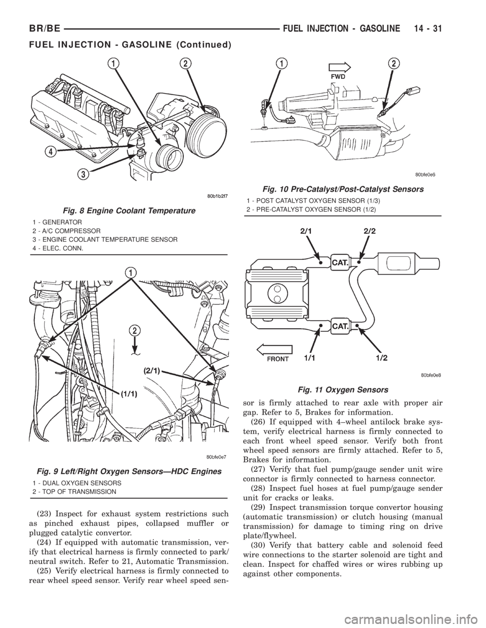
(19) Verify that wire harness connector is firmly
connected to the engine coolant temperature sensor
(Fig. 8).
(20) Raise and support the vehicle.(21) Verify oxygen sensor wire connectors are
firmly connected to the sensors. Inspect sensors and
connectors for damage (Fig. 9), (Fig. 10) or (Fig. 11).
(22) Inspect for pinched or leaking fuel tubes.
Inspect for pinched, cracked or leaking fuel hoses.
Fig. 5 Air Temperature
1 - INTAKE MANIFOLD AIR TEMPERATURE SENSOR
2 - ELECTRICAL CONNECTOR
Fig. 6 Sensor and IAC Motor LocationÐTypical (V-8
Shown)
1 - MAP SENSOR
2 - IDLE AIR CONTROL MOTOR
3 - THROTTLE POSITION SENSOR
Fig. 7 Rubber L-Shaped FittingÐMAP Sensor-to-
Throttle BodyÐ3.9L/5.2L/5.9L Engines
1 - MAP SENSOR
2 - RUBBER FITTING
3 - IDLE AIR PASSAGE
14 - 30 FUEL INJECTION - GASOLINEBR/BE
FUEL INJECTION - GASOLINE (Continued)
Page 1518 of 2889
(23) Inspect for exhaust system restrictions such
as pinched exhaust pipes, collapsed muffler or
plugged catalytic convertor.
(24) If equipped with automatic transmission, ver-
ify that electrical harness is firmly connected to park/
neutral switch. Refer to 21, Automatic Transmission.
(25) Verify electrical harness is firmly connected to
rear wheel speed sensor. Verify rear wheel speed sen-sor is firmly attached to rear axle with proper air
gap. Refer to 5, Brakes for information.
(26) If equipped with 4±wheel antilock brake sys-
tem, verify electrical harness is firmly connected to
each front wheel speed sensor. Verify both front
wheel speed sensors are firmly attached. Refer to 5,
Brakes for information.
(27) Verify that fuel pump/gauge sender unit wire
connector is firmly connected to harness connector.
(28) Inspect fuel hoses at fuel pump/gauge sender
unit for cracks or leaks.
(29) Inspect transmission torque convertor housing
(automatic transmission) or clutch housing (manual
transmission) for damage to timing ring on drive
plate/flywheel.
(30) Verify that battery cable and solenoid feed
wire connections to the starter solenoid are tight and
clean. Inspect for chaffed wires or wires rubbing up
against other components.
Fig. 8 Engine Coolant Temperature
1 - GENERATOR
2 - A/C COMPRESSOR
3 - ENGINE COOLANT TEMPERATURE SENSOR
4 - ELEC. CONN.
Fig. 9 Left/Right Oxygen SensorsÐHDC Engines
1 - DUAL OXYGEN SENSORS
2 - TOP OF TRANSMISSION
Fig. 10 Pre-Catalyst/Post-Catalyst Sensors
1 - POST CATALYST OXYGEN SENSOR (1/3)
2 - PRE-CATALYST OXYGEN SENSOR (1/2)
Fig. 11 Oxygen Sensors
BR/BEFUEL INJECTION - GASOLINE 14 - 31
FUEL INJECTION - GASOLINE (Continued)
Page 1520 of 2889
(12) If equipped with vacuum brake booster, verify
that vacuum booster hose is firmly connected to fit-
ting on intake manifold. Also check connection to
brake vacuum booster.
(13) Inspect the air cleaner inlet and air cleaner
element for dirt or restrictions.
(14) Inspect radiator grille area, radiator fins and
air conditioning condenser for restrictions.
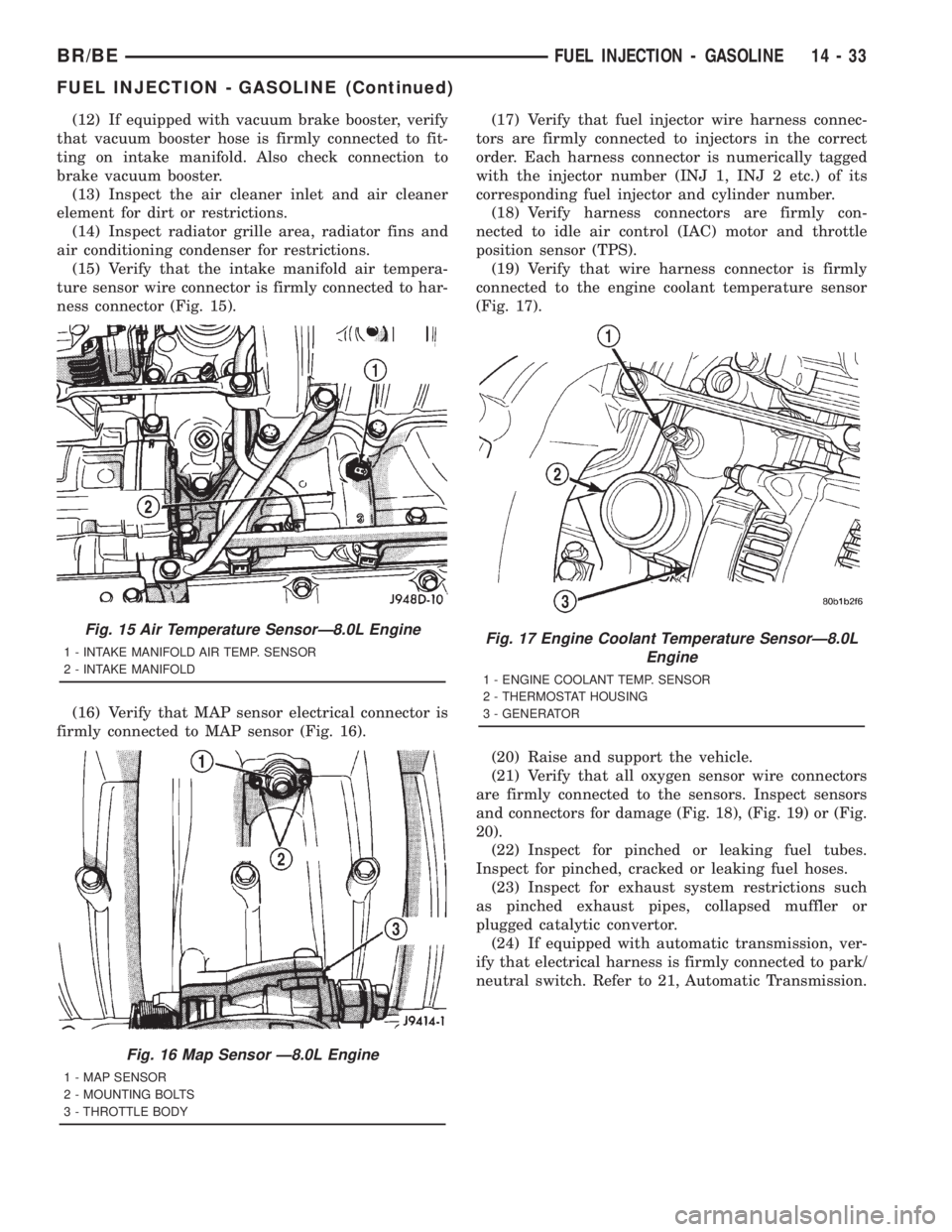
(15) Verify that the intake manifold air tempera-
ture sensor wire connector is firmly connected to har-
ness connector (Fig. 15).
(16) Verify that MAP sensor electrical connector is
firmly connected to MAP sensor (Fig. 16).(17) Verify that fuel injector wire harness connec-
tors are firmly connected to injectors in the correct
order. Each harness connector is numerically tagged
with the injector number (INJ 1, INJ 2 etc.) of its
corresponding fuel injector and cylinder number.
(18) Verify harness connectors are firmly con-
nected to idle air control (IAC) motor and throttle
position sensor (TPS).
(19) Verify that wire harness connector is firmly
connected to the engine coolant temperature sensor
(Fig. 17).
(20) Raise and support the vehicle.
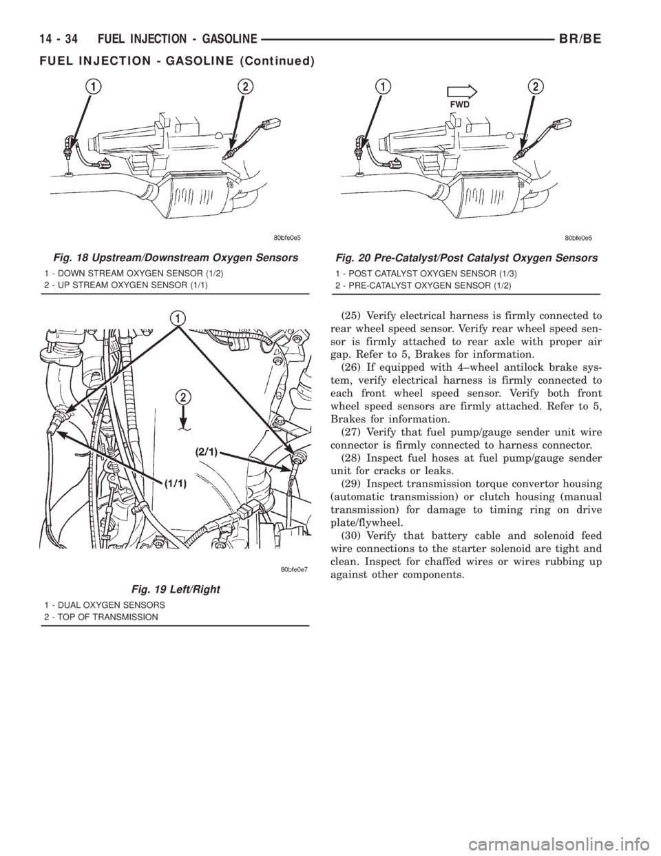
(21) Verify that all oxygen sensor wire connectors
are firmly connected to the sensors. Inspect sensors
and connectors for damage (Fig. 18), (Fig. 19) or (Fig.
20).
(22) Inspect for pinched or leaking fuel tubes.
Inspect for pinched, cracked or leaking fuel hoses.
(23) Inspect for exhaust system restrictions such
as pinched exhaust pipes, collapsed muffler or
plugged catalytic convertor.
(24) If equipped with automatic transmission, ver-
ify that electrical harness is firmly connected to park/
neutral switch. Refer to 21, Automatic Transmission.
Fig. 15 Air Temperature SensorÐ8.0L Engine
1 - INTAKE MANIFOLD AIR TEMP. SENSOR
2 - INTAKE MANIFOLD
Fig. 16 Map Sensor Ð8.0L Engine
1 - MAP SENSOR
2 - MOUNTING BOLTS
3 - THROTTLE BODY
Fig. 17 Engine Coolant Temperature SensorÐ8.0L
Engine
1 - ENGINE COOLANT TEMP. SENSOR
2 - THERMOSTAT HOUSING
3 - GENERATOR
BR/BEFUEL INJECTION - GASOLINE 14 - 33
FUEL INJECTION - GASOLINE (Continued)
Page 1521 of 2889
(25) Verify electrical harness is firmly connected to
rear wheel speed sensor. Verify rear wheel speed sen-
sor is firmly attached to rear axle with proper air
gap. Refer to 5, Brakes for information.
(26) If equipped with 4±wheel antilock brake sys-
tem, verify electrical harness is firmly connected to
each front wheel speed sensor. Verify both front
wheel speed sensors are firmly attached. Refer to 5,
Brakes for information.
(27) Verify that fuel pump/gauge sender unit wire
connector is firmly connected to harness connector.
(28) Inspect fuel hoses at fuel pump/gauge sender
unit for cracks or leaks.
(29) Inspect transmission torque convertor housing
(automatic transmission) or clutch housing (manual
transmission) for damage to timing ring on drive
plate/flywheel.
(30) Verify that battery cable and solenoid feed
wire connections to the starter solenoid are tight and
clean. Inspect for chaffed wires or wires rubbing up
against other components.
Fig. 18 Upstream/Downstream Oxygen Sensors
1 - DOWN STREAM OXYGEN SENSOR (1/2)
2 - UP STREAM OXYGEN SENSOR (1/1)
Fig. 19 Left/Right
1 - DUAL OXYGEN SENSORS
2 - TOP OF TRANSMISSION
Fig. 20 Pre-Catalyst/Post Catalyst Oxygen Sensors
1 - POST CATALYST OXYGEN SENSOR (1/3)
2 - PRE-CATALYST OXYGEN SENSOR (1/2)
14 - 34 FUEL INJECTION - GASOLINEBR/BE
FUEL INJECTION - GASOLINE (Continued)
Page 1559 of 2889
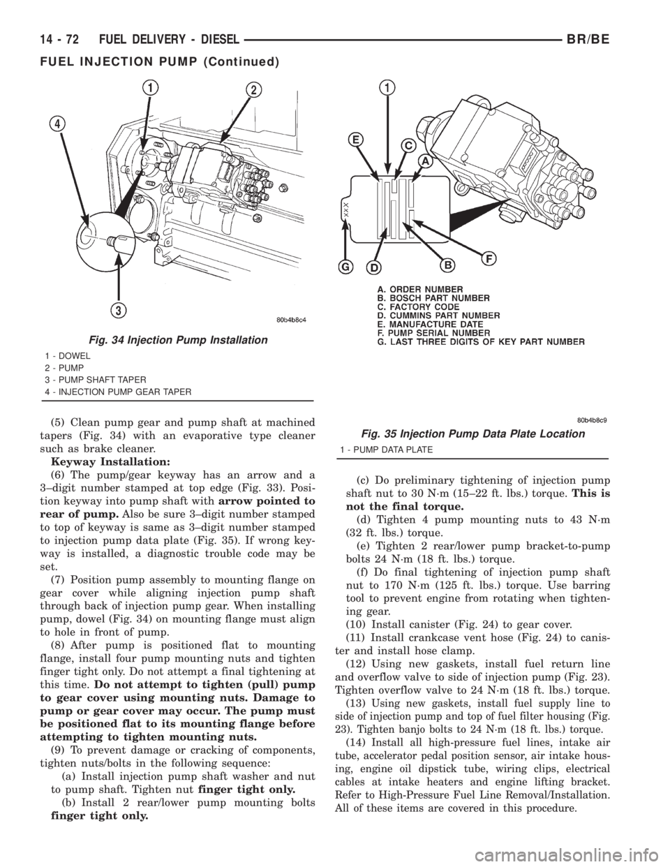
(5) Clean pump gear and pump shaft at machined
tapers (Fig. 34) with an evaporative type cleaner
such as brake cleaner.
Keyway Installation:
(6) The pump/gear keyway has an arrow and a
3±digit number stamped at top edge (Fig. 33). Posi-
tion keyway into pump shaft witharrow pointed to
rear of pump.Also be sure 3±digit number stamped
to top of keyway is same as 3±digit number stamped
to injection pump data plate (Fig. 35). If wrong key-
way is installed, a diagnostic trouble code may be
set.
(7) Position pump assembly to mounting flange on
gear cover while aligning injection pump shaft
through back of injection pump gear. When installing
pump, dowel (Fig. 34) on mounting flange must align
to hole in front of pump.
(8) After pump is positioned flat to mounting
flange, install four pump mounting nuts and tighten
finger tight only. Do not attempt a final tightening at
this time.Do not attempt to tighten (pull) pump
to gear cover using mounting nuts. Damage to
pump or gear cover may occur. The pump must
be positioned flat to its mounting flange before
attempting to tighten mounting nuts.
(9) To prevent damage or cracking of components,
tighten nuts/bolts in the following sequence:
(a) Install injection pump shaft washer and nut
to pump shaft. Tighten nutfinger tight only.
(b) Install 2 rear/lower pump mounting bolts
finger tight only.(c) Do preliminary tightening of injection pump
shaft nut to 30 N´m (15±22 ft. lbs.) torque.This is
not the final torque.
(d) Tighten 4 pump mounting nuts to 43 N´m
(32 ft. lbs.) torque.
(e) Tighten 2 rear/lower pump bracket-to-pump
bolts 24 N´m (18 ft. lbs.) torque.
(f) Do final tightening of injection pump shaft
nut to 170 N´m (125 ft. lbs.) torque. Use barring
tool to prevent engine from rotating when tighten-
ing gear.
(10) Install canister (Fig. 24) to gear cover.
(11) Install crankcase vent hose (Fig. 24) to canis-
ter and install hose clamp.
(12) Using new gaskets, install fuel return line
and overflow valve to side of injection pump (Fig. 23).
Tighten overflow valve to 24 N´m (18 ft. lbs.) torque.
(13)
Using new gaskets, install fuel supply line to
side of injection pump and top of fuel filter housing (Fig.
23). Tighten banjo bolts to 24 N´m (18 ft. lbs.) torque.
(14)Install all high-pressure fuel lines, intake air
tube, accelerator pedal position sensor, air intake hous-
ing, engine oil dipstick tube, wiring clips, electrical
cables at intake heaters and engine lifting bracket.
Refer to High-Pressure Fuel Line Removal/Installation.
All of these items are covered in this procedure.
Fig. 34 Injection Pump Installation
1 - DOWEL
2 - PUMP
3 - PUMP SHAFT TAPER
4 - INJECTION PUMP GEAR TAPER
Fig. 35 Injection Pump Data Plate Location
1 - PUMP DATA PLATE
14 - 72 FUEL DELIVERY - DIESELBR/BE
FUEL INJECTION PUMP (Continued)
Page 1597 of 2889
CONDITION POSSIBLE CAUSE CORRECTION
VEHICLE PULLS OR LEADS TO
ONE SIDE.1. Tire Pressure. 1. Adjust tire pressure.
2. Radial tire lead. 2. Rotate tires.
3. Brakes dragging. 3. Repair as necessary.
4. Wheel alignment. 4. Align front end.
DIAGNOSIS AND TESTING - POWER STEERING
FLOW AND PRESSURE
The following procedure is used to test the opera-
tion of the power steering system on the vehicle. This
test will provide the flow rate of the power steering
pump along with the maximum relief pressure. Per-
form test any time a power steering system problem
is present. This test will determine if the power
steering pump or power steering gear is not function-
ing properly. The following pressure and flow test is
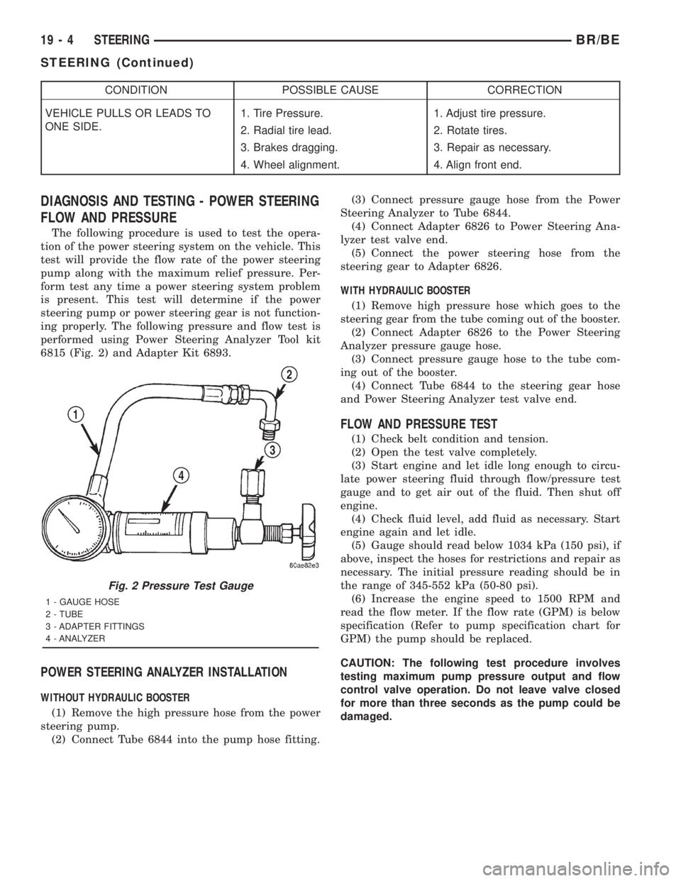
performed using Power Steering Analyzer Tool kit
6815 (Fig. 2) and Adapter Kit 6893.
POWER STEERING ANALYZER INSTALLATION
WITHOUT HYDRAULIC BOOSTER
(1) Remove the high pressure hose from the power
steering pump.
(2) Connect Tube 6844 into the pump hose fitting.(3) Connect pressure gauge hose from the Power
Steering Analyzer to Tube 6844.
(4) Connect Adapter 6826 to Power Steering Ana-
lyzer test valve end.
(5) Connect the power steering hose from the
steering gear to Adapter 6826.
WITH HYDRAULIC BOOSTER
(1) Remove high pressure hose which goes to the
steering gear from the tube coming out of the booster.
(2) Connect Adapter 6826 to the Power Steering
Analyzer pressure gauge hose.
(3) Connect pressure gauge hose to the tube com-
ing out of the booster.
(4) Connect Tube 6844 to the steering gear hose
and Power Steering Analyzer test valve end.
FLOW AND PRESSURE TEST
(1) Check belt condition and tension.
(2) Open the test valve completely.
(3) Start engine and let idle long enough to circu-
late power steering fluid through flow/pressure test
gauge and to get air out of the fluid. Then shut off
engine.
(4) Check fluid level, add fluid as necessary. Start
engine again and let idle.
(5) Gauge should read below 1034 kPa (150 psi), if
above, inspect the hoses for restrictions and repair as
necessary. The initial pressure reading should be in
the range of 345-552 kPa (50-80 psi).
(6) Increase the engine speed to 1500 RPM and
read the flow meter. If the flow rate (GPM) is below
specification (Refer to pump specification chart for
GPM) the pump should be replaced.
CAUTION: The following test procedure involves
testing maximum pump pressure output and flow
control valve operation. Do not leave valve closed
for more than three seconds as the pump could be
damaged.
Fig. 2 Pressure Test Gauge
1 - GAUGE HOSE
2 - TUBE
3 - ADAPTER FITTINGS
4 - ANALYZER
19 - 4 STEERINGBR/BE
STEERING (Continued)
Page 1603 of 2889
DIAGNOSIS AND TESTING - IGNITION SWITCH
AND KEY LOCK CYLINDER
ELECTRICAL DIAGNOSIS
For ignition switch electrical schematics, refer to
Ignition Switch in the appropriate section of Electri-
cal Wiring Diagrams.
MECHANICAL DIAGNOSIS (KEY DIFFICULT TO
ROTATE)
Vehicles equipped with an automatic trans-
mission and a floor mounted shifter:a cable is
used to connect the interlock device in the steering
column assembly, to the transmission floor shift
lever. This interlock device is used to lock the trans-
mission shifter in the PARK position when the key
lock cylinder is rotated to the LOCKED or ACCES-
SORY position. The interlock device within the steer-
ing column is not serviceable. If repair is necessary,
the steering column assembly must be replaced.
(Refer to 19 - STEERING/COLUMN - REMOVAL).
If the ignition key is difficult to rotate to or from
the LOCK or ACCESSORY position, it may not be
the fault of the key cylinder or the steering column
components. The brake transmission shift interlock
cable may be out of adjustment. Refer to Brake
Transmission Shift Interlock Cable Adjustment in
Transmissions for adjustment procedures.
Vehicles equipped with an automatic trans-
mission and a steering column mounted shifter:
an interlock device is located within the steering col-
umn. This interlock device is used to lock the trans-
mission shifter in the PARK position when the key
lock cylinder is in the LOCKED or ACCESSORY
position. If it is difficult to rotate the key to or from
the LOCK or ACCESSORY position, the interlock
device within the steering column may be defective.
This device is not serviceable. If repair is necessary,
the steering column assembly must be replaced.
(Refer to 19 - STEERING/COLUMN - REMOVAL).
Vehicles equipped with a manual transmis-
sion and a floor mounted shifter:on certain mod-
els, a lever is located on the steering column behind
the ignition key lock cylinder. The lever must be
manually operated to allow rotation of the ignition
key lock cylinder to the LOCK or ACCESSORY posi-
tion. If it is difficult to rotate the key to the LOCK or
ACCESSORY position, the lever mechanism may be
defective. This mechanism is not serviceable. If
repair is necessary, the steering column assembly
must be replaced. (Refer to 19 - STEERING/COL-
UMN - REMOVAL).
On other models, the ignition key cylinder must be
depressed to allow it to be rotated into the LOCK or
ACCESSORY position. If it is difficult to rotate the
key to the LOCK or ACCESSORY position, the lockmechanism within the steering column may be defec-
tive. This mechanism is not serviceable. If repair is
necessary, the steering column assembly must be
replaced. (Refer to 19 - STEERING/COLUMN -
REMOVAL).
LOCK CYLINDER HOUSING
REMOVAL
The ignition key must be in the key cylinder for
cylinder removal.
(1) Disconnect negative cable from battery.
(2) If equipped with tilt column, remove tilt lever
by turning it counterclockwise.
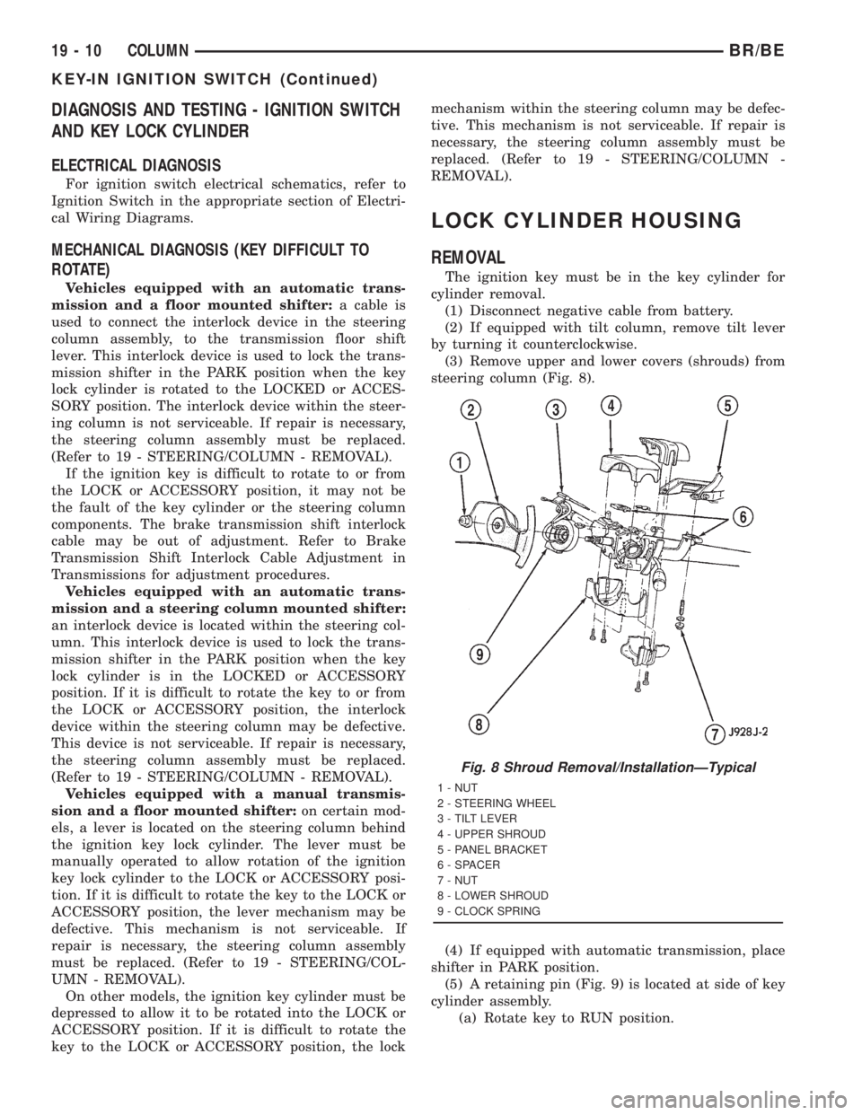
(3) Remove upper and lower covers (shrouds) from
steering column (Fig. 8).
(4) If equipped with automatic transmission, place
shifter in PARK position.
(5) A retaining pin (Fig. 9) is located at side of key
cylinder assembly.
(a) Rotate key to RUN position.
Fig. 8 Shroud Removal/InstallationÐTypical
1 - NUT
2 - STEERING WHEEL
3 - TILT LEVER
4 - UPPER SHROUD
5 - PANEL BRACKET
6 - SPACER
7 - NUT
8 - LOWER SHROUD
9 - CLOCK SPRING
19 - 10 COLUMNBR/BE
KEY-IN IGNITION SWITCH (Continued)
Page 1604 of 2889
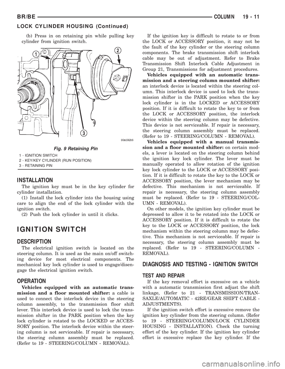
(b) Press in on retaining pin while pulling key
cylinder from ignition switch.
INSTALLATION
The ignition key must be in the key cylinder for
cylinder installation.
(1) Install the lock cylinder into the housing using
care to align the end of the lock cylinder with the
ignition switch.
(2) Push the lock cylinder in until it clicks.
IGNITION SWITCH
DESCRIPTION
The electrical ignition switch is located on the
steering column. It is used as the main on/off switch-
ing device for most electrical components. The
mechanical key lock cylinder is used to engage/disen-
gage the electrical ignition switch.
OPERATION
Vehicles equipped with an automatic trans-
mission and a floor mounted shifter:a cable is
used to connect the interlock device in the steering
column assembly, to the transmission floor shift
lever. This interlock device is used to lock the trans-
mission shifter in the PARK position when the key
lock cylinder is rotated to the LOCKED or ACCES-
SORY position. The interlock device within the steer-
ing column is not serviceable. If repair is necessary,
the steering column assembly must be replaced.
(Refer to 19 - STEERING/COLUMN - REMOVAL).If the ignition key is difficult to rotate to or from
the LOCK or ACCESSORY position, it may not be
the fault of the key cylinder or the steering column
components. The brake transmission shift interlock
cable may be out of adjustment. Refer to Brake
Transmission Shift Interlock Cable Adjustment in
Group 21, Transmissions for adjustment procedures.
Vehicles equipped with an automatic trans-
mission and a steering column mounted shifter:
an interlock device is located within the steering col-
umn. This interlock device is used to lock the trans-
mission shifter in the PARK position when the key
lock cylinder is in the LOCKED or ACCESSORY
position. If it is difficult to rotate the key to or from
the LOCK or ACCESSORY position, the interlock
device within the steering column may be defective.
This device is not serviceable. If repair is necessary,
the steering column assembly must be replaced.
(Refer to 19 - STEERING/COLUMN - REMOVAL).
Vehicles equipped with a manual transmis-
sion and a floor mounted shifter:on certain mod-
els, a lever is located on the steering column behind
the ignition key lock cylinder. The lever must be
manually operated to allow rotation of the ignition
key lock cylinder to the LOCK or ACCESSORY posi-
tion. If it is difficult to rotate the key to the LOCK or
ACCESSORY position, the lever mechanism may be
defective. This mechanism is not serviceable. If
repair is necessary, the steering column assembly
must be replaced. (Refer to 19 - STEERING/COL-
UMN - REMOVAL).
On other models, the ignition key cylinder must be
depressed to allow it to be rotated into the LOCK or
ACCESSORY position. If it is difficult to rotate the
key to the LOCK or ACCESSORY position, the lock
mechanism within the steering column may be defec-
tive. This mechanism is not serviceable. If repair is
necessary, the steering column assembly must be
replaced. (Refer to 19 - STEERING/COLUMN -
REMOVAL).
DIAGNOSIS AND TESTING - IGNITION SWITCH
TEST AND REPAIR
If the key removal effort is excessive on a vehicle
with a automatic transmission first adjust the shift
linkage, (Refer to 21 - TRANSMISSION/TRAN-
SAXLE/AUTOMATIC - 42RE/GEAR SHIFT CABLE -
ADJUSTMENTS).
If the ignition switch effort is excessive remove the
ignition key cylinder from the steering column. (Refer
to 19 - STEERING/COLUMN/LOCK CYLINDER
HOUSING - INSTALLATION). Check the turning
effort of the key cylinder. If the ignition key cylinder
effort is excessive replace the key cylinder. If the
Fig. 9 Retaining Pin
1 - IGNITION SWITCH
2 - KEY/KEY CYLINDER (RUN POSITION)
3 - RETAINING PIN
BR/BECOLUMN 19 - 11
LOCK CYLINDER HOUSING (Continued)