2001 DODGE RAM brake
[x] Cancel search: brakePage 1083 of 2889
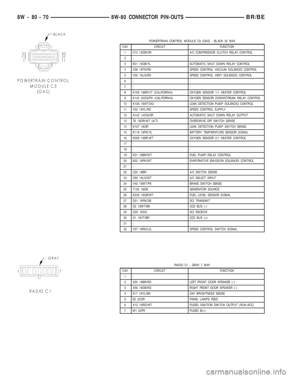
POWERTRAIN CONTROL MODULE C3 (GAS) - BLACK 32 WAY
CAV CIRCUIT FUNCTION
1 C13 18DB/OR A/C COMPRESSOR CLUTCH RELAY CONTROL
2- -
3 K51 18DB/YL AUTOMATIC SHUT DOWN RELAY CONTROL
4 V36 18TN/RD SPEED CONTROL VACUUM SOLENOID CONTROL
5 V35 18LG/RD SPEED CONTROL VENT SOLENOID CONTROL
6- -
7- -
8 K199 18BR/VT (CALIFORNIA) OXYGEN SENSOR 1/1 HEATER CONTROL
9 K145 20DG/PK (CALIFORNIA) OXYGEN SENSOR DOWNSTREAM RELAY CONTROL
10 K106 18WT/DG LEAK DETECTION PUMP SOLENOID CONTROL
11 V32 18YL/RD SPEED CONTROL SUPPLY
12 A142 14DG/OR AUTOMATIC SHUT DOWN RELAY OUTPUT
13 T6 18OR/WT (A/T) OVERDRIVE OFF SWITCH SENSE
14 K107 18OR LEAK DETECTION PUMP SWITCH SENSE
15 K118 18PK/YL BATTERY TEMPERATURE SENSOR SIGNAL
16 K299 18BR.WT OXYGEN SENSOR 2/1 HEATER CONTROL
17 - -
18 - -
19 K31 18BR/WT FUEL PUMP RELAY CONTROL
20 K52 18PK/WT EVAPORATIVE EMISSION SOLENOID CONTROL
21 - -
22 C20 18BR A/C SWITCH SENSE
23 C90 18LG/WT A/C SELECT INPUT
24 V40 18WT/PK BRAKE SWITCH SENSE
25 T125 18DB GENERATOR SOURCE
26 K226 18DB/WT FUEL LEVEL SENSOR SIGNAL
27 D21 18PK/DB SCI TRANSMIT
28 D2 18WT/BK CCD BUS (-)
29 D20 18DG SCI RECEIVE
30 D1 18VT/BR CCD BUS (+)
31 - -
32 V37 18RD/LG SPEED CONTROL SWITCH SIGNAL
RADIO C1 - GRAY 7 WAY
CAV CIRCUIT FUNCTION
1- -
2 X55 18BR/RD LEFT FRONT DOOR SPEAKER (-)
3 X56 18DB/RD RIGHT FRONT DOOR SPEAKER (-)
4 E17 18YL/BK DAY BRIGHTNESS SENSE
5 E2 22OR PANEL LAMPS FEED
6 X12 16RD/WT FUSED IGNITION SWITCH OUTPUT (RUN-ACC)
7 M1 22PK FUSED B(+)
8W - 80 - 70 8W-80 CONNECTOR PIN-OUTSBR/BE
Page 1089 of 2889
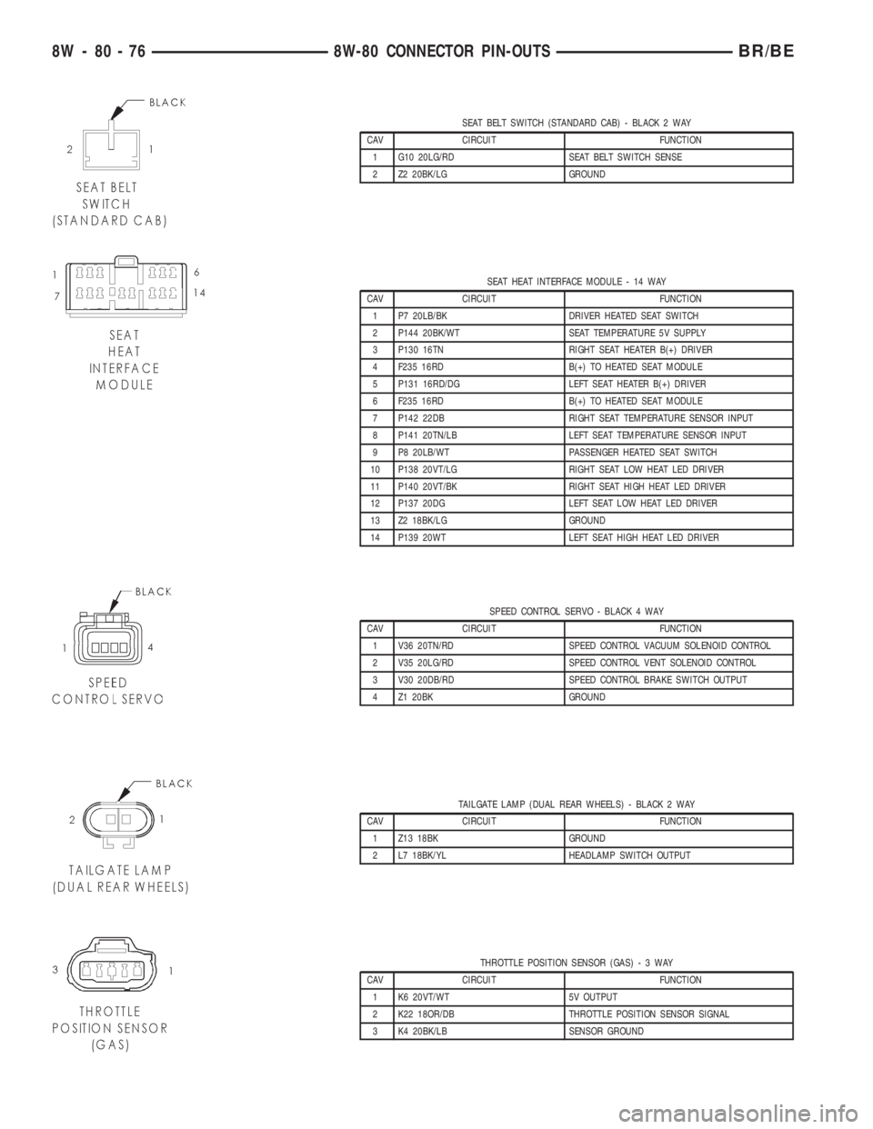
SEAT BELT SWITCH (STANDARD CAB) - BLACK 2 WAY
CAV CIRCUIT FUNCTION
1 G10 20LG/RD SEAT BELT SWITCH SENSE
2 Z2 20BK/LG GROUND
SEAT HEAT INTERFACE MODULE - 14 WAY
CAV CIRCUIT FUNCTION
1 P7 20LB/BK DRIVER HEATED SEAT SWITCH
2 P144 20BK/WT SEAT TEMPERATURE 5V SUPPLY
3 P130 16TN RIGHT SEAT HEATER B(+) DRIVER
4 F235 16RD B(+) TO HEATED SEAT MODULE
5 P131 16RD/DG LEFT SEAT HEATER B(+) DRIVER
6 F235 16RD B(+) TO HEATED SEAT MODULE
7 P142 22DB RIGHT SEAT TEMPERATURE SENSOR INPUT
8 P141 20TN/LB LEFT SEAT TEMPERATURE SENSOR INPUT
9 P8 20LB/WT PASSENGER HEATED SEAT SWITCH
10 P138 20VT/LG RIGHT SEAT LOW HEAT LED DRIVER
11 P140 20VT/BK RIGHT SEAT HIGH HEAT LED DRIVER
12 P137 20DG LEFT SEAT LOW HEAT LED DRIVER
13 Z2 18BK/LG GROUND
14 P139 20WT LEFT SEAT HIGH HEAT LED DRIVER
SPEED CONTROL SERVO - BLACK 4 WAY
CAV CIRCUIT FUNCTION
1 V36 20TN/RD SPEED CONTROL VACUUM SOLENOID CONTROL
2 V35 20LG/RD SPEED CONTROL VENT SOLENOID CONTROL
3 V30 20DB/RD SPEED CONTROL BRAKE SWITCH OUTPUT
4 Z1 20BK GROUND
TAILGATE LAMP (DUAL REAR WHEELS) - BLACK 2 WAY
CAV CIRCUIT FUNCTION
1 Z13 18BK GROUND
2 L7 18BK/YL HEADLAMP SWITCH OUTPUT
THROTTLE POSITION SENSOR (GAS)-3WAY
CAV CIRCUIT FUNCTION
1 K6 20VT/WT 5V OUTPUT
2 K22 18OR/DB THROTTLE POSITION SENSOR SIGNAL
3 K4 20BK/LB SENSOR GROUND
8W - 80 - 76 8W-80 CONNECTOR PIN-OUTSBR/BE
Page 1090 of 2889
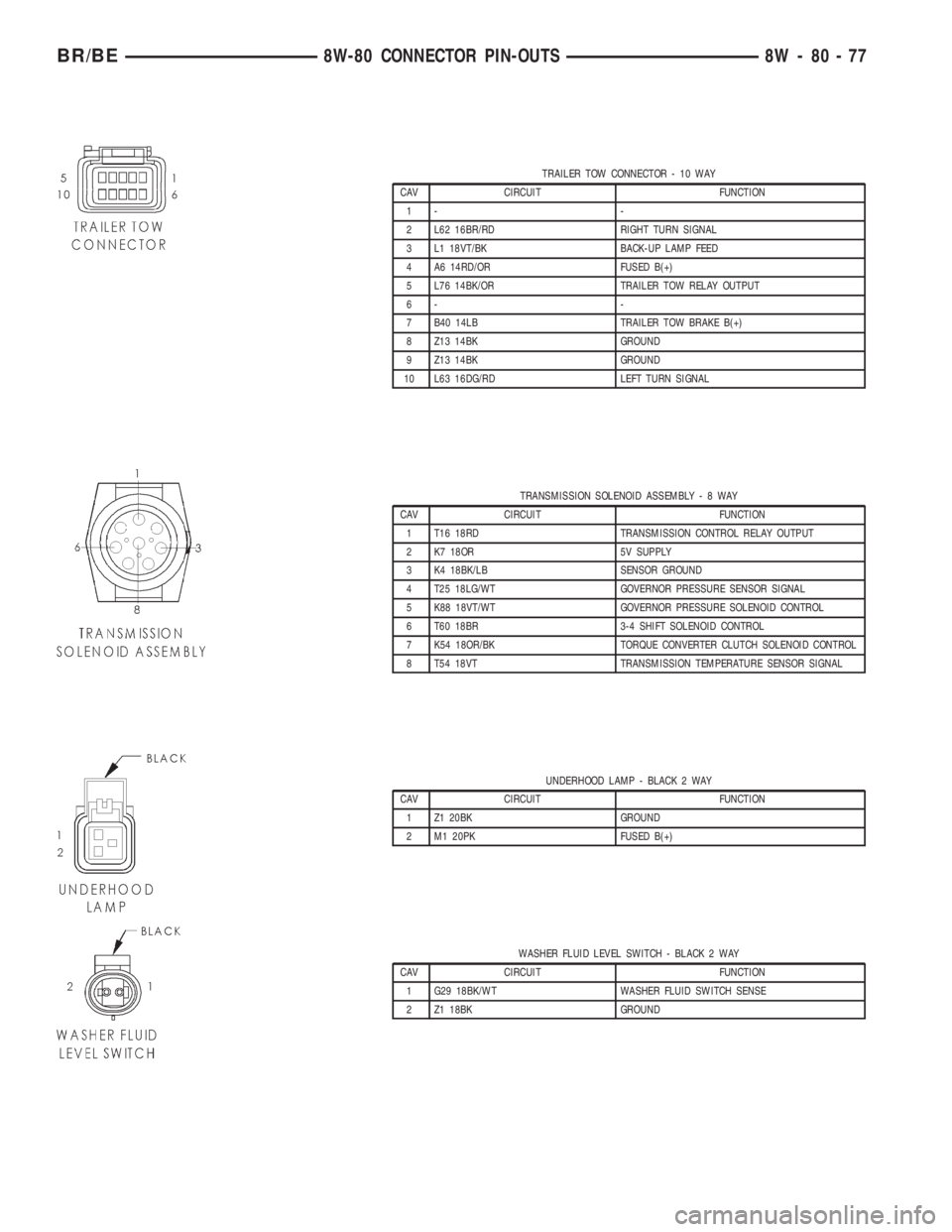
TRAILER TOW CONNECTOR - 10 WAY
CAV CIRCUIT FUNCTION
1- -
2 L62 16BR/RD RIGHT TURN SIGNAL
3 L1 18VT/BK BACK-UP LAMP FEED
4 A6 14RD/OR FUSED B(+)
5 L76 14BK/OR TRAILER TOW RELAY OUTPUT
6- -
7 B40 14LB TRAILER TOW BRAKE B(+)
8 Z13 14BK GROUND
9 Z13 14BK GROUND
10 L63 16DG/RD LEFT TURN SIGNAL
TRANSMISSION SOLENOID ASSEMBLY-8WAY
CAV CIRCUIT FUNCTION
1 T16 18RD TRANSMISSION CONTROL RELAY OUTPUT
2 K7 18OR 5V SUPPLY
3 K4 18BK/LB SENSOR GROUND
4 T25 18LG/WT GOVERNOR PRESSURE SENSOR SIGNAL
5 K88 18VT/WT GOVERNOR PRESSURE SOLENOID CONTROL
6 T60 18BR 3-4 SHIFT SOLENOID CONTROL
7 K54 18OR/BK TORQUE CONVERTER CLUTCH SOLENOID CONTROL
8 T54 18VT TRANSMISSION TEMPERATURE SENSOR SIGNAL
UNDERHOOD LAMP - BLACK 2 WAY
CAV CIRCUIT FUNCTION
1 Z1 20BK GROUND
2 M1 20PK FUSED B(+)
WASHER FLUID LEVEL SWITCH - BLACK 2 WAY
CAV CIRCUIT FUNCTION
1 G29 18BK/WT WASHER FLUID SWITCH SENSE
2 Z1 18BK GROUND
BR/BE8W-80 CONNECTOR PIN-OUTS 8W - 80 - 77
Page 1092 of 2889
8W-90 CONNECTOR/GROUND LOCATIONS
TABLE OF CONTENTS
page
CONNECTOR/GROUND LOCATIONS
DESCRIPTION............................1
CONNECTOR/GROUND
LOCATIONS
DESCRIPTION
This section provides illustrations identifying con-
nector and ground locations in the vehicle. A connec-tor and ground index is provided. Use the wiring
diagrams in each section for connector and ground
identification. Refer to the index for the proper figure
number. For items that are not shown in this section
N/S is placed in the Fig. column.
Connector Name/Number Color Location Fig.
4WD Switch BK On Front Axle N/S
A/C Compressor Clutch BK Rear of A/C Compressor 4,5,6,8
A/C Heater Control BK Center of Instrument Panel 25
A/C Heater Temperature Select NAT Center of Instrument Panel 25
A/C High Pressure Switch BK At A/C Compressor 4,5,6,8
A/C Low Pressure Switch BK Top of A/C Accumulator 1,2
Accelerator Pedal Position Sensor (Diesel) Left Front of Engine 10,11
Aftermarket Trailer Tow Connector Rear of Vehicle N/S
Airbag Control Module Center of I.P. at Airbag Control
Module23
Ambient Temperature Sensor BK Radiator Left Support N/S
Ash Receiver Lamp Center of Instrument Panel 26
Back-up Lamp Switch BK Top of Transmission 13
Battery Temperature Sensor BK Below Battery Tray 16
Blend Door Actuator Center of Instrument Panel N/S
Blower Motor BK Bottom Right of Instrument Panel 23
Blower Motor Resistor Block BK Bottom Right of Instrument Panel 26
Brake Lamp Switch Brake Pedal Arm 23,24
Brake Pressure Switch At Master Cylinder 14
Bypass Jumper GN Top Of Clutch Pedal 27
C105 Rear of Front Bumper N/S
C106 BK Rear of Front Bumper 17
C114 BK Radiator Left Support 15
C125 (Diesel) BK Left Rear of Engine Compartment 2
C126 (Diesel) GY Left Rear of Engine Compartment 2
C129 BK Above Left Front Body Cushion 15,22
C130 At Power Distribution Center 1,2
C134 BK Left Cowl 23,25,27
BR/BE8W-90 CONNECTOR/GROUND LOCATIONS 8W - 90 - 1
Page 1093 of 2889
Connector Name/Number Color Location Fig.
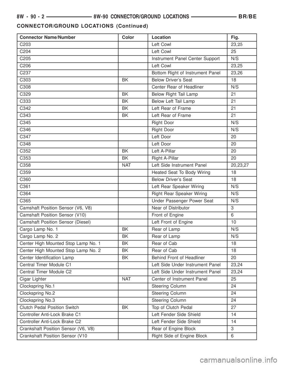
C203 Left Cowl 23,25
C204 Left Cowl 25
C205 Instrument Panel Center Support N/S
C206 Left Cowl 23,25
C237 Bottom Right of Instrument Panel 23,26
C303 BK Below Driver's Seat 18
C308 Center Rear of Headliner N/S
C329 BK Below Right Tail Lamp 21
C333 BK Below Left Tail Lamp 21
C342 BK Left Rear of Frame 21
C343 BK Left Rear of Frame 21
C345 Right Door N/S
C346 Right Door N/S
C347 Left Door 20
C348 Left Door 20
C352 BK Left A-Pillar 20
C353 BK Right A-Pillar 20
C358 NAT Left Side Instrument Panel 20,23,27
C359 Heated Seat To Body Wiring 18
C360 Below Driver's Seat 18
C361 Left Rear Speaker Wiring N/S
C364 Right Rear Speaker Wiring N/S
C365 Under Passenger Power Seat N/S
Camshaft Position Sensor (V6, V8) Near of Distributor 3
Camshaft Position Sensor (V10) Front of Engine 6
Camshaft Position Sensor (Diesel) Left Front of Engine 10
Cargo Lamp No. 1 BK Rear of Lamp N/S
Cargo Lamp No. 2 BK Rear of Lamp N/S
Center High Mounted Stop Lamp No. 1 BK Rear of Cab 18
Center High Mounted Stop Lamp No. 2 BK Rear of Cab 18
Center Identification Lamp BK Behind Front of Headliner 20
Central Timer Module C1 Left Side Under Instrument Panel 23,24
Central Timer Module C2 Left Side Under Instrument Panel 23,24
Cigar Lighter NAT Center of Instrument Panel 25
Clockspring No.1 Steering Column 24
Clockspring No.2 Steering Column 24
Clockspring No.3 Steering Column 24
Clutch Pedal Position Switch BK Top of Clutch Pedal 27
Controller Anti-Lock Brake C1 Left Fender Side Shield 14
Controller Anti-Lock Brake C2 Left Fender Side Shield 14
Crankshaft Position Sensor (V6, V8) Rear of Engine Block 3
Crankshaft Position Sensor (V10 Right Side of Engine Block 6
8W - 90 - 2 8W-90 CONNECTOR/GROUND LOCATIONSBR/BE
CONNECTOR/GROUND LOCATIONS (Continued)
Page 1094 of 2889

Connector Name/Number Color Location Fig.
Cummins Bus (-) Left Front of Engine 10
Cup Holder Lamp Center of Instrument Panel 23,26
Data Link Connector BK Left Bottom of Instrument Panel 23,24
Day/Night Mirror BK Day/Night Mirror N/S
Daytime Running Lamp Module BK Left Fender Side Shield 14
Dome Lamp Rear of Cab 18
Driver Airbag BK Steering Wheel N/S
Driver Door Arm/Disarm Switch BK In Door 19
Driver Door Jamb Switch NAT Door Jamb 19
Driver Door Lock Motor BK In Door 19
Driver Door Window/Lock Switch BL In Door 19
Driver Heated Seat Module BL Under Seat N/S
Driver Heated Seat Switch RD Center of Instrument Panel N/S
Driver Lumbar Motor Under Seat N/S
Driver Power Seat Front Vertical Motor BK Under Seat N/S
Driver Power Seat Horizontal Motor BK Under Seat N/S
Driver Power Seat Rear Vertical Motor Under Seat N/S
Driver Power Seat Switch At Seat N/S
Driver Power Window Motor In Door 19
Duty Cycle EVAP/Purge Solenoid BK Right Fender Side Shield 17
Electric Brake Provision Bottom Left of Instrument Panel N/S
Engine Control Module (Diesel) Left Side Engine 12
Engine Coolant Temperature Sensor (Diesel) BK Left Front of Cylinder Head
(Diesel)10
Engine Coolant Temperature Sensor (Gas) BK On Thermostat Housing 3,6
Engine Oil Pressure Sensor (V6, V8) BK Near Distributor 3
Engine Oil Pressure Sensor (V10) Near Oil Filter 6
Engine Oil Pressure Sensor (Diesel) Left Side of Engine 12
Fuel Heater (Diesel) Left Side of Engine 10
Fuel Injection Pump (Diesel) Left Side of Engine, Below ECM 10
Fuel Injector No.1 BK At Fuel Injector 4,5
Fuel Injector No. 2 BK At Fuel Injector 4,5,6
Fuel Injector No. 3 BK At Fuel Injector 4,5,6
Fuel Injector No. 4 BK At Fuel Injector 4,5,6
Fuel Injector No. 5 BK At Fuel Injector 4,5,6
Fuel Injector No. 6 BK At Fuel Injector 4,5,6
Fuel Injector No. 7 BK At Fuel Injector 4,6
Fuel Injector No. 8 BK At Fuel Injector 4,6
Fuel Injector No. 9 BK At Fuel Injector 6
Fuel Injector No. 10 BK At Fuel Injector 6
Fuel Pump Module LTGY At Frame Rail 22
Fuel Transfer Pump (Diesel) Left Rear of Engine Bottom of
Pump10
BR/BE8W-90 CONNECTOR/GROUND LOCATIONS 8W - 90 - 3
CONNECTOR/GROUND LOCATIONS (Continued)
Page 1124 of 2889
8W-95 SPLICE LOCATIONS
TABLE OF CONTENTS
page
SPLICE LOCATIONS
DESCRIPTION............................1
SPLICE LOCATIONS
DESCRIPTION
This section provides illustrations identifying the
general location of the splices in this vehicle. A spliceindex is provided. Use the wiring diagrams in each
section for splice number identification. Refer to the
index for proper splice number. For splices that are
not shown in the figures N/S appears in the Fig. col-
umn.
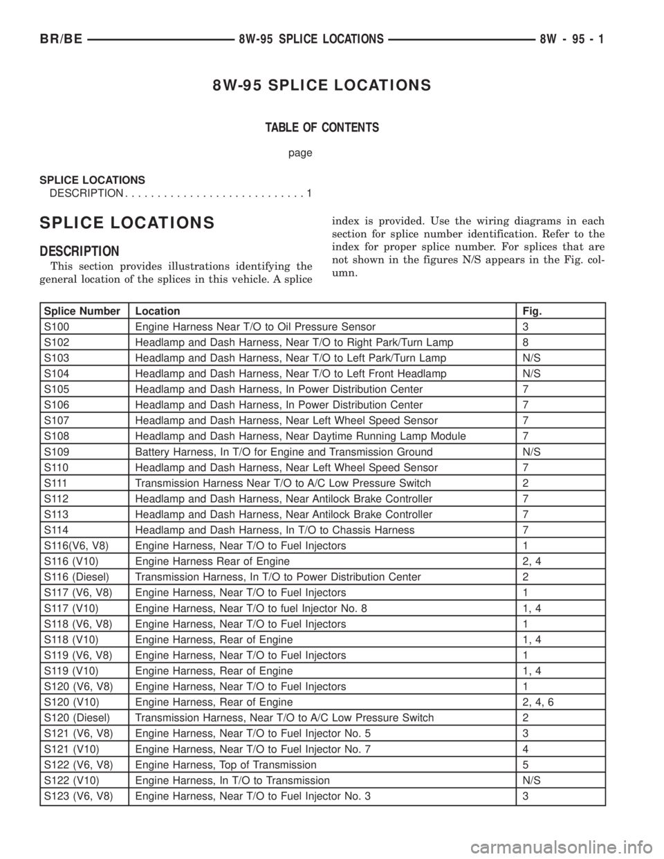
Splice Number Location Fig.
S100 Engine Harness Near T/O to Oil Pressure Sensor 3
S102 Headlamp and Dash Harness, Near T/O to Right Park/Turn Lamp 8
S103 Headlamp and Dash Harness, Near T/O to Left Park/Turn Lamp N/S
S104 Headlamp and Dash Harness, Near T/O to Left Front Headlamp N/S
S105 Headlamp and Dash Harness, In Power Distribution Center 7
S106 Headlamp and Dash Harness, In Power Distribution Center 7
S107 Headlamp and Dash Harness, Near Left Wheel Speed Sensor 7
S108 Headlamp and Dash Harness, Near Daytime Running Lamp Module 7
S109 Battery Harness, In T/O for Engine and Transmission Ground N/S
S110 Headlamp and Dash Harness, Near Left Wheel Speed Sensor 7
S111 Transmission Harness Near T/O to A/C Low Pressure Switch 2
S112 Headlamp and Dash Harness, Near Antilock Brake Controller 7
S113 Headlamp and Dash Harness, Near Antilock Brake Controller 7
S114 Headlamp and Dash Harness, In T/O to Chassis Harness 7
S116(V6, V8) Engine Harness, Near T/O to Fuel Injectors 1
S116 (V10) Engine Harness Rear of Engine 2, 4
S116 (Diesel) Transmission Harness, In T/O to Power Distribution Center 2
S117 (V6, V8) Engine Harness, Near T/O to Fuel Injectors 1
S117 (V10) Engine Harness, Near T/O to fuel Injector No. 8 1, 4
S118 (V6, V8) Engine Harness, Near T/O to Fuel Injectors 1
S118 (V10) Engine Harness, Rear of Engine 1, 4
S119 (V6, V8) Engine Harness, Near T/O to Fuel Injectors 1
S119 (V10) Engine Harness, Rear of Engine 1, 4
S120 (V6, V8) Engine Harness, Near T/O to Fuel Injectors 1
S120 (V10) Engine Harness, Rear of Engine 2, 4, 6
S120 (Diesel) Transmission Harness, Near T/O to A/C Low Pressure Switch 2
S121 (V6, V8) Engine Harness, Near T/O to Fuel Injector No. 5 3
S121 (V10) Engine Harness, Near T/O to Fuel Injector No. 7 4
S122 (V6, V8) Engine Harness, Top of Transmission 5
S122 (V10) Engine Harness, In T/O to Transmission N/S
S123 (V6, V8) Engine Harness, Near T/O to Fuel Injector No. 3 3
BR/BE8W-95 SPLICE LOCATIONS 8W - 95 - 1
Page 1400 of 2889
CYLINDER HEAD COVER(S)
REMOVAL
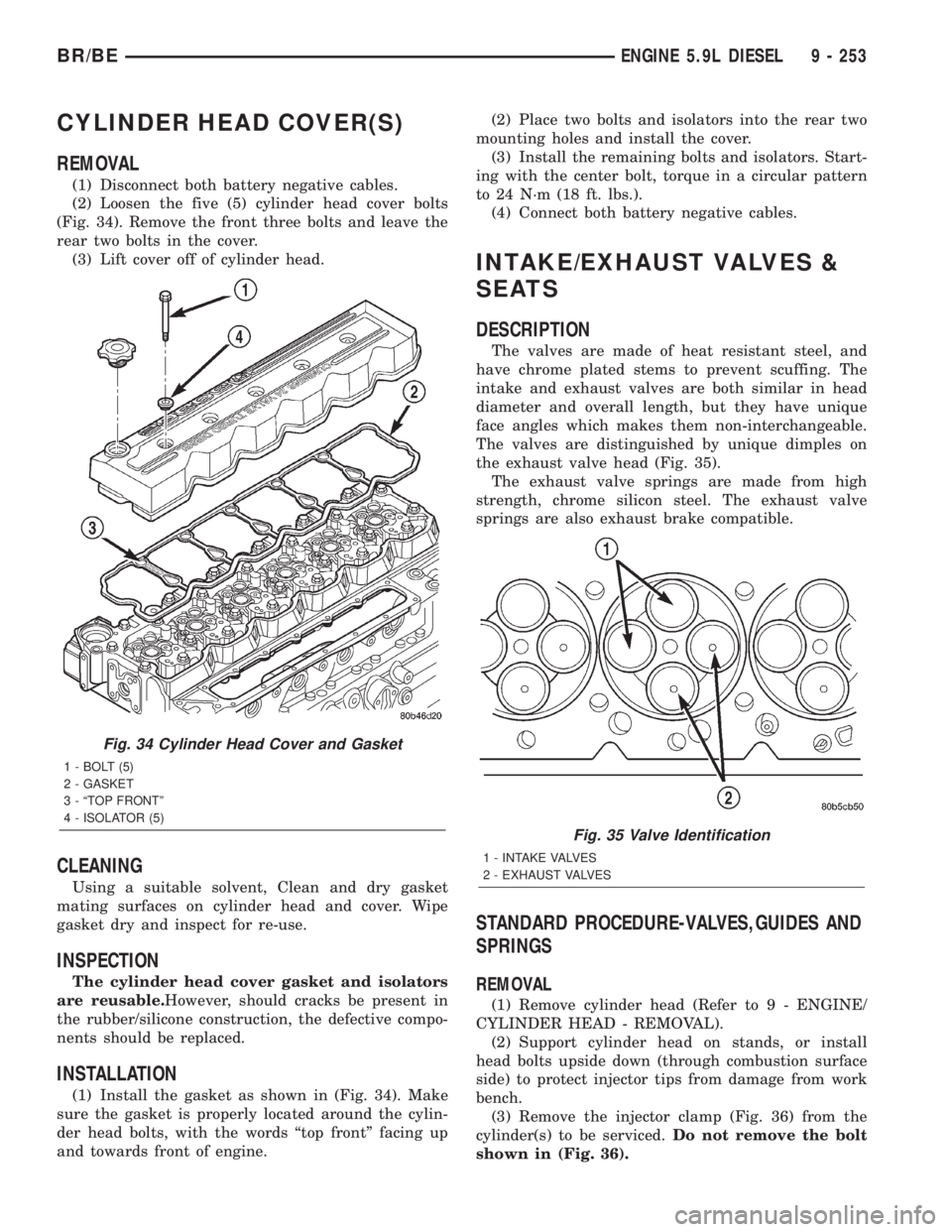
(1) Disconnect both battery negative cables.
(2) Loosen the five (5) cylinder head cover bolts
(Fig. 34). Remove the front three bolts and leave the
rear two bolts in the cover.
(3) Lift cover off of cylinder head.
CLEANING
Using a suitable solvent, Clean and dry gasket
mating surfaces on cylinder head and cover. Wipe
gasket dry and inspect for re-use.
INSPECTION
The cylinder head cover gasket and isolators
are reusable.However, should cracks be present in
the rubber/silicone construction, the defective compo-
nents should be replaced.
INSTALLATION
(1) Install the gasket as shown in (Fig. 34). Make
sure the gasket is properly located around the cylin-
der head bolts, with the words ªtop frontº facing up
and towards front of engine.(2) Place two bolts and isolators into the rear two
mounting holes and install the cover.
(3) Install the remaining bolts and isolators. Start-
ing with the center bolt, torque in a circular pattern
to 24 N´m (18 ft. lbs.).
(4) Connect both battery negative cables.
INTAKE/EXHAUST VALVES &
SEATS
DESCRIPTION
The valves are made of heat resistant steel, and
have chrome plated stems to prevent scuffing. The
intake and exhaust valves are both similar in head
diameter and overall length, but they have unique
face angles which makes them non-interchangeable.
The valves are distinguished by unique dimples on
the exhaust valve head (Fig. 35).
The exhaust valve springs are made from high
strength, chrome silicon steel. The exhaust valve
springs are also exhaust brake compatible.
STANDARD PROCEDURE-VALVES,GUIDES AND
SPRINGS
REMOVAL
(1) Remove cylinder head (Refer to 9 - ENGINE/
CYLINDER HEAD - REMOVAL).
(2) Support cylinder head on stands, or install
head bolts upside down (through combustion surface
side) to protect injector tips from damage from work
bench.
(3) Remove the injector clamp (Fig. 36) from the
cylinder(s) to be serviced.Do not remove the bolt
shown in (Fig. 36).
Fig. 34 Cylinder Head Cover and Gasket
1 - BOLT (5)
2 - GASKET
3 - ªTOP FRONTº
4 - ISOLATOR (5)
Fig. 35 Valve Identification
1 - INTAKE VALVES
2 - EXHAUST VALVES
BR/BEENGINE 5.9L DIESEL 9 - 253