2001 DODGE RAM fuel filter
[x] Cancel search: fuel filterPage 38 of 2889

26,250 Miles (42 000 km)
²Change engine oil and filter.
²Drain crankcase breather canister (if equipped).
30,000 Miles (48 000 km)
²Change engine oil and filter.
²Drain crankcase breather canister (if equipped).
²Inspect fan hub.
²Inspect damper.
²Inspect water pump weep hole for blockage.
²Replace fuel filter and clean water in fuel sen-
sor.
²Drain and refill automatic transmission fluid.
Replace filter and adjust bands.
²Change rear axle fluid.
²Change front axle fluid (4x4).
²Inspect front wheel bearings. Clean and repack,
if required (4x2).
²Inspect brake linings.
33,700 Miles (54 000 km)
²Change engine oil and filter.
²Drain crankcase breather canister (if equipped).
37,500 Miles (60 000 km)
²Change engine oil and filter.
²Drain crankcase breather canister (if equipped).
²Replace fuel filter and clean water in fuel sen-
sor.
41,250 Miles (66 000 km)
²Change engine oil and filter.
²Drain crankcase breather canister (if equipped).
45,000 Miles (72 000 km)
²Change engine oil and filter.
²Drain crankcase breather canister (if equipped).
²Inspect drive belts, replace as necessary.
²Inspect water pump weep hole for blockage.
²Replace fuel filter and clean water in fuel sen-
sor.
²Drain and refill automatic transmission fluid.
Replace filter and adjust bands.
²Drain and refill transfer case fluid.
²Change rear axle fluid.
²Change front axle fluid (4x4).
²Inspect brake linings.
48,750 Miles (78,000 km)
²Change engine oil and filter.
²Drain crankcase breather canister (if equipped).
52,500 Miles (84 000 km)
²Change engine oil and filter.
²Drain crankcase breather canister (if equipped).
²Replace fuel filter and clean water in fuel sen-
sor.
56,250 Miles (90 000 km)
²Change engine oil and filter.
²Drain crankcase breather canister (if equipped).
60,000 Miles (96 000 km)
²Change engine oil and filter.
²Drain crankcase breather canister (if equipped).
²Inspect fan hub.
²Inspect damper.
²Inspect water pump weep hole for blockage.
²Replace fuel filter and clean water in fuel sen-
sor.
²Drain and refill automatic transmission fluid.
Replace filter and adjust bands.
²Change rear axle fluid.
²Change front axle fluid (4x4).
²Inspect front wheel bearings. Clean and repack
if required (4x2).
²Inspect brake linings.
²Flush and replace engine coolant.
63,750 Miles (102 000 km)
²Change engine oil and filter.
²Drain crankcase breather canister (if equipped).
67,500 Miles (108 000 km)
²Change engine oil and filter.
²Drain crankcase breather canister (if equipped).
²Inspect drive belts, replace as necessary.
²Replace fuel filter and clean water in fuel sen-
sor.
71,250 Miles (114 000 km)
²Change engine oil and filter.
²Drain crankcase breather canister (if equipped).
75,000 Miles (120 000 km)
²Change engine oil and filter.
²Drain crankcase breather canister (if equipped).
²Inspect water pump weep hole for blockage.
²Replace fuel filter and clean water in fuel sen-
sor.
²Drain and refill automatic transmission fluid.
Replace filter and adjust bands.
²Change rear axle fluid.
²Change front axle fluid (4x4).
²Inspect brake linings.
78,750 Miles (126 000 km)
²Change engine oil and filter.
²Drain crankcase breather canister (if equipped).
82,500 Miles (132 000 km)
²Change engine oil and filter.
²Drain crankcase breather canister (if equipped).
²Replace fuel filter and clean water in fuel sen-
sor.
BR/BELUBRICATION & MAINTENANCE 0 - 25
MAINTENANCE SCHEDULES (Continued)
Page 39 of 2889

86,250 Miles (138 000 km)
²Change engine oil and filter.
²Drain crankcase breather canister (if equipped).
90,000 Miles (144 000 km)
²Change engine oil and filter.
²Drain crankcase breather canister (if equipped).
²Inspect drive belts, replace as necessary.
²Inspect fan hub.
²Inspect damper.
²Inspect water pump weep hole for blockage.
²
Replace fuel filter and clean water in fuel sensor.
²Drain and refill automatic transmission fluid.
Replace filter and adjust bands.
²Drain and refill transfer case fluid.
²Change rear axle fluid.
²Change front axle fluid (4x4).
²Inspect front wheel bearings. Clean and repack
if required (4x2).
²Inspect brake linings.
93,750 Miles (150 000 km)
²Change engine oil and filter.
²Drain crankcase breather canister (if equipped).
97,500 Miles (156 000 km)
²Change engine oil and filter.
²Drain crankcase breather canister (if equipped).
²Flush and replace engine coolant.
²Replace fuel filter and clean water in fuel sen-
sor.
²Adjust rear brakes.
101,250 Miles (162 000 km)
²Change engine oil and filter.
²Drain crankcase breather canister (if equipped).
105,000 Miles (168 000 km)
²Change engine oil and filter.
²Drain crankcase breather canister (if equipped).
²Inspect water pump weep hole for blockage.
²Replace fuel filter and clean water in fuel sen-
sor.
²Drain and refill automatic transmission fluid.
Replace filter and adjust bands.
²Change rear axle fluid.
²Change front axle fluid (4x4).
²Inspect brake linings.
108,750 Miles (174 000 km)
²Change engine oil and filter.
²Drain crankcase breather canister (if equipped).
112,500 Miles (180 000 km)
²Change engine oil and filter.
²Drain crankcase breather canister (if equipped).
²Inspect drive belts, replace as necessary.²
Replace fuel filter and clean water in fuel sensor.
116,250 Miles (186 000 km)
²Change engine oil and filter.
²Drain crankcase breather canister (if equipped).
120,000 Miles (192 000 km)
²Change engine oil and filter.
²Drain crankcase breather canister (if equipped).
²Inspect fan hub.
²Inspect damper.
²Inspect water pump weep hole for blockage.
²Replace fuel filter and clean water in fuel sen-
sor.
²Drain and refill automatic transmission fluid.
Replace filter and adjust bands.
²Change rear axle fluid.
²Change front axle fluid (4x4).
²Inspect front wheel bearings. Clean and repack
if required (4x2).
²Inspect brake linings.
123,750 Miles (198 000 km)
²Change engine oil and filter.
²Drain crankcase breather canister (if equipped).
127,500 Miles (204 000 km)
²Change engine oil and filter.
²Drain crankcase breather canister (if equipped).
²Replace fuel filter and clean water in fuel sen-
sor.
131,250 Miles (210 000 km)
²Change engine oil and filter.
²Drain crankcase breather canister (if equipped).
135,000 Miles (216 000 km)
²Change engine oil and filter.
²Drain crankcase breather canister (if equipped).
²Clean inside of engine air cleaner element hous-
ing.
²Inspect drive belts, replace as necessary.
²Inspect water pump weep hole for blockage.
²Replace fuel filter and clean water in fuel sen-
sor.
²Adjust valve lash clearance
²Drain and refill automatic transmission fluid.
Replace filter and adjust bands.
²Drain and refill transfer case fluid.
²Change rear axle fluid.
²Change front axle fluid (4x4).
²Inspect brake linings.
²Flush and replace engine coolant.
²Adjust rear brakes
Inspection and service should also be performed
anytime a malfunction is observed or suspected.
0 - 26 LUBRICATION & MAINTENANCEBR/BE
MAINTENANCE SCHEDULES (Continued)
Page 103 of 2889

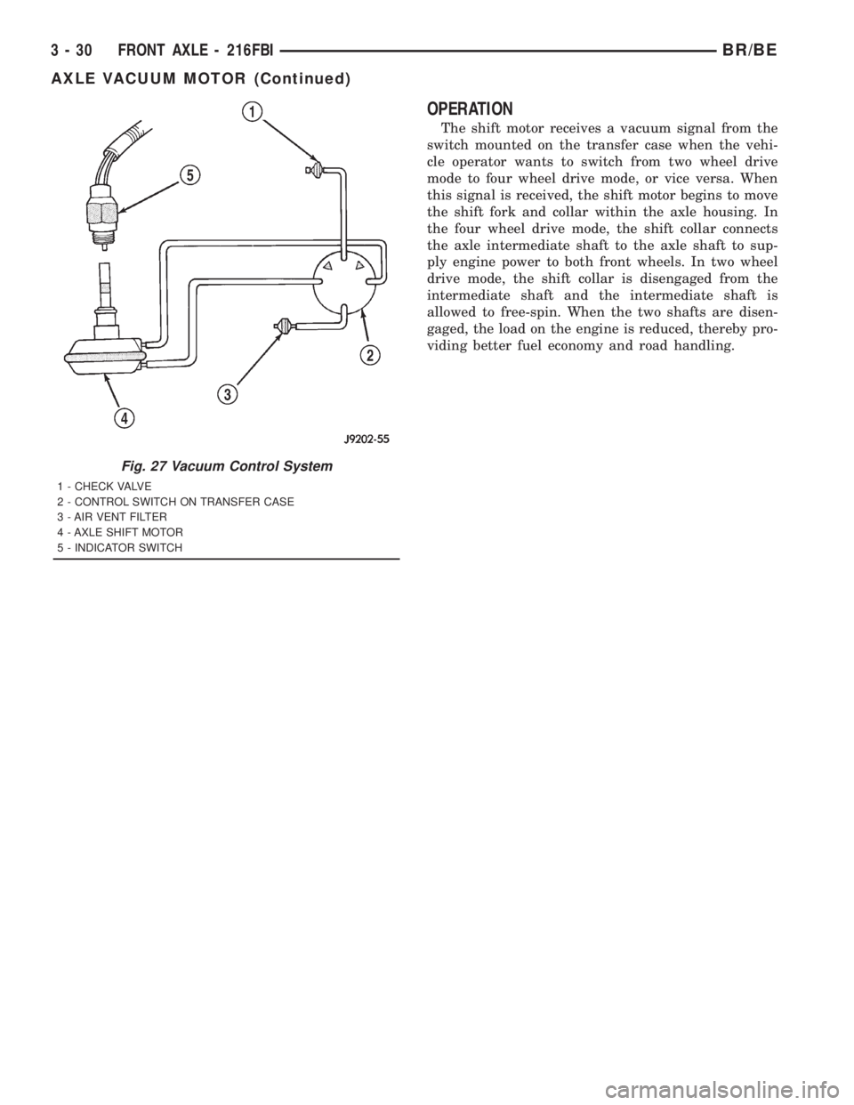
OPERATION
The shift motor receives a vacuum signal from the
switch mounted on the transfer case when the vehi-
cle operator wants to switch from two wheel drive
mode to four wheel drive mode, or vice versa. When
this signal is received, the shift motor begins to move
the shift fork and collar within the axle housing. In
the four wheel drive mode, the shift collar connects
the axle intermediate shaft to the axle shaft to sup-
ply engine power to both front wheels. In two wheel
drive mode, the shift collar is disengaged from the
intermediate shaft and the intermediate shaft is
allowed to free-spin. When the two shafts are disen-
gaged, the load on the engine is reduced, thereby pro-
viding better fuel economy and road handling.
Fig. 27 Vacuum Control System
1 - CHECK VALVE
2 - CONTROL SWITCH ON TRANSFER CASE
3 - AIR VENT FILTER
4 - AXLE SHIFT MOTOR
5 - INDICATOR SWITCH
3 - 30 FRONT AXLE - 216FBIBR/BE
AXLE VACUUM MOTOR (Continued)
Page 135 of 2889

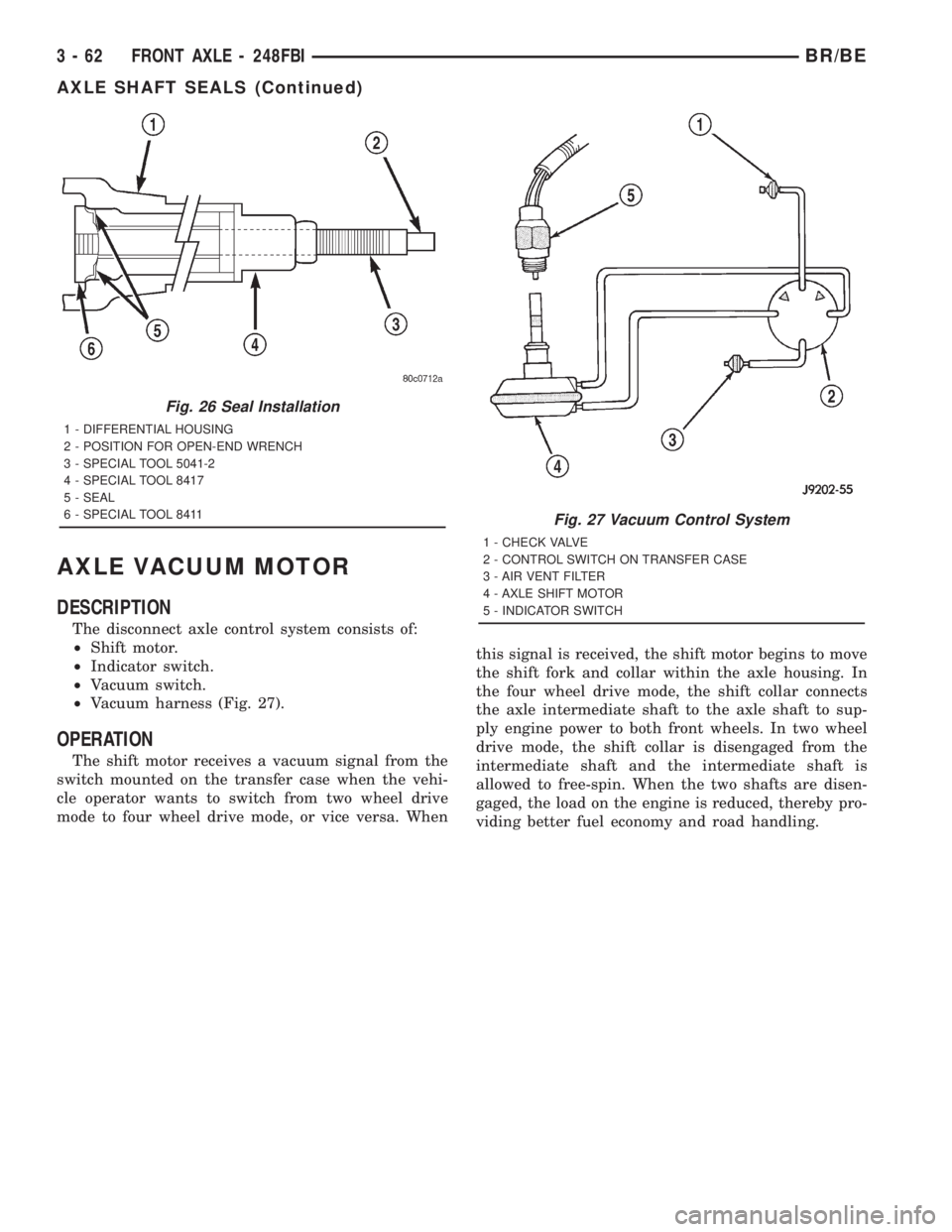
AXLE VACUUM MOTOR
DESCRIPTION
The disconnect axle control system consists of:
²Shift motor.
²Indicator switch.
²Vacuum switch.
²Vacuum harness (Fig. 27).
OPERATION
The shift motor receives a vacuum signal from the
switch mounted on the transfer case when the vehi-
cle operator wants to switch from two wheel drive
mode to four wheel drive mode, or vice versa. Whenthis signal is received, the shift motor begins to move
the shift fork and collar within the axle housing. In
the four wheel drive mode, the shift collar connects
the axle intermediate shaft to the axle shaft to sup-
ply engine power to both front wheels. In two wheel
drive mode, the shift collar is disengaged from the
intermediate shaft and the intermediate shaft is
allowed to free-spin. When the two shafts are disen-
gaged, the load on the engine is reduced, thereby pro-
viding better fuel economy and road handling.
Fig. 26 Seal Installation
1 - DIFFERENTIAL HOUSING
2 - POSITION FOR OPEN-END WRENCH
3 - SPECIAL TOOL 5041-2
4 - SPECIAL TOOL 8417
5 - SEAL
6 - SPECIAL TOOL 8411
Fig. 27 Vacuum Control System
1 - CHECK VALVE
2 - CONTROL SWITCH ON TRANSFER CASE
3 - AIR VENT FILTER
4 - AXLE SHIFT MOTOR
5 - INDICATOR SWITCH
3 - 62 FRONT AXLE - 248FBIBR/BE
AXLE SHAFT SEALS (Continued)
Page 464 of 2889

ENGINE CONTROL MODULE
DESCRIPTION - ECM
The ECM is bolted to the left side of the engine
behind the fuel filter (Fig. 14). It is a separate com-
ponent and can be serviced. The FPCM is internal to
the fuel injection pump (Fig. 15) and cannot be ser-
viced.
OPERATION - ECM
The main functions of the Engine Control Module
(ECM) and Fuel Injection Pump Control Module
(FPCM) are to electrically control the fuel system.
The Powertrain Control Module (PCM)does not
controlthe fuel system.
The ECM can adapt its programming to meet
changing operating conditions.If the ECM has
been replaced, flashed or re-calibrated, the
ECM must learn the Accelerator Pedal Position
Sensor (APPS) idle voltage. Failure to learn
this voltage may result in unnecessary diagnos-
tic trouble codes. Refer to ECM Removal/Instal-
lation for learning procedures.
The ECM receives input signals from various
switches and sensors. Based on these inputs, the
ECM regulates various engine and vehicle operations
through different system components. These compo-
nents are referred to asECM Outputs.The sensors
and switches that provide inputs to the ECM are
consideredECM Inputs.NOTE: ECM Inputs:
²Accelerator Pedal Position Sensor (APPS) Volts
²APPS Idle Validation Switches #1 and #2
²Battery voltage
²Camshaft Position Sensor (CMP)
²CCD bus (+) circuits
²CCD bus (-) circuits
²Crankshaft Position Sensor (CKP)
²Data link connection for DRB scan tool
²(FPCM) Fuel Injection Pump Control Module
²Engine Coolant Temperature (ECT) sensor
²Ground circuits
²Intake manifold Air Temperature (IAT) sensor
²Manifold Air Pressure Sensor (Boost Pressure
Sensor)
²Oil pressure sensor
²PCM
²Power Take Off (PTO)
²Power ground
²Sensor return
²Signal ground
²Water-In-Fuel (WIF) sensor
Fig. 14 Engine Control Module (ECM) Location
1 - ENGINE CONTROL MODULE (ECM)
2 - HEX HEADED BOLT
3 - 50-WAY CONNECTOR
4 - FUEL TRANSFER PUMP
5 - MOUNTING BOLTS (3)
Fig. 15 Fuel Injection Pump Control Module (FPCM)
Location
1 - FPCM ELECTRICAL CONNECTOR
2 - HIGH-PRESSURE FUEL LINES
3 - FITTINGS
4 - FUEL INJECTION PUMP
5 - FPCM
BR/BEELECTRONIC CONTROL MODULES 8E - 13
Page 465 of 2889

NOTE: ECM Outputs:
After inputs are received by the ECM, certain sen-
sors, switches and components are controlled or reg-
ulated by the ECM. These are consideredECM
Outputs.These outputs are for:
²CCD bus (+) circuits
²CCD bus (-) circuits
²CKP and APPS outputs to the PCM
²Data link connection for DRB scan tool
²Five volt sensor supply
²Fuel injection pump
²Fuel injection pump relay
²(FPCM) Fuel Pump Control Module
²Fuel transfer (lift) pump
²Intake manifold air heater relays #1 and #2 con-
trol circuits
²Malfunction indicator lamp (Check engine lamp)
²Oil pressure gauge/warning lamp
²PCM
²Wait-to-start warning lamp
²Water-In-Fuel (WIF) warning lamp
REMOVAL
The ECM is bolted to the engine block behind the
fuel filter (Fig. 16).
(1) Record any Diagnostic Trouble Codes (DTC's)
found in the PCM or ECM.To avoid possible voltage spike damage to either
the Powertrain Control Module (PCM) or ECM, igni-
tion key must be off, and negative battery cables
must be disconnected before unplugging ECM con-
nectors.
(2) Disconnect both negative battery cables at both
batteries.
(3) Remove 50±way electrical connector bolt at
ECM (Fig. 16). Note: Connector bolt is female 4mm
hex head. To remove bolt, use a ball-hex bit or ball-
hex screwdriver such as Snap-Ont4mm SDABM4
(5/32º may also be used). As bolt is being removed,
very carefully remove connector from ECM.
(4) Remove three ECM mounting bolts and remove
ECM from vehicle.
INSTALLATION
Do not apply paint to back of ECM. Poor ground
will result.
(1) Clean ECM mounting points at engine block.
(2) Position ECM to engine block and install 3
mounting bolts. Tighten bolts to 24 N´m (18 ft. lbs.).
(3) Check pin connectors in ECM and 50±way con-
nector for corrosion or damage. Repair as necessary.
(4) Clean pins in 50±way electrical connector with
a quick-dry electrical contact cleaner.
(5) Very carefully install 50±way connector to
ECM. Tighten connector hex bolt.
(6) Install battery cables.
(7)Turn key to ON position. Without starting
engine, slowly press throttle pedal to floor and
then slowly release. This step must be done
(one time) to ensure accelerator pedal position
sensor calibration has been learned by ECM. If
not done, possible DTC's may be set.
(8) Use DRB scan tool to erase any stored compan-
ion DTC's from PCM.
POWERTRAIN CONTROL
MODULE
DESCRIPTION - PCM
The Powertrain Control Module (PCM) is located
in the engine compartment (Fig. 17). The PCM is
referred to as JTEC.
DESCRIPTION - MODES OF OPERATION
As input signals to the Powertrain Control Module
(PCM) change, the PCM adjusts its response to the
output devices. For example, the PCM must calculate
different injector pulse width and ignition timing for
idle than it does for wide open throttle (WOT).
The PCM will operate in two different modes:
Open Loop and Closed Loop.
Fig. 16 Engine Control Module (ECM) Location and
Mounting
1 - ENGINE CONTROL MODULE (ECM)
2 - HEX HEADED BOLT
3 - 50-WAY CONNECTOR
4 - FUEL TRANSFER PUMP
5 - MOUNTING BOLTS (3)
8E - 14 ELECTRONIC CONTROL MODULESBR/BE
ENGINE CONTROL MODULE (Continued)
Page 596 of 2889

OPERATION
The water-in-fuel indicator gives an indication to
the vehicle operator when the water accumulated in
the diesel engine fuel filter/separator filter bowl
requires draining. This indicator is controlled by a
transistor on the instrument cluster circuit board
based upon cluster programming and electronic mes-
sages received by the cluster from the Engine Control
Module (ECM) over the Chrysler Collision Detection
(CCD) data bus. The water-in-fuel indicator Light
Emitting Diode (LED) receives battery current on the
instrument cluster electronic circuit board through
the fused ignition switch output (st-run) circuit
whenever the ignition switch is in the On or Start
positions; therefore, the indicator will always be off
when the ignition switch is in any position except On
or Start. The LED only illuminates when it is
switched to ground by the instrument cluster transis-
tor. The instrument cluster will turn on the water-in-
fuel indicator for the following reasons:
²Bulb Test- Each time the ignition switch is
turned to the On position the indicator is illuminated
for about two seconds as a bulb test.
²Water-In-Fuel Lamp-On Message- Each time
the cluster receives a water-in-fuel lamp-on messagefrom the ECM, the indicator will be illuminated. The
indicator remains illuminated until the cluster
receives a water-in-fuel lamp-off message from the
ECM or until the ignition switch is turned to the Off
position, whichever occurs first.
²Actuator Test- Each time the cluster is put
through the actuator test, the indicator will be
turned on during the bulb check portion of the test to
confirm the functionality of the LED and the cluster
control circuitry.
The ECM continually monitors the water-in-fuel
sensor, then sends the proper messages to the instru-
ment cluster. For further diagnosis of the water-in-
fuel indicator or the instrument cluster circuitry that
controls the indicator, (Refer to 8 - ELECTRICAL/IN-
STRUMENT CLUSTER - DIAGNOSIS AND TEST-
ING). For proper diagnosis of the water-in-fuel
sensor, the ECM, the CCD data bus, or the message
inputs to the instrument cluster that control the
water-in-fuel indicator, a DRBIIItscan tool is
required. Refer to the appropriate diagnostic
information.
BR/BEINSTRUMENT CLUSTER 8J - 37
WATER-IN-FUEL INDICATOR (Continued)
Page 1094 of 2889

Connector Name/Number Color Location Fig.
Cummins Bus (-) Left Front of Engine 10
Cup Holder Lamp Center of Instrument Panel 23,26
Data Link Connector BK Left Bottom of Instrument Panel 23,24
Day/Night Mirror BK Day/Night Mirror N/S
Daytime Running Lamp Module BK Left Fender Side Shield 14
Dome Lamp Rear of Cab 18
Driver Airbag BK Steering Wheel N/S
Driver Door Arm/Disarm Switch BK In Door 19
Driver Door Jamb Switch NAT Door Jamb 19
Driver Door Lock Motor BK In Door 19
Driver Door Window/Lock Switch BL In Door 19
Driver Heated Seat Module BL Under Seat N/S
Driver Heated Seat Switch RD Center of Instrument Panel N/S
Driver Lumbar Motor Under Seat N/S
Driver Power Seat Front Vertical Motor BK Under Seat N/S
Driver Power Seat Horizontal Motor BK Under Seat N/S
Driver Power Seat Rear Vertical Motor Under Seat N/S
Driver Power Seat Switch At Seat N/S
Driver Power Window Motor In Door 19
Duty Cycle EVAP/Purge Solenoid BK Right Fender Side Shield 17
Electric Brake Provision Bottom Left of Instrument Panel N/S
Engine Control Module (Diesel) Left Side Engine 12
Engine Coolant Temperature Sensor (Diesel) BK Left Front of Cylinder Head
(Diesel)10
Engine Coolant Temperature Sensor (Gas) BK On Thermostat Housing 3,6
Engine Oil Pressure Sensor (V6, V8) BK Near Distributor 3
Engine Oil Pressure Sensor (V10) Near Oil Filter 6
Engine Oil Pressure Sensor (Diesel) Left Side of Engine 12
Fuel Heater (Diesel) Left Side of Engine 10
Fuel Injection Pump (Diesel) Left Side of Engine, Below ECM 10
Fuel Injector No.1 BK At Fuel Injector 4,5
Fuel Injector No. 2 BK At Fuel Injector 4,5,6
Fuel Injector No. 3 BK At Fuel Injector 4,5,6
Fuel Injector No. 4 BK At Fuel Injector 4,5,6
Fuel Injector No. 5 BK At Fuel Injector 4,5,6
Fuel Injector No. 6 BK At Fuel Injector 4,5,6
Fuel Injector No. 7 BK At Fuel Injector 4,6
Fuel Injector No. 8 BK At Fuel Injector 4,6
Fuel Injector No. 9 BK At Fuel Injector 6
Fuel Injector No. 10 BK At Fuel Injector 6
Fuel Pump Module LTGY At Frame Rail 22
Fuel Transfer Pump (Diesel) Left Rear of Engine Bottom of
Pump10
BR/BE8W-90 CONNECTOR/GROUND LOCATIONS 8W - 90 - 3
CONNECTOR/GROUND LOCATIONS (Continued)