2001 DODGE RAM brake pads
[x] Cancel search: brake padsPage 299 of 2889
(3) Lubricate adjuster screw socket, nut, button
and screw thread surfaces with grease or Lubriplate.
(4) Install parking brake lever to the secondary
shoe and install retaining clip.
(5) Install primary shoe on support plate. Secure
shoe with new spring retainers and pin.
(6) Install spring on parking brake strut and
engage strut in primary.
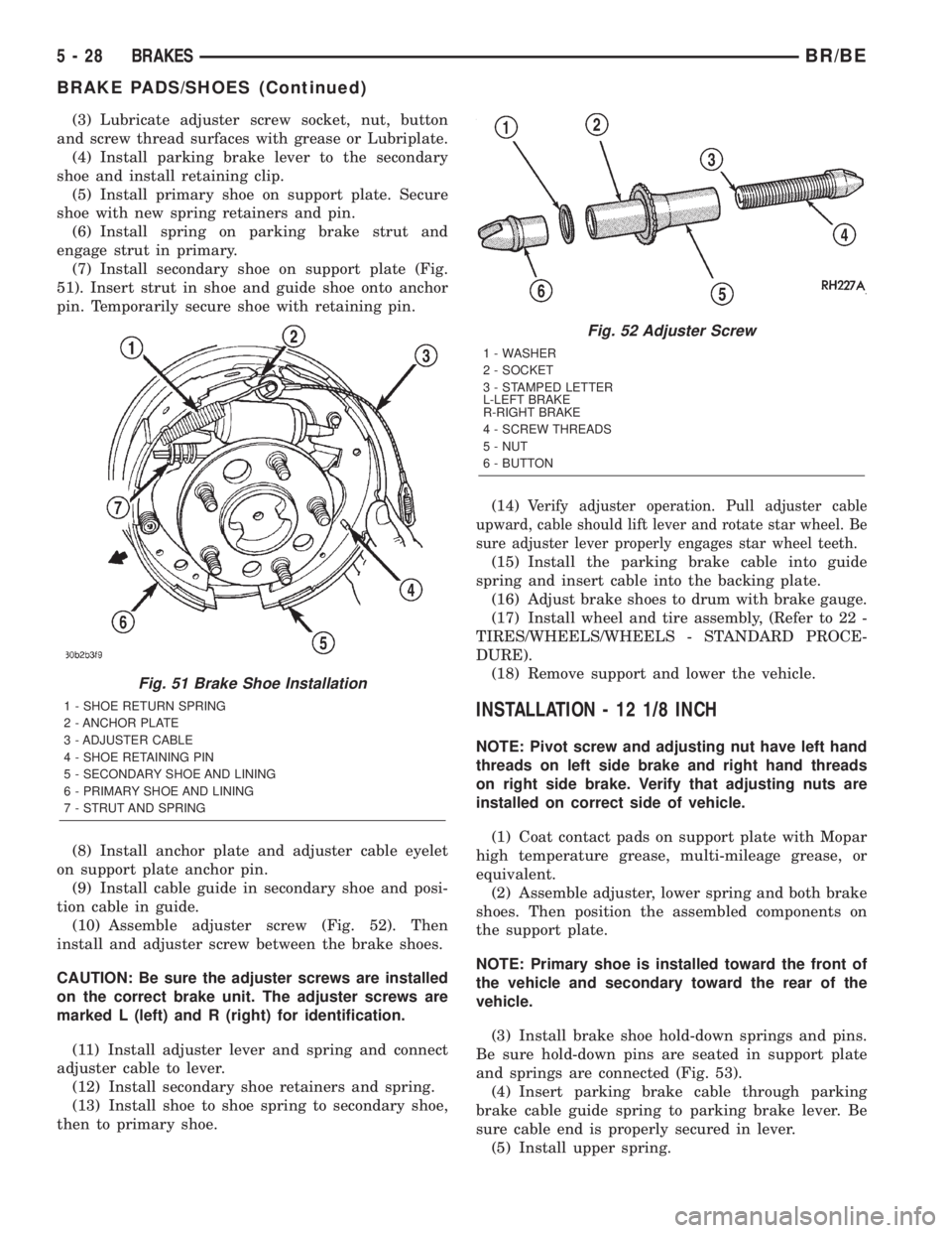
(7) Install secondary shoe on support plate (Fig.
51). Insert strut in shoe and guide shoe onto anchor
pin. Temporarily secure shoe with retaining pin.
(8) Install anchor plate and adjuster cable eyelet
on support plate anchor pin.
(9) Install cable guide in secondary shoe and posi-
tion cable in guide.
(10) Assemble adjuster screw (Fig. 52). Then
install and adjuster screw between the brake shoes.
CAUTION: Be sure the adjuster screws are installed
on the correct brake unit. The adjuster screws are
marked L (left) and R (right) for identification.
(11) Install adjuster lever and spring and connect
adjuster cable to lever.
(12) Install secondary shoe retainers and spring.
(13) Install shoe to shoe spring to secondary shoe,
then to primary shoe.(14)
Verify adjuster operation. Pull adjuster cable
upward, cable should lift lever and rotate star wheel. Be
sure adjuster lever properly engages star wheel teeth.
(15) Install the parking brake cable into guide
spring and insert cable into the backing plate.
(16) Adjust brake shoes to drum with brake gauge.
(17) Install wheel and tire assembly, (Refer to 22 -
TIRES/WHEELS/WHEELS - STANDARD PROCE-
DURE).
(18) Remove support and lower the vehicle.
INSTALLATION - 12 1/8 INCH
NOTE: Pivot screw and adjusting nut have left hand
threads on left side brake and right hand threads
on right side brake. Verify that adjusting nuts are
installed on correct side of vehicle.
(1) Coat contact pads on support plate with Mopar
high temperature grease, multi-mileage grease, or
equivalent.
(2) Assemble adjuster, lower spring and both brake
shoes. Then position the assembled components on
the support plate.
NOTE: Primary shoe is installed toward the front of
the vehicle and secondary toward the rear of the
vehicle.
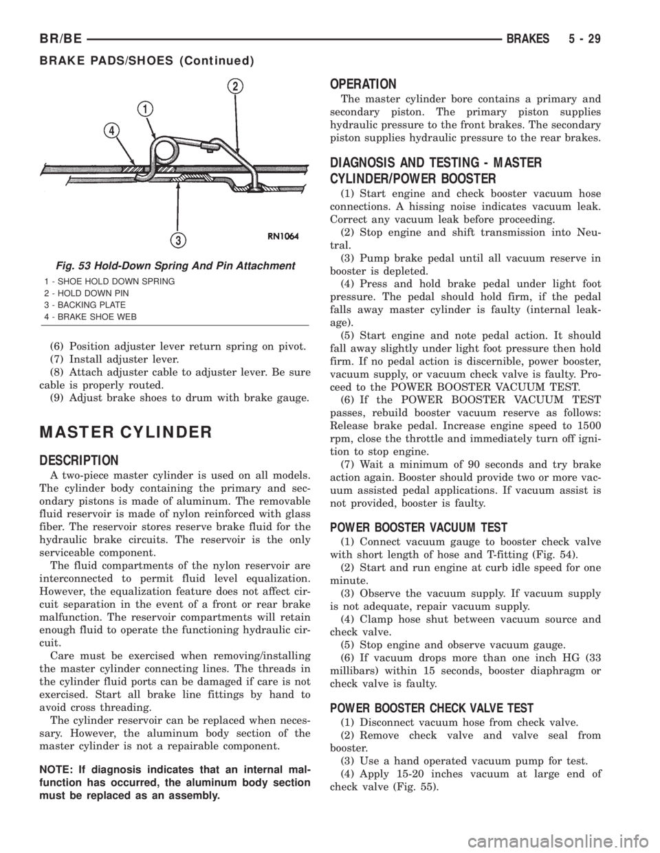
(3) Install brake shoe hold-down springs and pins.
Be sure hold-down pins are seated in support plate
and springs are connected (Fig. 53).
(4) Insert parking brake cable through parking
brake cable guide spring to parking brake lever. Be
sure cable end is properly secured in lever.
(5) Install upper spring.
Fig. 51 Brake Shoe Installation
1 - SHOE RETURN SPRING
2 - ANCHOR PLATE
3 - ADJUSTER CABLE
4 - SHOE RETAINING PIN
5 - SECONDARY SHOE AND LINING
6 - PRIMARY SHOE AND LINING
7 - STRUT AND SPRING
Fig. 52 Adjuster Screw
1 - WASHER
2 - SOCKET
3 - STAMPED LETTER
L-LEFT BRAKE
R-RIGHT BRAKE
4 - SCREW THREADS
5 - NUT
6 - BUTTON
5 - 28 BRAKESBR/BE
BRAKE PADS/SHOES (Continued)
Page 300 of 2889
(6) Position adjuster lever return spring on pivot.
(7) Install adjuster lever.
(8) Attach adjuster cable to adjuster lever. Be sure
cable is properly routed.
(9) Adjust brake shoes to drum with brake gauge.
MASTER CYLINDER
DESCRIPTION
A two-piece master cylinder is used on all models.
The cylinder body containing the primary and sec-
ondary pistons is made of aluminum. The removable
fluid reservoir is made of nylon reinforced with glass
fiber. The reservoir stores reserve brake fluid for the
hydraulic brake circuits. The reservoir is the only
serviceable component.
The fluid compartments of the nylon reservoir are
interconnected to permit fluid level equalization.
However, the equalization feature does not affect cir-
cuit separation in the event of a front or rear brake
malfunction. The reservoir compartments will retain
enough fluid to operate the functioning hydraulic cir-
cuit.
Care must be exercised when removing/installing
the master cylinder connecting lines. The threads in
the cylinder fluid ports can be damaged if care is not
exercised. Start all brake line fittings by hand to
avoid cross threading.
The cylinder reservoir can be replaced when neces-
sary. However, the aluminum body section of the
master cylinder is not a repairable component.
NOTE: If diagnosis indicates that an internal mal-
function has occurred, the aluminum body section
must be replaced as an assembly.
OPERATION
The master cylinder bore contains a primary and
secondary piston. The primary piston supplies
hydraulic pressure to the front brakes. The secondary
piston supplies hydraulic pressure to the rear brakes.
DIAGNOSIS AND TESTING - MASTER
CYLINDER/POWER BOOSTER
(1) Start engine and check booster vacuum hose
connections. A hissing noise indicates vacuum leak.
Correct any vacuum leak before proceeding.
(2) Stop engine and shift transmission into Neu-
tral.
(3) Pump brake pedal until all vacuum reserve in
booster is depleted.
(4) Press and hold brake pedal under light foot
pressure. The pedal should hold firm, if the pedal
falls away master cylinder is faulty (internal leak-
age).
(5) Start engine and note pedal action. It should
fall away slightly under light foot pressure then hold
firm. If no pedal action is discernible, power booster,
vacuum supply, or vacuum check valve is faulty. Pro-
ceed to the POWER BOOSTER VACUUM TEST.
(6) If the POWER BOOSTER VACUUM TEST
passes, rebuild booster vacuum reserve as follows:
Release brake pedal. Increase engine speed to 1500
rpm, close the throttle and immediately turn off igni-
tion to stop engine.
(7) Wait a minimum of 90 seconds and try brake
action again. Booster should provide two or more vac-
uum assisted pedal applications. If vacuum assist is
not provided, booster is faulty.
POWER BOOSTER VACUUM TEST
(1) Connect vacuum gauge to booster check valve
with short length of hose and T-fitting (Fig. 54).
(2) Start and run engine at curb idle speed for one
minute.
(3) Observe the vacuum supply. If vacuum supply
is not adequate, repair vacuum supply.
(4) Clamp hose shut between vacuum source and
check valve.
(5) Stop engine and observe vacuum gauge.
(6) If vacuum drops more than one inch HG (33
millibars) within 15 seconds, booster diaphragm or
check valve is faulty.
POWER BOOSTER CHECK VALVE TEST
(1) Disconnect vacuum hose from check valve.
(2) Remove check valve and valve seal from
booster.
(3) Use a hand operated vacuum pump for test.
(4) Apply 15-20 inches vacuum at large end of
check valve (Fig. 55).
Fig. 53 Hold-Down Spring And Pin Attachment
1 - SHOE HOLD DOWN SPRING
2 - HOLD DOWN PIN
3 - BACKING PLATE
4 - BRAKE SHOE WEB
BR/BEBRAKES 5 - 29
BRAKE PADS/SHOES (Continued)
Page 304 of 2889

The drum forces both brake shoes to move in the
same direction of rotation. Servo action begins with
the primary brake shoe which begins to wedge (or
wrap) itself against the rotating drum surface. This
force is transmitted equally to the secondary brake
shoe through the adjuster screw and anchor pin. The
net result is that each shoe helps the other exert
extra force against the drum. It is servo action that
creates the wedging (or wrap) effect which produces
increased force on the drum braking surface.
All drum brake assemblies are equipped with a self
adjusting mechanism. The components forming the
mechanism consist of the: adjuster screw, adjuster
lever, actuating lever (11 inch brake), lever return
spring and the adjuster lever spring. The adjuster
lever on the 12 inch brake, is also equipped with a
lever and tension spring.
The adjuster mechanism performs two important
functions. First, is in maintaining proper brake shoe
operating clearance. And second, is to maintain brake
pedal height. The mechanism does so, by adjusting
the shoes in small increments to compensate for lin-
ing wear. The adjustment process is continuous
throughout the useful life of the brake lining.
The adjuster components are all connected to the
secondary brake shoes. Actual adjustment only
occurs during reverse brake stops. Secondary brake
shoe movement (during reverse stops), is what acti-
vates the adjuster components.
In operation, secondary shoe movement causes the
adjuster lever spring to exert pull on the lever. This
pivots the lever away from the adjuster screw teeth.
When the stop is completed and the brakes released,
the adjuster lever pivots back to a normal position. It
is during this return movement of the lever when
adjustment occurs. At this point, the lever comes
back into contact with the adjuster screw teeth as it
moves upward. The lever will then rotate the
adjuster screw one or two teeth as needed for adjust-
ment.
NOTE: The adjustment process requires a complete
stop to actually occur. Rolling stops will NOT acti-
vate the adjuster components. In addition, the
adjuster screws are left and right hand parts and
must NOT be interchanged.
DIAGNOSIS AND TESTING - BRAKE DRUM
The maximum allowable diameter of the drum
braking surface is indicated on the drum outer edge.
Generally, a drum can be machined to a maximum of
1.52 mm (0.060 in.) oversize. Always replace the
drum if machining would cause drum diameter to
exceed the size limit indicated on the drum.
BRAKE DRUM RUNOUT
Measure drum diameter and runout with an accu-
rate gauge. The most accurate method of measure-
ment involves mounting the drum in a brake lathe
and checking variation and runout with a dial indi-
cator.
Variations in drum diameter should not exceed
0.069 mm (0.0028 in.). Drum runout should not
exceed 0.18 mm (0.007 in.) out of round. Machine the
drum if runout or variation exceed these values.
Replace the drum if machining causes the drum to
exceed the maximum allowable diameter.
STANDARD PROCEDURE - BRAKE DRUM
MACHINING
The brake drums can be machined on a drum lathe
when necessary. Initial machining cuts should be lim-
ited to 0.12 - 0.20 mm (0.005 - 0.008 in.) at a time as
heavier feed rates can produce taper and surface
variation. Final finish cuts of 0.025 to 0.038 mm
(0.001 to 0.0015 in.) are recommended and will gen-
erally provide the best surface finish.
Be sure the drum is securely mounted in the lathe
before machining operations. A damper strap should
always be used around the drum to reduce vibration
and avoid chatter marks.
The maximum allowable diameter of the drum
braking surface is stamped or cast into the drum
outer edge.
CAUTION: Replace the drum if machining will cause
the drum to exceed the maximum allowable diame-
ter.
CLEANING
Clean the individual brake components, including
the support plate and wheel cylinder exterior, with a
water dampened cloth or with brake cleaner. Do not
use any other cleaning agents. Remove light rust and
scale from the brake shoe contact pads on the sup-
port plate with fine sandpaper.
INSPECTION
As a general rule, riveted brake shoes should be
replaced when worn to within 0.78 mm (1/32 in.) of
the rivet heads. Bonded lining should be replaced
when worn to a thickness of 1.6 mm (1/16 in.).
Examine the lining contact pattern to determine if
the shoes are bent or the drum is tapered. The lining
should exhibit contact across its entire width. Shoes
exhibiting contact only on one side should be
replaced and the drum checked for runout or taper.
Inspect the adjuster screw assembly. Replace the
assembly if the star wheel or threads are damaged,
or the components are severely rusted or corroded.
BR/BEBRAKES 5 - 33
DRUM (Continued)
Page 305 of 2889
Discard the brake springs and retainer components
if worn, distorted or collapsed. Also replace the
springs if a brake drag condition had occurred. Over-
heating will distort and weaken the springs.
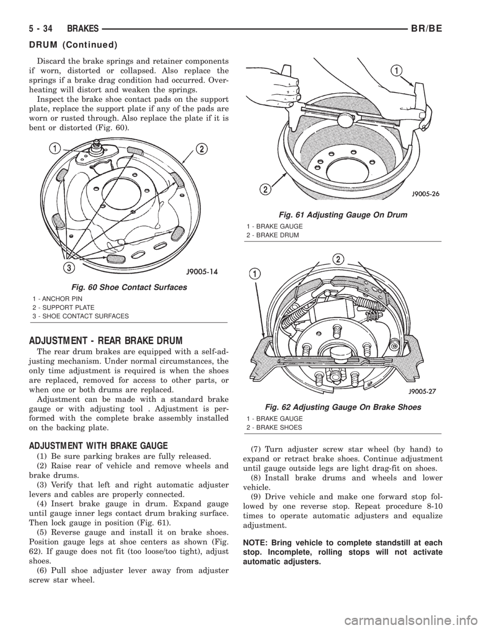
Inspect the brake shoe contact pads on the support
plate, replace the support plate if any of the pads are
worn or rusted through. Also replace the plate if it is
bent or distorted (Fig. 60).
ADJUSTMENT - REAR BRAKE DRUM
The rear drum brakes are equipped with a self-ad-
justing mechanism. Under normal circumstances, the
only time adjustment is required is when the shoes
are replaced, removed for access to other parts, or
when one or both drums are replaced.
Adjustment can be made with a standard brake
gauge or with adjusting tool . Adjustment is per-
formed with the complete brake assembly installed
on the backing plate.
ADJUSTMENT WITH BRAKE GAUGE
(1) Be sure parking brakes are fully released.
(2) Raise rear of vehicle and remove wheels and
brake drums.
(3) Verify that left and right automatic adjuster
levers and cables are properly connected.
(4) Insert brake gauge in drum. Expand gauge
until gauge inner legs contact drum braking surface.
Then lock gauge in position (Fig. 61).
(5) Reverse gauge and install it on brake shoes.
Position gauge legs at shoe centers as shown (Fig.
62). If gauge does not fit (too loose/too tight), adjust
shoes.
(6) Pull shoe adjuster lever away from adjuster
screw star wheel.(7) Turn adjuster screw star wheel (by hand) to
expand or retract brake shoes. Continue adjustment
until gauge outside legs are light drag-fit on shoes.
(8) Install brake drums and wheels and lower
vehicle.
(9) Drive vehicle and make one forward stop fol-
lowed by one reverse stop. Repeat procedure 8-10
times to operate automatic adjusters and equalize
adjustment.
NOTE: Bring vehicle to complete standstill at each
stop. Incomplete, rolling stops will not activate
automatic adjusters.
Fig. 60 Shoe Contact Surfaces
1 - ANCHOR PIN
2 - SUPPORT PLATE
3 - SHOE CONTACT SURFACES
Fig. 61 Adjusting Gauge On Drum
1 - BRAKE GAUGE
2 - BRAKE DRUM
Fig. 62 Adjusting Gauge On Brake Shoes
1 - BRAKE GAUGE
2 - BRAKE SHOES
5 - 34 BRAKESBR/BE
DRUM (Continued)