2001 DODGE RAM diagram
[x] Cancel search: diagramPage 1940 of 2889
AUTOMATIC TRANSMISSION - 44RE
TABLE OF CONTENTS
page page
AUTOMATIC TRANSMISSION - 44RE
DESCRIPTION..........................306
OPERATION............................308
DIAGNOSIS AND TESTING................314
AUTOMATIC TRANSMISSION.............314
PRELIMINARY........................314
ROAD TESTING.......................314
HYDRAULIC PRESSURE TEST...........315
AIR CHECKING TRANSMISSION CLUTCH
AND BAND OPERATION.................318
CONVERTER HOUSING FLUID LEAK......319
DIAGNOSIS CHARTS...................320
STANDARD PROCEDURE.................330
ALUMINUM THREAD REPAIR.............330
REMOVAL.............................330
DISASSEMBLY..........................331
CLEANING.............................336
INSPECTION...........................337
ASSEMBLY............................337
INSTALLATION..........................344
SCHEMATICS AND DIAGRAMS.............345
SPECIFICATIONS........................357
SPECIAL TOOLS........................359
ACCUMULATOR
DESCRIPTION..........................362
OPERATION............................362
INSPECTION...........................363
BANDS
DESCRIPTION..........................363
OPERATION............................364
ADJUSTMENTS.........................364
ELECTRONIC GOVERNOR
DESCRIPTION..........................365
OPERATION............................365
REMOVAL.............................367
INSTALLATION..........................367
EXTENSION HOUSING BUSHING
REMOVAL.............................369
INSTALLATION..........................369
EXTENSION HOUSING SEAL
REMOVAL.............................369
INSTALLATION..........................369
FLUID AND FILTER
DIAGNOSIS AND TESTING................370
EFFECTS OF INCORRECT FLUID LEVEL . . . 370
CAUSES OF BURNT FLUID..............370
FLUID CONTAMINATION................370
STANDARD PROCEDURE.................370
FLUID LEVEL CHECK...................370FLUID AND FILTER REPLACEMENT.......372
TRANSMISSION FILL...................372
FRONT CLUTCH
DESCRIPTION..........................373
OPERATION............................373
DISASSEMBLY..........................373
INSPECTION...........................376
ASSEMBLY............................376
FRONT SERVO
DESCRIPTION..........................377
OPERATION............................377
DISASSEMBLY..........................378
CLEANING.............................378
INSPECTION...........................378
ASSEMBLY............................379
OIL PUMP
DESCRIPTION..........................379
OPERATION............................379
STANDARD PROCEDURE.................379
OIL PUMP VOLUME CHECK..............379
DISASSEMBLY..........................380
CLEANING.............................381
INSPECTION...........................382
ASSEMBLY............................382
OUTPUT SHAFT FRONT BEARING
REMOVAL.............................384
INSTALLATION..........................384
OUTPUT SHAFT REAR BEARING
REMOVAL.............................384
INSTALLATION..........................384
OVERDRIVE CLUTCH
DESCRIPTION..........................385
OPERATION............................385
OVERDRIVE SWITCH
DESCRIPTION..........................385
OPERATION............................385
DIAGNOSIS AND TESTING................386
OVERDRIVE ELECTRICAL CONTROLS.....386
REMOVAL.............................386
INSTALLATION..........................386
OVERDRIVE UNIT
REMOVAL.............................387
DISASSEMBLY..........................387
CLEANING.............................394
INSPECTION...........................394
ASSEMBLY............................395
INSTALLATION..........................404
BR/BEAUTOMATIC TRANSMISSION - 44RE 21 - 305
Page 1955 of 2889
plug threads and tighten plug to 17 N´m (150 in. lbs.)
torque.
(7) Adjust front band.
(8) Lubricate pump seal and converter hub with
transmission fluid or petroleum jelly and install con-
verter.
(9) Install transmission and converter housing
dust shield.
(10) Lower vehicle.
DIAGNOSIS AND TESTING - DIAGNOSIS
CHARTS
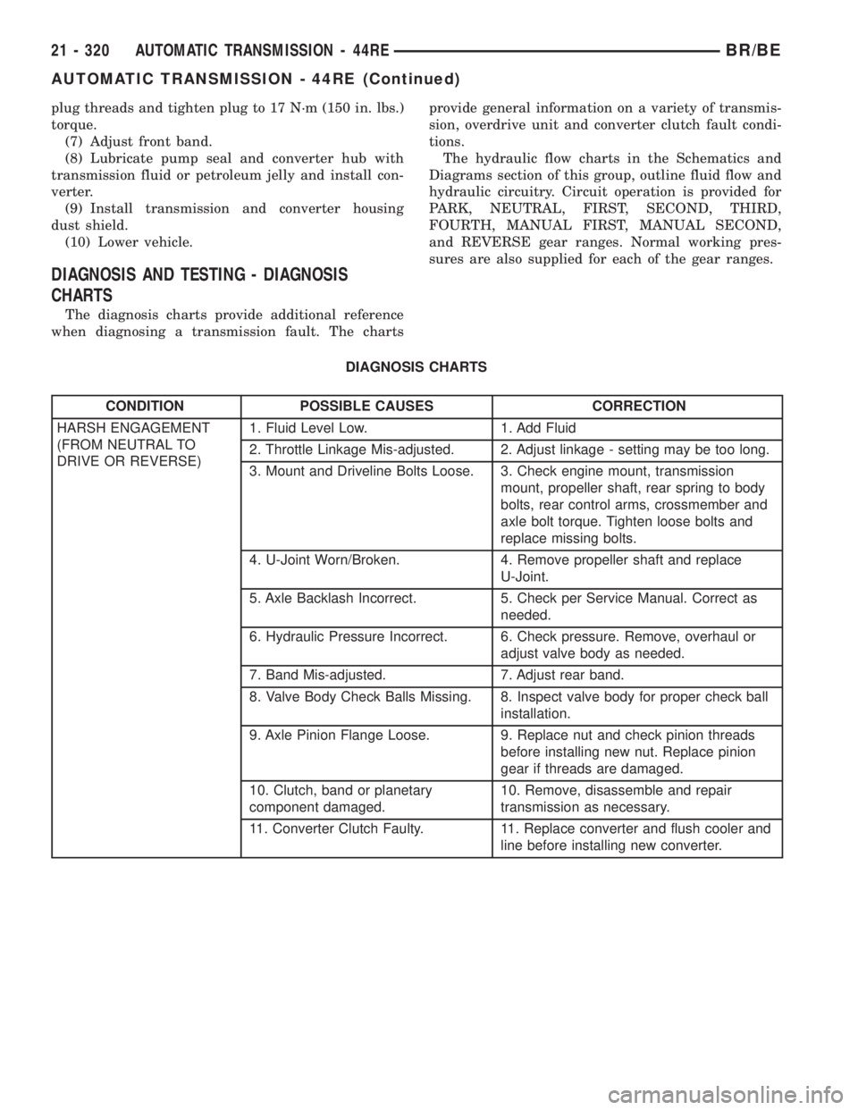
The diagnosis charts provide additional reference
when diagnosing a transmission fault. The chartsprovide general information on a variety of transmis-
sion, overdrive unit and converter clutch fault condi-
tions.
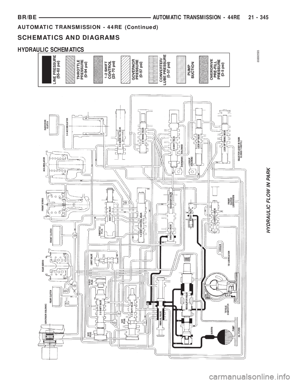
The hydraulic flow charts in the Schematics and
Diagrams section of this group, outline fluid flow and
hydraulic circuitry. Circuit operation is provided for
PARK, NEUTRAL, FIRST, SECOND, THIRD,
FOURTH, MANUAL FIRST, MANUAL SECOND,
and REVERSE gear ranges. Normal working pres-
sures are also supplied for each of the gear ranges.
DIAGNOSIS CHARTS
CONDITION POSSIBLE CAUSES CORRECTION
HARSH ENGAGEMENT
(FROM NEUTRAL TO
DRIVE OR REVERSE)1. Fluid Level Low. 1. Add Fluid
2. Throttle Linkage Mis-adjusted. 2. Adjust linkage - setting may be too long.
3. Mount and Driveline Bolts Loose. 3. Check engine mount, transmission
mount, propeller shaft, rear spring to body
bolts, rear control arms, crossmember and
axle bolt torque. Tighten loose bolts and
replace missing bolts.
4. U-Joint Worn/Broken. 4. Remove propeller shaft and replace
U-Joint.
5. Axle Backlash Incorrect. 5. Check per Service Manual. Correct as
needed.
6. Hydraulic Pressure Incorrect. 6. Check pressure. Remove, overhaul or
adjust valve body as needed.
7. Band Mis-adjusted. 7. Adjust rear band.
8. Valve Body Check Balls Missing. 8. Inspect valve body for proper check ball
installation.
9. Axle Pinion Flange Loose. 9. Replace nut and check pinion threads
before installing new nut. Replace pinion
gear if threads are damaged.
10. Clutch, band or planetary
component damaged.10. Remove, disassemble and repair
transmission as necessary.
11. Converter Clutch Faulty. 11. Replace converter and flush cooler and
line before installing new converter.
21 - 320 AUTOMATIC TRANSMISSION - 44REBR/BE
AUTOMATIC TRANSMISSION - 44RE (Continued)
Page 1980 of 2889
SCHEMATICS AND DIAGRAMS
HYDRAULIC SCHEMATICS
HYDRAULIC FLOW IN PARK
BR/BEAUTOMATIC TRANSMISSION - 44RE 21 - 345
AUTOMATIC TRANSMISSION - 44RE (Continued)
Page 2074 of 2889
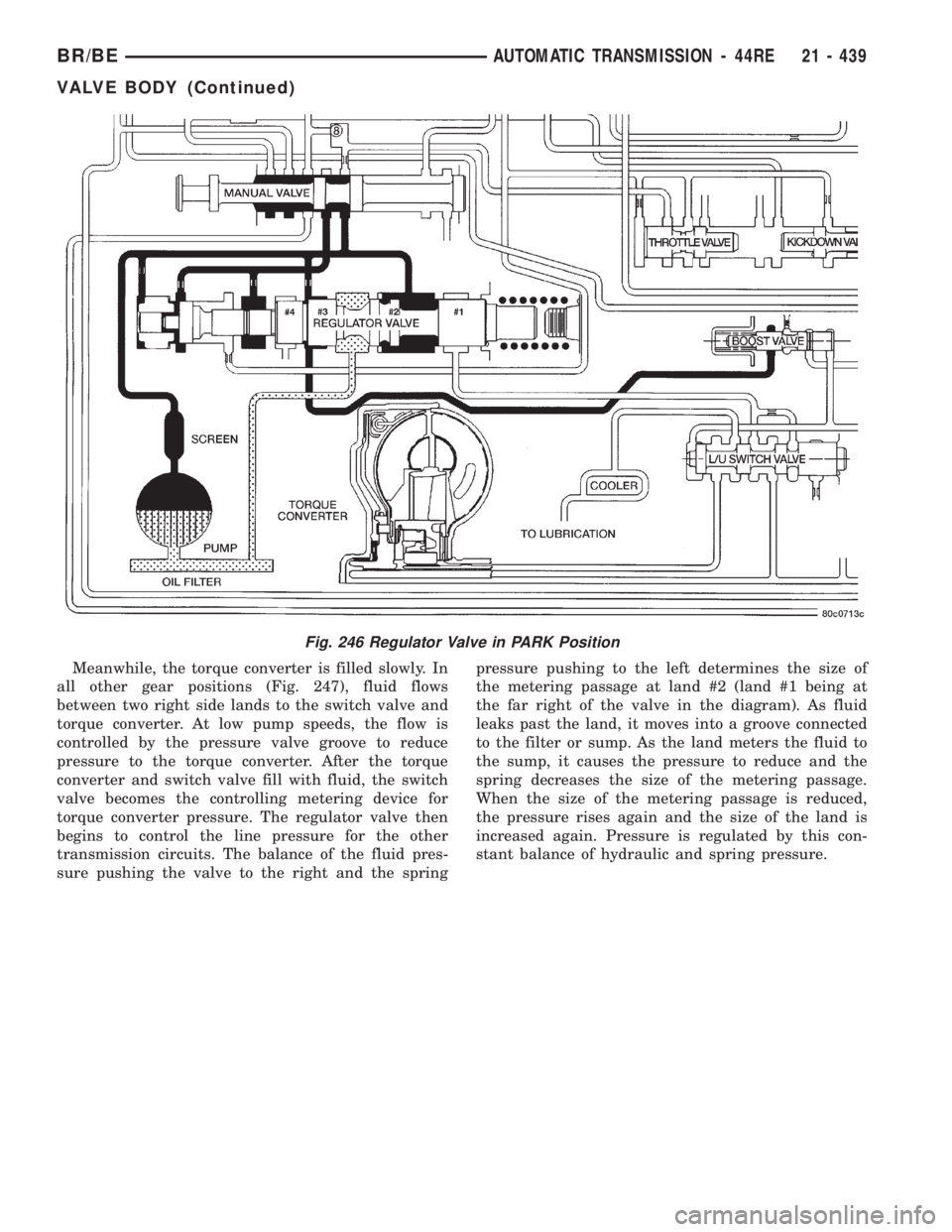
Meanwhile, the torque converter is filled slowly. In
all other gear positions (Fig. 247), fluid flows
between two right side lands to the switch valve and
torque converter. At low pump speeds, the flow is
controlled by the pressure valve groove to reduce
pressure to the torque converter. After the torque
converter and switch valve fill with fluid, the switch
valve becomes the controlling metering device for
torque converter pressure. The regulator valve then
begins to control the line pressure for the other
transmission circuits. The balance of the fluid pres-
sure pushing the valve to the right and the springpressure pushing to the left determines the size of
the metering passage at land #2 (land #1 being at
the far right of the valve in the diagram). As fluid
leaks past the land, it moves into a groove connected
to the filter or sump. As the land meters the fluid to
the sump, it causes the pressure to reduce and the
spring decreases the size of the metering passage.
When the size of the metering passage is reduced,
the pressure rises again and the size of the land is
increased again. Pressure is regulated by this con-
stant balance of hydraulic and spring pressure.
Fig. 246 Regulator Valve in PARK Position
BR/BEAUTOMATIC TRANSMISSION - 44RE 21 - 439
VALVE BODY (Continued)
Page 2112 of 2889
AUTOMATIC TRANSMISSION - 46RE
TABLE OF CONTENTS
page page
AUTOMATIC TRANSMISSION - 46RE
DESCRIPTION..........................478
OPERATION............................480
DIAGNOSIS AND TESTING................486
AUTOMATIC TRANSMISSION.............486
PRELIMINARY........................486
ROAD TESTING.......................486
HYDRAULIC PRESSURE TEST...........487
AIR TESTING TRANSMISSION CLUTCH
AND BAND OPERATION.................490
CONVERTER HOUSING FLUID LEAK......491
DIAGNOSIS CHARTS...................492
STANDARD PROCEDURE.................502
ALUMINUM THREAD REPAIR.............502
REMOVAL.............................502
DISASSEMBLY..........................503
CLEANING.............................509
INSPECTION...........................510
ASSEMBLY............................510
INSTALLATION..........................518
SCHEMATICS AND DIAGRAMS.............520
SPECIFICATIONS........................532
SPECIAL TOOLS........................534
ACCUMULATOR
DESCRIPTION..........................537
OPERATION............................537
INSPECTION...........................538
BANDS
DESCRIPTION..........................538
OPERATION............................539
ADJUSTMENTS.........................539
ELECTRONIC GOVERNOR
DESCRIPTION..........................540
OPERATION............................541
REMOVAL.............................542
INSTALLATION..........................543
EXTENSION HOUSING BUSHING
REMOVAL.............................544
INSTALLATION..........................544
EXTENSION HOUSING SEAL
REMOVAL.............................544
INSTALLATION..........................544
FLUID AND FILTER
DIAGNOSIS AND TESTING................545
EFFECTS OF INCORRECT FLUID LEVEL . . . 545
CAUSES OF BURNT FLUID..............545
FLUID CONTAMINATION................545
STANDARD PROCEDURE.................545
FLUID LEVEL CHECK...................545FLUID AND FILTER REPLACEMENT.......547
TRANSMISSION FILL...................547
FRONT CLUTCH
DESCRIPTION..........................548
OPERATION............................548
DISASSEMBLY..........................549
INSPECTION...........................550
ASSEMBLY............................550
FRONT SERVO
DESCRIPTION..........................551
OPERATION............................552
DISASSEMBLY..........................552
CLEANING.............................552
INSPECTION...........................553
ASSEMBLY............................553
OIL PUMP
DESCRIPTION..........................554
OPERATION............................554
STANDARD PROCEDURE.................554
OIL PUMP VOLUME CHECK..............554
DISASSEMBLY..........................555
CLEANING.............................557
INSPECTION...........................557
ASSEMBLY............................558
OUTPUT SHAFT FRONT BEARING
REMOVAL.............................559
INSTALLATION..........................560
OUTPUT SHAFT REAR BEARING
REMOVAL.............................560
INSTALLATION..........................560
OVERDRIVE CLUTCH
DESCRIPTION..........................560
OPERATION............................560
OVERDRIVE UNIT
REMOVAL.............................560
DISASSEMBLY..........................562
CLEANING.............................568
INSPECTION...........................569
ASSEMBLY............................569
INSTALLATION..........................577
OVERDRIVE SWITCH
DESCRIPTION..........................578
OPERATION............................579
DIAGNOSIS AND TESTING................579
OVERDRIVE ELECTRICAL CONTROLS.....579
REMOVAL.............................579
INSTALLATION..........................579
BR/BEAUTOMATIC TRANSMISSION - 46RE 21 - 477
Page 2127 of 2889
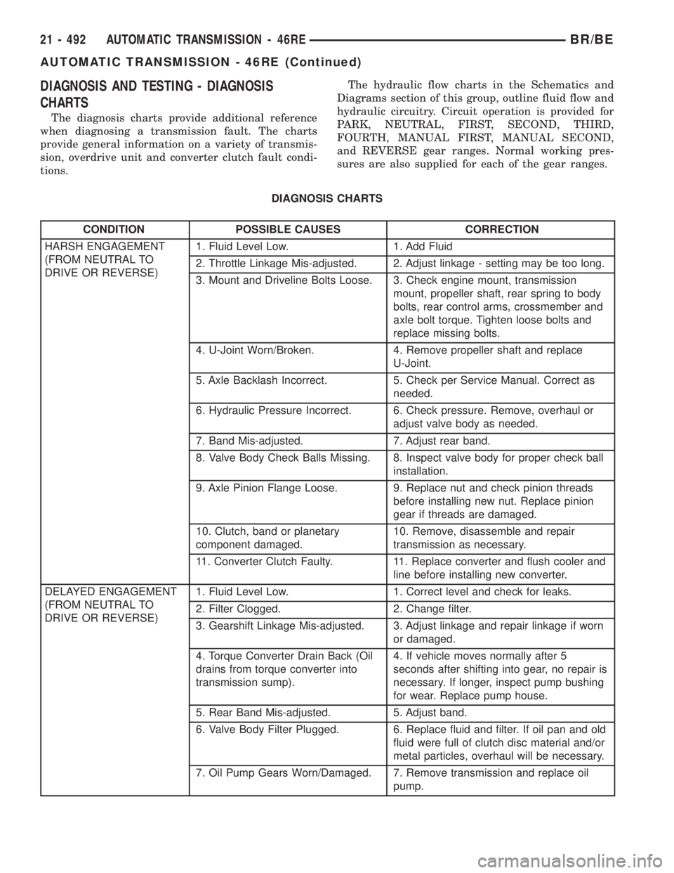
DIAGNOSIS AND TESTING - DIAGNOSIS
CHARTS
The diagnosis charts provide additional reference
when diagnosing a transmission fault. The charts
provide general information on a variety of transmis-
sion, overdrive unit and converter clutch fault condi-
tions.The hydraulic flow charts in the Schematics and
Diagrams section of this group, outline fluid flow and
hydraulic circuitry. Circuit operation is provided for
PARK, NEUTRAL, FIRST, SECOND, THIRD,
FOURTH, MANUAL FIRST, MANUAL SECOND,
and REVERSE gear ranges. Normal working pres-
sures are also supplied for each of the gear ranges.
DIAGNOSIS CHARTS
CONDITION POSSIBLE CAUSES CORRECTION
HARSH ENGAGEMENT
(FROM NEUTRAL TO
DRIVE OR REVERSE)1. Fluid Level Low. 1. Add Fluid
2. Throttle Linkage Mis-adjusted. 2. Adjust linkage - setting may be too long.
3. Mount and Driveline Bolts Loose. 3. Check engine mount, transmission
mount, propeller shaft, rear spring to body
bolts, rear control arms, crossmember and
axle bolt torque. Tighten loose bolts and
replace missing bolts.
4. U-Joint Worn/Broken. 4. Remove propeller shaft and replace
U-Joint.
5. Axle Backlash Incorrect. 5. Check per Service Manual. Correct as
needed.
6. Hydraulic Pressure Incorrect. 6. Check pressure. Remove, overhaul or
adjust valve body as needed.
7. Band Mis-adjusted. 7. Adjust rear band.
8. Valve Body Check Balls Missing. 8. Inspect valve body for proper check ball
installation.
9. Axle Pinion Flange Loose. 9. Replace nut and check pinion threads
before installing new nut. Replace pinion
gear if threads are damaged.
10. Clutch, band or planetary
component damaged.10. Remove, disassemble and repair
transmission as necessary.
11. Converter Clutch Faulty. 11. Replace converter and flush cooler and
line before installing new converter.
DELAYED ENGAGEMENT
(FROM NEUTRAL TO
DRIVE OR REVERSE)1. Fluid Level Low. 1. Correct level and check for leaks.
2. Filter Clogged. 2. Change filter.
3. Gearshift Linkage Mis-adjusted. 3. Adjust linkage and repair linkage if worn
or damaged.
4. Torque Converter Drain Back (Oil
drains from torque converter into
transmission sump).4. If vehicle moves normally after 5
seconds after shifting into gear, no repair is
necessary. If longer, inspect pump bushing
for wear. Replace pump house.
5. Rear Band Mis-adjusted. 5. Adjust band.
6. Valve Body Filter Plugged. 6. Replace fluid and filter. If oil pan and old
fluid were full of clutch disc material and/or
metal particles, overhaul will be necessary.
7. Oil Pump Gears Worn/Damaged. 7. Remove transmission and replace oil
pump.
21 - 492 AUTOMATIC TRANSMISSION - 46REBR/BE
AUTOMATIC TRANSMISSION - 46RE (Continued)
Page 2155 of 2889
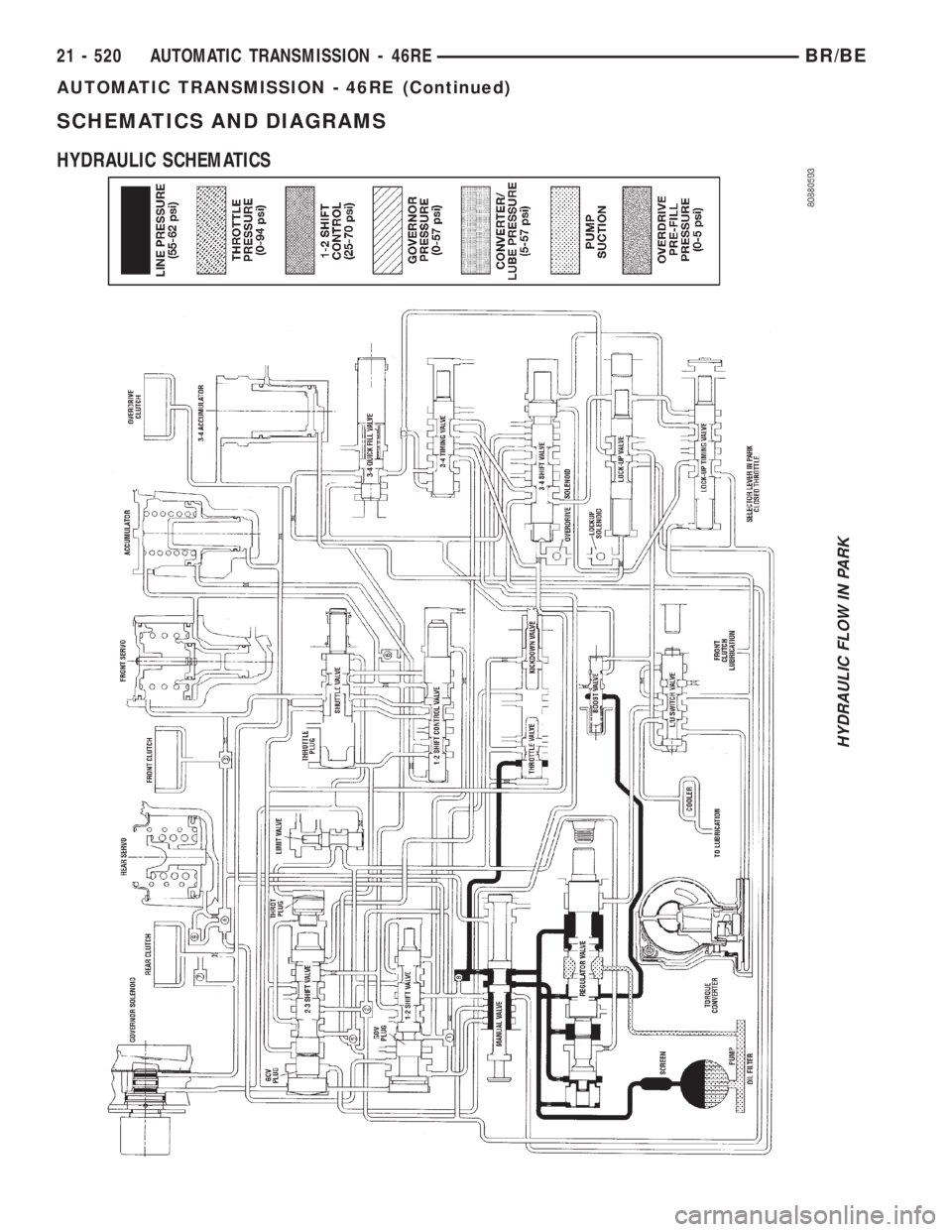
SCHEMATICS AND DIAGRAMS
HYDRAULIC SCHEMATICS
HYDRAULIC FLOW IN PARK
21 - 520 AUTOMATIC TRANSMISSION - 46REBR/BE
AUTOMATIC TRANSMISSION - 46RE (Continued)
Page 2248 of 2889
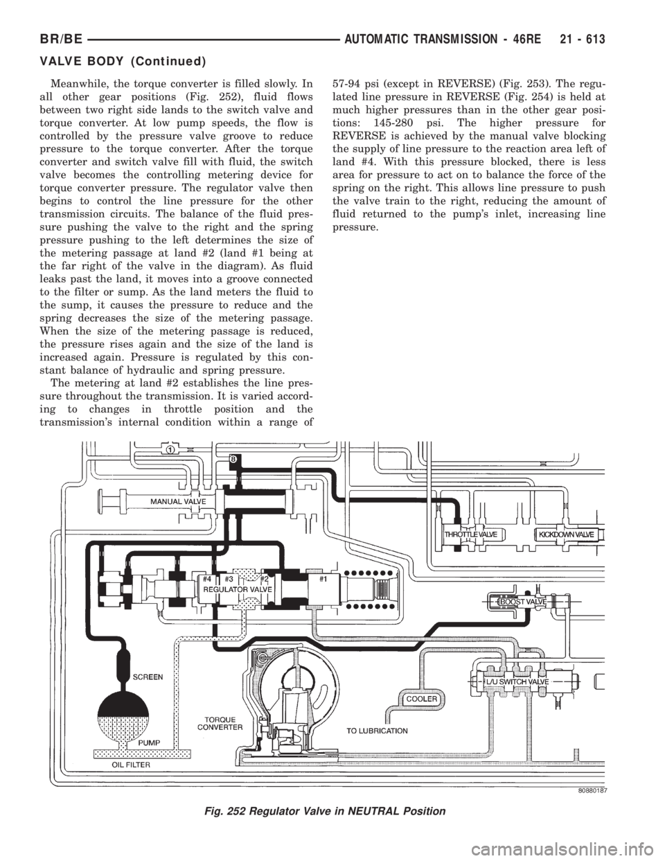
Meanwhile, the torque converter is filled slowly. In
all other gear positions (Fig. 252), fluid flows
between two right side lands to the switch valve and
torque converter. At low pump speeds, the flow is
controlled by the pressure valve groove to reduce
pressure to the torque converter. After the torque
converter and switch valve fill with fluid, the switch
valve becomes the controlling metering device for
torque converter pressure. The regulator valve then
begins to control the line pressure for the other
transmission circuits. The balance of the fluid pres-
sure pushing the valve to the right and the spring
pressure pushing to the left determines the size of
the metering passage at land #2 (land #1 being at
the far right of the valve in the diagram). As fluid
leaks past the land, it moves into a groove connected
to the filter or sump. As the land meters the fluid to
the sump, it causes the pressure to reduce and the
spring decreases the size of the metering passage.
When the size of the metering passage is reduced,
the pressure rises again and the size of the land is
increased again. Pressure is regulated by this con-
stant balance of hydraulic and spring pressure.
The metering at land #2 establishes the line pres-
sure throughout the transmission. It is varied accord-
ing to changes in throttle position and the
transmission's internal condition within a range of57-94 psi (except in REVERSE) (Fig. 253). The regu-
lated line pressure in REVERSE (Fig. 254) is held at
much higher pressures than in the other gear posi-
tions: 145-280 psi. The higher pressure for
REVERSE is achieved by the manual valve blocking
the supply of line pressure to the reaction area left of
land #4. With this pressure blocked, there is less
area for pressure to act on to balance the force of the
spring on the right. This allows line pressure to push
the valve train to the right, reducing the amount of
fluid returned to the pump's inlet, increasing line
pressure.
Fig. 252 Regulator Valve in NEUTRAL Position
BR/BEAUTOMATIC TRANSMISSION - 46RE 21 - 613
VALVE BODY (Continued)