2001 DODGE RAM diagram
[x] Cancel search: diagramPage 1143 of 2889
which replace all in-line fusible links. The PDC also
houses up to thirteen blade-type fuses (two standard-
type and eleven mini-type), up to seventeen Interna-
tional Standards Organization (ISO) relays (five
standard-type and twelve micro-type), two joint con-
nectors (one eighteen-way and one twenty-eight-way),
a forty-three-way engine wire harness in-line connec-
tor and a fuse puller.
The PDC housing is secured in the engine compart-
ment on the outboard side with two screws to the left
front inner fender shield, and with a screw on the
inboard side to the left front inner wheel house. The
PDC housing has a molded plastic cover that
includes two integral latches, one on each side. The
PDC cover is easily opened and removed for service
access and has a convenient adhesive-backed fuse
and relay layout map affixed to the inside surface of
the cover to ensure proper component identification.
The PDC unit cannot be repaired and is only ser-
viced as a unit with the headlamp and dash wire
harness. If the internal circuits or the PDC housing
are faulty or damaged, the headlamp and dash wire
harness unit must be replaced.
OPERATION
All of the current from the battery and the gener-
ator output enters the PDC through two cables with
eyelets that are secured with nuts to the two B(+)
terminal studs located just inside the inboard end of
the PDC housing. The PDC cover is unlatched and
removed to access the battery and generator output
connection B(+) terminal studs, the fuses, the relays,
the joint connectors and the engine wire harness in-
line connector. Internal connection of all of the PDC
circuits is accomplished by an intricate combination
of hard wiring and bus bars. Refer toPower Distri-
butionin the index of this service manual for the
location of complete PDC circuit diagrams.
REMOVAL
The Power Distribution Center (PDC) is serviced
as a unit with the headlamp and dash wire harness.
If any internal circuit of the PDC or the PDC hous-
ing is faulty or damaged, the entire PDC and head-
lamp and dash wire harness unit must be replaced.
(1) Disconnect and isolate the battery negative
cable.
(2) Disconnect each of the headlamp and dash wire
harness connectors. Refer toConnector Locations
in the index of this service manual for the location of
more information on the headlamp and dash wire
harness connector locations.
(3) Remove all of the fasteners that secure each of
the headlamp and dash wire harness ground eyelets
to the vehicle body and chassis components. Refer to
Connector Locationsin the index of this servicemanual for the location of more information on the
ground eyelet locations.
(4) Disengage each of the retainers that secure the
headlamp and dash wire harness to the vehicle body
and chassis components. Refer toConnector Loca-
tionsin the index of this service manual for the loca-
tion of more information on the headlamp and dash
wire harness retainer locations.
(5) Unlatch and remove the cover from the PDC.
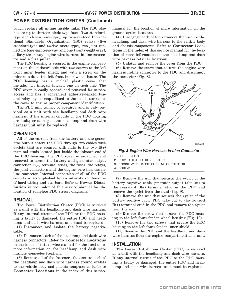
(6) Remove the screw that secures the engine wire
harness in-line connector to the PDC and disconnect
the connector (Fig. 8).
(7) Remove the nut that secures the eyelet of the
battery negative cable generator output take out to
the rearward B(+) terminal stud in the PDC and
remove the eyelet from the stud (Fig. 9).
(8) Remove the nut that secures the eyelet of the
battery positive cable PDC take out to the forward
B(+) terminal stud in the PDC and remove the eyelet
from the stud.
(9) Remove the screw that secures the PDC hous-
ing to the left front fender wheel housing (Fig. 10).
(10) Remove the two screws that secure the PDC
housing to the left front fender inner shield.
(11) Remove the PDC and the headlamp and dash
wire harness from the engine compartment as a unit.
INSTALLATION
The Power Distribution Center (PDC) is serviced
as a unit with the headlamp and dash wire harness.
If any internal circuit of the PDC or the PDC hous-
ing is faulty or damaged, the entire PDC and head-
lamp and dash wire harness unit must be replaced.
Fig. 8 Engine Wire Harness In-Line Connector
1 - LEFT FENDER
2 - POWER DISTRIBUTION CENTER
3 - ENGINE WIRE HARNESS IN-LINE CONNECTOR
4 - SCREW
8W - 97 - 8 8W-97 POWER DISTRIBUTIONBR/BE
POWER DISTRIBUTION CENTER (Continued)
Page 1145 of 2889
the instrument panel, below the radio. The power
outlet base is secured by a snap fit within the instru-
ment panel. A plastic protective cap snaps into the
power outlet base when the power outlet is not being
used, and hangs from the power outlet base mount
by an integral bail strap while the power outlet is in
use.
The power outlet receptacle unit and the accessory
power outlet protective cap are available for service.
The power outlet receptacle cannot be repaired and,
if faulty or damaged, it must be replaced.
OPERATION
The power outlet base or receptacle shell is con-
nected to ground, and an insulated contact in the
bottom of the shell is connected to battery current.
The power outlet receives battery voltage from a fuse
in the Power Distribution Center (PDC) at all times.
While the power outlet is very similar to a cigar
lighter base unit, it does not include the two small
spring-clip retainers inside the bottom of the recepta-
cle shell that are used to secure the cigar lighter
heating element to the insulated contact.
DIAGNOSIS & TESTING - POWER OUTLET
For complete circuit diagrams, refer toPower
Outletin Wiring Diagrams.
WARNING: ON VEHICLES EQUIPPED WITH AIR-
BAGS, REFER TO GROUP 8M - PASSIVE
RESTRAINT SYSTEMS BEFORE ATTEMPTING ANY
STEERING WHEEL, STEERING COLUMN, OR
INSTRUMENT PANEL COMPONENT DIAGNOSIS OR
SERVICE. FAILURE TO TAKE THE PROPER PRE-
CAUTIONS COULD RESULT IN ACCIDENTAL AIR-
BAG DEPLOYMENT AND POSSIBLE PERSONAL
INJURY.
(1) Check the fused B(+) fuse in the Power Distri-
bution Center (PDC). If OK, go to Step 2. If not OK,
repair the shorted circuit or component as required
and replace the faulty fuse.
(2) Check for battery voltage at the fused B(+) fuse
in the PDC. If OK, go to Step 3. If not OK, repair the
open fused B(+) circuit to the battery as required.
(3) Remove the plastic protective cap from the
power outlet receptacle. Check for continuity between
the inside circumference of the power outlet recepta-
cle and a good ground. There should be continuity. If
OK, go to Step 4. If not OK, go to Step 5.
(4) Check for battery voltage at the insulated con-
tact located at the back of the power outlet recepta-
cle. If not OK, go to Step 5.
(5) Disconnect and isolate the battery negative
cable. Remove the power outlet receptacle from the
instrument panel. Disconnect the wire harness con-
nector from the power outlet receptacle. Check forcontinuity between the ground circuit cavity of the
power outlet wire harness connector and a good
ground. There should be continuity. If OK, go to Step
6. If not OK, repair the open ground circuit to ground
as required.
(6) Connect the battery negative cable. Check for
battery voltage at the fused B(+) circuit cavity of the
power outlet wire harness connector. If OK, replace
the faulty power outlet receptacle. If not OK, repair
the open fused B(+) circuit to the PDC fuse as
required.
REMOVAL
(1) Disconnect and isolate the battery negative
cable.
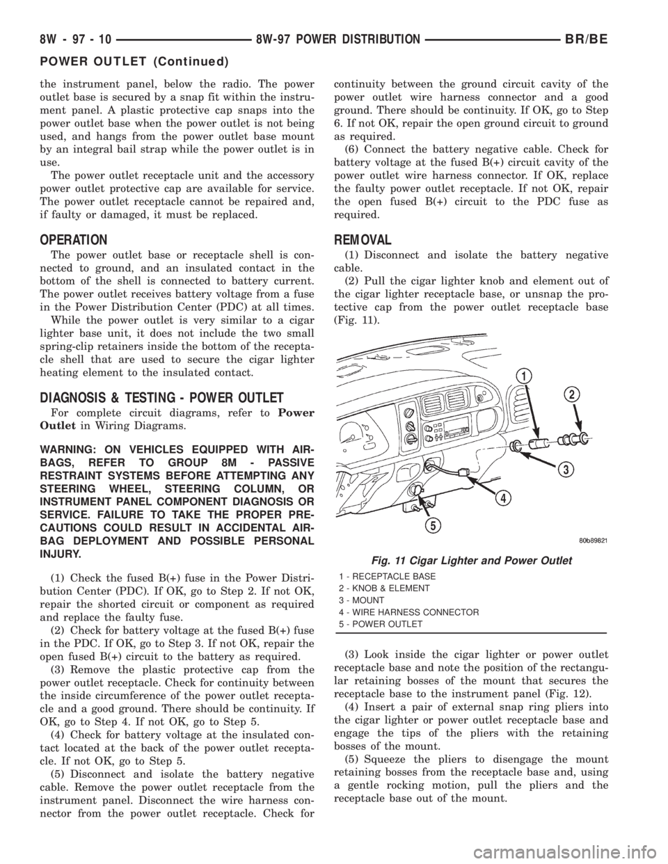
(2) Pull the cigar lighter knob and element out of
the cigar lighter receptacle base, or unsnap the pro-
tective cap from the power outlet receptacle base
(Fig. 11).
(3) Look inside the cigar lighter or power outlet
receptacle base and note the position of the rectangu-
lar retaining bosses of the mount that secures the
receptacle base to the instrument panel (Fig. 12).
(4) Insert a pair of external snap ring pliers into
the cigar lighter or power outlet receptacle base and
engage the tips of the pliers with the retaining
bosses of the mount.
(5) Squeeze the pliers to disengage the mount
retaining bosses from the receptacle base and, using
a gentle rocking motion, pull the pliers and the
receptacle base out of the mount.
Fig. 11 Cigar Lighter and Power Outlet
1 - RECEPTACLE BASE
2 - KNOB & ELEMENT
3 - MOUNT
4 - WIRE HARNESS CONNECTOR
5 - POWER OUTLET
8W - 97 - 10 8W-97 POWER DISTRIBUTIONBR/BE
POWER OUTLET (Continued)
Page 1533 of 2889
(3) Install MAP sensor mounting bolts (screws).
Tighten screws to 3 N´m (25 in. lbs.) torque.
(4) Install air cleaner.
INSTALLATION - 8.0L
The MAP sensor is mounted into the right upper
side of the intake manifold (Fig. 38). A rubber gasket
is used to seal the sensor to the intake manifold. The
rubber gasket is part of the sensor and is not ser-
viced separately.
(1) Check the condition of the sensor seal. Clean
the sensor and lubricate the rubber gasket with clean
engine oil.
(2) Clean the sensor opening in the intake mani-
fold.
(3) Install the sensor into the intake manifold.
(4) Install sensor mounting bolts. Tighten bolts to
2 N´m (20 in. lbs.) torque.
(5) Install the electrical connector to sensor.
O2 SENSOR
DESCRIPTION
The Oxygen Sensors (O2S) are attached to, and
protrude into the vehicle exhaust system. Depending
on the emission package, the vehicle may use a total
of either 2 or 4 sensors.
3.9L/5.2L/Light Duty 5.9L Engine:Four sensors
are used: 2 upstream (referred to as 1/1 and 2/1) and
2 downstream (referred to as 1/2 and 2/2). With this
emission package, the right upstream sensor (2/1) is
located in the right exhaust downpipe just before the
mini-catalytic convertor. The left upstream sensor
(1/1) is located in the left exhaust downpipe just
before the mini-catalytic convertor. The right down-
stream sensor (2/2) is located in the right exhaust
downpipe just after the mini-catalytic convertor, and
before the main catalytic convertor. The left down-
stream sensor (1/2) is located in the left exhaust
downpipe just after the mini-catalytic convertor, and
before the main catalytic convertor.
Medium and Heavy Duty 8.0L V-10 Engine:
Four sensors are used (2 upstream, 1 pre-catalyst
and 1 post-catalyst). With this emission package, the
1/1 upstream sensor (left side) is located in the left
exhaust downpipe before both the pre-catalyst sensor
(1/2), and the main catalytic convertor. The 2/1
upstream sensor (right side) is located in the right
exhaust downpipe before both the pre-catalyst sensor
(1/2), and the main catalytic convertor. The pre-cata-
lyst sensor (1/2) is located after the 1/1 and 2/1 sen-
sors, and just before the main catalytic convertor.
The post-catalyst sensor (1/3) is located just after the
main catalytic convertor.Heavy Duty 5.9L Engine:Two sensors are used.
They arebothreferred to as upstream sensors (left
side is referred to as 1/1 and right side is referred to
as 2/1). With this emission package, a sensor is
located in each of the exhaust downpipes before the
main catalytic convertor.
OPERATION
An O2 sensor is a galvanic battery that provides
the PCM with a voltage signal (0-1 volt) inversely
proportional to the amount of oxygen in the exhaust.
In other words, if the oxygen content is low, the volt-
age output is high; if the oxygen content is high the
output voltage is low. The PCM uses this information
to adjust injector pulse-width to achieve the
14.7±to±1 air/fuel ratio necessary for proper engine
operation and to control emissions.
The O2 sensor must have a source of oxygen from
outside of the exhaust stream for comparison. Cur-
rent O2 sensors receive their fresh oxygen (outside
air) supply through the wire harness. This is why it
is important to never solder an O2 sensor connector,
or pack the connector with grease.
Four wires (circuits) are used on each O2 sensor: a
12±volt feed circuit for the sensor heating element; a
ground circuit for the heater element; a low-noise
sensor return circuit to the PCM, and an input cir-
cuit from the sensor back to the PCM to detect sen-
sor operation.
Oxygen Sensor Heaters/Heater Relays:
Depending on the emissions package, the heating ele-
ments within the sensors will be supplied voltage
from either the ASD relay, or 2 separate oxygen sen-
sor relays. Refer to 8, Wiring Diagrams to determine
which relays are used.
The O2 sensor uses a Positive Thermal Co-efficient
(PTC) heater element. As temperature increases,
resistance increases. At ambient temperatures
around 70ÉF, the resistance of the heating element is
approximately 4.5 ohms. As the sensor's temperature
increases, resistance in the heater element increases.
This allows the heater to maintain the optimum
operating temperature of approximately 930É-1100ÉF
(500É-600É C). Although the sensors operate the
same, there are physical differences, due to the envi-
ronment that they operate in, that keep them from
being interchangeable.
Maintaining correct sensor temperature at all times
allows the system to enter into closed loop operation
sooner. Also, it allows the system to remain in closed
loop operation during periods of extended idle.
In Closed Loop operation, the PCM monitors cer-
tain O2 sensor input(s) along with other inputs, and
adjusts the injector pulse width accordingly. During
Open Loop operation, the PCM ignores the O2 sensor
input. The PCM adjusts injector pulse width based
14 - 46 FUEL INJECTION - GASOLINEBR/BE
MANIFOLD ABSOLUTE PRESSURE SENSOR (Continued)
Page 1603 of 2889
DIAGNOSIS AND TESTING - IGNITION SWITCH
AND KEY LOCK CYLINDER
ELECTRICAL DIAGNOSIS
For ignition switch electrical schematics, refer to
Ignition Switch in the appropriate section of Electri-
cal Wiring Diagrams.
MECHANICAL DIAGNOSIS (KEY DIFFICULT TO
ROTATE)
Vehicles equipped with an automatic trans-
mission and a floor mounted shifter:a cable is
used to connect the interlock device in the steering
column assembly, to the transmission floor shift
lever. This interlock device is used to lock the trans-
mission shifter in the PARK position when the key
lock cylinder is rotated to the LOCKED or ACCES-
SORY position. The interlock device within the steer-
ing column is not serviceable. If repair is necessary,
the steering column assembly must be replaced.
(Refer to 19 - STEERING/COLUMN - REMOVAL).
If the ignition key is difficult to rotate to or from
the LOCK or ACCESSORY position, it may not be
the fault of the key cylinder or the steering column
components. The brake transmission shift interlock
cable may be out of adjustment. Refer to Brake
Transmission Shift Interlock Cable Adjustment in
Transmissions for adjustment procedures.
Vehicles equipped with an automatic trans-
mission and a steering column mounted shifter:
an interlock device is located within the steering col-
umn. This interlock device is used to lock the trans-
mission shifter in the PARK position when the key
lock cylinder is in the LOCKED or ACCESSORY
position. If it is difficult to rotate the key to or from
the LOCK or ACCESSORY position, the interlock
device within the steering column may be defective.
This device is not serviceable. If repair is necessary,
the steering column assembly must be replaced.
(Refer to 19 - STEERING/COLUMN - REMOVAL).
Vehicles equipped with a manual transmis-
sion and a floor mounted shifter:on certain mod-
els, a lever is located on the steering column behind
the ignition key lock cylinder. The lever must be
manually operated to allow rotation of the ignition
key lock cylinder to the LOCK or ACCESSORY posi-
tion. If it is difficult to rotate the key to the LOCK or
ACCESSORY position, the lever mechanism may be
defective. This mechanism is not serviceable. If
repair is necessary, the steering column assembly
must be replaced. (Refer to 19 - STEERING/COL-
UMN - REMOVAL).
On other models, the ignition key cylinder must be
depressed to allow it to be rotated into the LOCK or
ACCESSORY position. If it is difficult to rotate the
key to the LOCK or ACCESSORY position, the lockmechanism within the steering column may be defec-
tive. This mechanism is not serviceable. If repair is
necessary, the steering column assembly must be
replaced. (Refer to 19 - STEERING/COLUMN -
REMOVAL).
LOCK CYLINDER HOUSING
REMOVAL
The ignition key must be in the key cylinder for
cylinder removal.
(1) Disconnect negative cable from battery.
(2) If equipped with tilt column, remove tilt lever
by turning it counterclockwise.
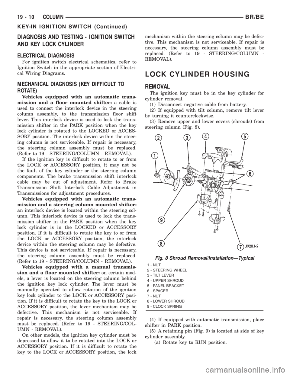
(3) Remove upper and lower covers (shrouds) from
steering column (Fig. 8).
(4) If equipped with automatic transmission, place
shifter in PARK position.
(5) A retaining pin (Fig. 9) is located at side of key
cylinder assembly.
(a) Rotate key to RUN position.
Fig. 8 Shroud Removal/InstallationÐTypical
1 - NUT
2 - STEERING WHEEL
3 - TILT LEVER
4 - UPPER SHROUD
5 - PANEL BRACKET
6 - SPACER
7 - NUT
8 - LOWER SHROUD
9 - CLOCK SPRING
19 - 10 COLUMNBR/BE
KEY-IN IGNITION SWITCH (Continued)
Page 1769 of 2889
AUTOMATIC TRANSMISSION - 42RE
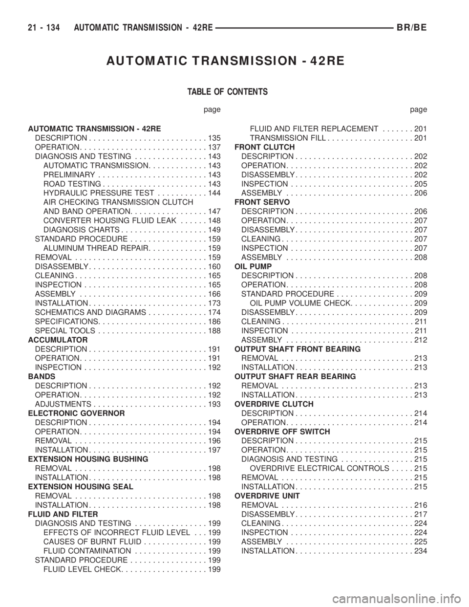
TABLE OF CONTENTS
page page
AUTOMATIC TRANSMISSION - 42RE
DESCRIPTION..........................135
OPERATION............................137
DIAGNOSIS AND TESTING................143
AUTOMATIC TRANSMISSION.............143
PRELIMINARY........................143
ROAD TESTING.......................143
HYDRAULIC PRESSURE TEST...........144
AIR CHECKING TRANSMISSION CLUTCH
AND BAND OPERATION.................147
CONVERTER HOUSING FLUID LEAK......148
DIAGNOSIS CHARTS...................149
STANDARD PROCEDURE.................159
ALUMINUM THREAD REPAIR.............159
REMOVAL.............................159
DISASSEMBLY..........................160
CLEANING.............................165
INSPECTION...........................165
ASSEMBLY............................166
INSTALLATION..........................173
SCHEMATICS AND DIAGRAMS.............174
SPECIFICATIONS........................186
SPECIAL TOOLS........................188
ACCUMULATOR
DESCRIPTION..........................191
OPERATION............................191
INSPECTION...........................192
BANDS
DESCRIPTION..........................192
OPERATION............................192
ADJUSTMENTS.........................193
ELECTRONIC GOVERNOR
DESCRIPTION..........................194
OPERATION............................194
REMOVAL.............................196
INSTALLATION..........................197
EXTENSION HOUSING BUSHING
REMOVAL.............................198
INSTALLATION..........................198
EXTENSION HOUSING SEAL
REMOVAL.............................198
INSTALLATION..........................198
FLUID AND FILTER
DIAGNOSIS AND TESTING................199
EFFECTS OF INCORRECT FLUID LEVEL . . . 199
CAUSES OF BURNT FLUID..............199
FLUID CONTAMINATION................199
STANDARD PROCEDURE.................199
FLUID LEVEL CHECK...................199FLUID AND FILTER REPLACEMENT.......201
TRANSMISSION FILL...................201
FRONT CLUTCH
DESCRIPTION..........................202
OPERATION............................202
DISASSEMBLY..........................202
INSPECTION...........................205
ASSEMBLY............................206
FRONT SERVO
DESCRIPTION..........................206
OPERATION............................207
DISASSEMBLY..........................207
CLEANING.............................207
INSPECTION...........................207
ASSEMBLY............................208
OIL PUMP
DESCRIPTION..........................208
OPERATION............................208
STANDARD PROCEDURE.................209
OIL PUMP VOLUME CHECK..............209
DISASSEMBLY..........................209
CLEANING.............................211
INSPECTION...........................211
ASSEMBLY............................212
OUTPUT SHAFT FRONT BEARING
REMOVAL.............................213
INSTALLATION..........................213
OUTPUT SHAFT REAR BEARING
REMOVAL.............................213
INSTALLATION..........................213
OVERDRIVE CLUTCH
DESCRIPTION..........................214
OPERATION............................214
OVERDRIVE OFF SWITCH
DESCRIPTION..........................215
OPERATION............................215
DIAGNOSIS AND TESTING................215
OVERDRIVE ELECTRICAL CONTROLS.....215
REMOVAL.............................215
INSTALLATION..........................215
OVERDRIVE UNIT
REMOVAL.............................216
DISASSEMBLY..........................217
CLEANING.............................224
INSPECTION...........................224
ASSEMBLY............................225
INSTALLATION..........................234
21 - 134 AUTOMATIC TRANSMISSION - 42REBR/BE
Page 1784 of 2889
plug threads and tighten plug to 17 N´m (150 in. lbs.)
torque.
(7) Adjust front band.
(8) Lubricate pump seal and converter hub with
transmission fluid or petroleum jelly and install con-
verter.
(9) Install transmission and converter housing
dust shield.
(10) Lower vehicle.
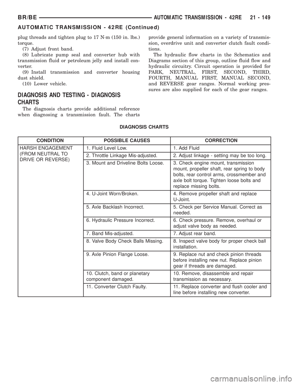
DIAGNOSIS AND TESTING - DIAGNOSIS
CHARTS
The diagnosis charts provide additional reference
when diagnosing a transmission fault. The chartsprovide general information on a variety of transmis-
sion, overdrive unit and converter clutch fault condi-
tions.
The hydraulic flow charts in the Schematics and
Diagrams section of this group, outline fluid flow and
hydraulic circuitry. Circuit operation is provided for
PARK, NEUTRAL, FIRST, SECOND, THIRD,
FOURTH, MANUAL FIRST, MANUAL SECOND,
and REVERSE gear ranges. Normal working pres-
sures are also supplied for each of the gear ranges.
DIAGNOSIS CHARTS
CONDITION POSSIBLE CAUSES CORRECTION
HARSH ENGAGEMENT
(FROM NEUTRAL TO
DRIVE OR REVERSE)1. Fluid Level Low. 1. Add Fluid
2. Throttle Linkage Mis-adjusted. 2. Adjust linkage - setting may be too long.
3. Mount and Driveline Bolts Loose. 3. Check engine mount, transmission
mount, propeller shaft, rear spring to body
bolts, rear control arms, crossmember and
axle bolt torque. Tighten loose bolts and
replace missing bolts.
4. U-Joint Worn/Broken. 4. Remove propeller shaft and replace
U-Joint.
5. Axle Backlash Incorrect. 5. Check per Service Manual. Correct as
needed.
6. Hydraulic Pressure Incorrect. 6. Check pressure. Remove, overhaul or
adjust valve body as needed.
7. Band Mis-adjusted. 7. Adjust rear band.
8. Valve Body Check Balls Missing. 8. Inspect valve body for proper check ball
installation.
9. Axle Pinion Flange Loose. 9. Replace nut and check pinion threads
before installing new nut. Replace pinion
gear if threads are damaged.
10. Clutch, band or planetary
component damaged.10. Remove, disassemble and repair
transmission as necessary.
11. Converter Clutch Faulty. 11. Replace converter and flush cooler and
line before installing new converter.
BR/BEAUTOMATIC TRANSMISSION - 42RE 21 - 149
AUTOMATIC TRANSMISSION - 42RE (Continued)
Page 1809 of 2889
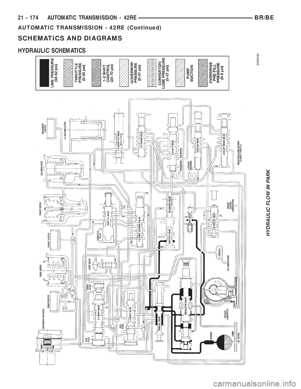
SCHEMATICS AND DIAGRAMS
HYDRAULIC SCHEMATICS
HYDRAULIC FLOW IN PARK
21 - 174 AUTOMATIC TRANSMISSION - 42REBR/BE
AUTOMATIC TRANSMISSION - 42RE (Continued)
Page 1903 of 2889
REGULATOR VALVE
The pressure regulator valve is needed to control
the hydraulic pressure within the system and reduce
the amount of heat produced in the fluid. The pres-
sure regulator valve is located in the valve body near
the manual valve. The pressure regulator valve train
controls the maximum pressure in the lines by
metering the dumping of fluid back into the sump.
Regulated pressure is referred to as ªline pressure.º
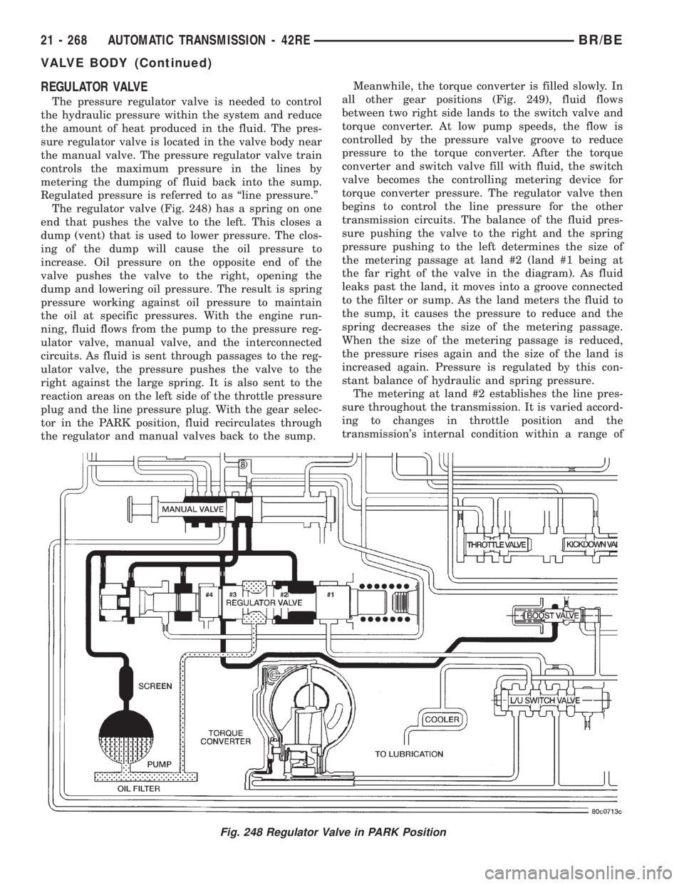
The regulator valve (Fig. 248) has a spring on one
end that pushes the valve to the left. This closes a
dump (vent) that is used to lower pressure. The clos-
ing of the dump will cause the oil pressure to
increase. Oil pressure on the opposite end of the
valve pushes the valve to the right, opening the
dump and lowering oil pressure. The result is spring
pressure working against oil pressure to maintain
the oil at specific pressures. With the engine run-
ning, fluid flows from the pump to the pressure reg-
ulator valve, manual valve, and the interconnected
circuits. As fluid is sent through passages to the reg-
ulator valve, the pressure pushes the valve to the
right against the large spring. It is also sent to the
reaction areas on the left side of the throttle pressure
plug and the line pressure plug. With the gear selec-
tor in the PARK position, fluid recirculates through
the regulator and manual valves back to the sump.Meanwhile, the torque converter is filled slowly. In
all other gear positions (Fig. 249), fluid flows
between two right side lands to the switch valve and
torque converter. At low pump speeds, the flow is
controlled by the pressure valve groove to reduce
pressure to the torque converter. After the torque
converter and switch valve fill with fluid, the switch
valve becomes the controlling metering device for
torque converter pressure. The regulator valve then
begins to control the line pressure for the other
transmission circuits. The balance of the fluid pres-
sure pushing the valve to the right and the spring
pressure pushing to the left determines the size of
the metering passage at land #2 (land #1 being at
the far right of the valve in the diagram). As fluid
leaks past the land, it moves into a groove connected
to the filter or sump. As the land meters the fluid to
the sump, it causes the pressure to reduce and the
spring decreases the size of the metering passage.
When the size of the metering passage is reduced,
the pressure rises again and the size of the land is
increased again. Pressure is regulated by this con-
stant balance of hydraulic and spring pressure.
The metering at land #2 establishes the line pres-
sure throughout the transmission. It is varied accord-
ing to changes in throttle position and the
transmission's internal condition within a range of
Fig. 248 Regulator Valve in PARK Position
21 - 268 AUTOMATIC TRANSMISSION - 42REBR/BE
VALVE BODY (Continued)