2001 DODGE RAM instrument cluster
[x] Cancel search: instrument clusterPage 1015 of 2889
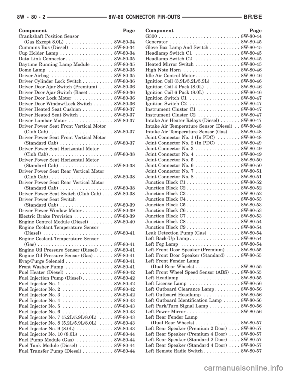
Component Page
Crankshaft Position Sensor
(Gas Except 8.0L)................. 8W-80-34
Cummins Bus (Diesel)............... 8W-80-34
Cup Holder Lamp................... 8W-80-34
Data Link Connector................. 8W-80-35
Daytime Running Lamp Module........ 8W-80-35
Dome Lamp....................... 8W-80-35
Driver Airbag...................... 8W-80-35
Driver Cylinder Lock Switch........... 8W-80-36
Driver Door Ajar Switch (Premium)..... 8W-80-36
Driver Door Ajar Switch (Base)......... 8W-80-36
Driver Door Lock Motor.............. 8W-80-36
Driver Door Window/Lock Switch....... 8W-80-36
Driver Heated Seat Cushion........... 8W-80-37
Driver Heated Seat Switch............ 8W-80-37
Driver Lumbar Motor................ 8W-80-37
Driver Power Seat Front Vertical Motor
(Club Cab)....................... 8W-80-37
Driver Power Seat Front Vertical Motor
(Standard Cab)................... 8W-80-37
Driver Power Seat Horizontal Motor
(Club Cab)....................... 8W-80-38
Driver Power Seat Horizontal Motor
(Standard Cab)................... 8W-80-38
Driver Power Seat Rear Vertical Motor
(Club Cab)....................... 8W-80-38
Driver Power Seat Rear Vertical Motor
(Standard Cab)................... 8W-80-38
Driver Power Seat Switch (Club Cab).... 8W-80-38
Driver Power Seat Switch
(Standard Cab)................... 8W-80-39
Driver Power Window Motor........... 8W-80-39
Electric Brake Provision.............. 8W-80-39
Engine Control Module (Diesel)........ 8W-80-40
Engine Coolant Temperature Sensor
(Diesel)......................... 8W-80-41
Engine Coolant Temperature Sensor
(Gas)........................... 8W-80-41
Engine Oil Pressure Sensor (Diesel)..... 8W-80-41
Engine Oil Pressure Sensor (Gas)....... 8W-80-41
Evap/Purge Solenoid................. 8W-80-41
Front Washer Pump................. 8W-80-41
Fuel Heater (Diesel)................. 8W-80-42
Fuel Injection Pump (Diesel)........... 8W-80-42
Fuel Injector No. 1.................. 8W-80-42
Fuel Injector No. 2.................. 8W-80-42
Fuel Injector No. 3.................. 8W-80-42
Fuel Injector No. 4.................. 8W-80-43
Fuel Injector No. 5.................. 8W-80-43
Fuel Injector No. 6.................. 8W-80-43
Fuel Injector No. 7 (5.2L/5.9L/8.0L)..... 8W-80-43
Fuel Injector No. 8 (5.2L/5.9L/8.0L)..... 8W-80-43
Fuel Injector No. 9 (8.0L)............. 8W-80-43
Fuel Injector No. 10 (8.0L)............ 8W-80-44
Fuel Pump Module (Gas)............. 8W-80-44
Fuel Tank Module (Diesel)............ 8W-80-44
Fuel Transfer Pump (Diesel)........... 8W-80-44Component Page
G300............................. 8W-80-44
Generator......................... 8W-80-45
Glove Box Lamp And Switch........... 8W-80-45
Headlamp Switch C1................ 8W-80-45
Headlamp Switch C2................ 8W-80-45
Heated Mirror Switch................ 8W-80-45
High Note Horn.................... 8W-80-46
Idle Air Control Motor................ 8W-80-46
Ignition Coil (3.9L/5.2L/5.9L).......... 8W-80-46
Ignition Coil 4 Pack (8.0L)............ 8W-80-46
Ignition Coil 6 Pack (8.0L)............ 8W-80-46
Ignition Switch C1.................. 8W-80-47
Ignition Switch C2.................. 8W-80-47
Instrument Cluster C1............... 8W-80-47
Instrument Cluster C2............... 8W-80-47
Intake Air Heater Relays (Diesel)....... 8W-80-47
Intake Air Temperature Sensor (Diesel) . . 8W-80-48
Intake Air Temperature Sensor (Gas).... 8W-80-48
Joint Connector No. 1 (In PDC)........ 8W-80-48
Joint Connector No. 2 (In PDC)........ 8W-80-49
Joint Connector No. 3................ 8W-80-49
Joint Connector No. 4................ 8W-80-49
Joint Connector No. 5................ 8W-80-50
Joint Connector No. 6................ 8W-80-50
Joint Connector No. 7................ 8W-80-51
Joint Connector No. 8................ 8W-80-51
Junction Block C1................... 8W-80-52
Junction Block C2................... 8W-80-52
Junction Block C3................... 8W-80-52
Junction Block C4................... 8W-80-53
Junction Block C5................... 8W-80-53
Junction Block C6................... 8W-80-53
Junction Block C7................... 8W-80-53
Junction Block C8................... 8W-80-54
Junction Block C9................... 8W-80-54
Leak Detection Pump (Gas)........... 8W-80-54
Left Back-Up Lamp.................. 8W-80-54
Left Fog Lamp..................... 8W-80-54
Left Front Door Speaker (Premium)..... 8W-80-55
Left Front Door Speaker (Standard)..... 8W-80-55
Left Front Fender Lamp
(Dual Rear Wheels)................ 8W-80-55
Left Front Wheel Speed Sensor (ABS) . . . 8W-80-55
Left Headlamp..................... 8W-80-55
Left License Lamp.................. 8W-80-56
Left Outboard Clearance Lamp......... 8W-80-56
Left Outboard Headlamp............. 8W-80-56
Left Outboard Identification Lamp...... 8W-80-56
Left Park/Turn Signal Lamp........... 8W-80-56
Left Power Mirror................... 8W-80-56
Left Rear Fender Lamp
(Dual Rear Wheels)................ 8W-80-57
Left Rear Speaker (Premium 2 Door).... 8W-80-57
Left Rear Speaker (Premium 4 Door).... 8W-80-57
Left Rear Speaker (Standard 2 Door).... 8W-80-57
Left Rear Speaker (Standard 4 Door).... 8W-80-57
Left Remote Radio Switch............. 8W-80-57
8W - 80 - 2 8W-80 CONNECTOR PIN-OUTSBR/BE
Page 1060 of 2889
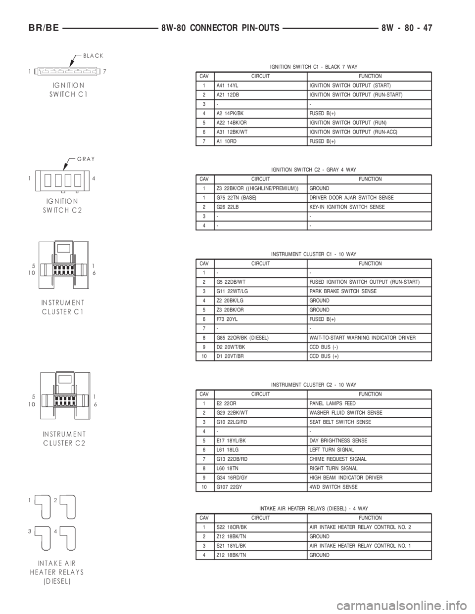
IGNITION SWITCH C1 - BLACK 7 WAY
CAV CIRCUIT FUNCTION
1 A41 14YL IGNITION SWITCH OUTPUT (START)
2 A21 12DB IGNITION SWITCH OUTPUT (RUN-START)
3- -
4 A2 14PK/BK FUSED B(+)
5 A22 14BK/OR IGNITION SWITCH OUTPUT (RUN)
6 A31 12BK/WT IGNITION SWITCH OUTPUT (RUN-ACC)
7 A1 10RD FUSED B(+)
IGNITION SWITCH C2 - GRAY 4 WAY
CAV CIRCUIT FUNCTION
1 Z3 22BK/OR ((HIGHLINE/PREMIUM)) GROUND
1 G75 22TN (BASE) DRIVER DOOR AJAR SWITCH SENSE
2 G26 22LB KEY-IN IGNITION SWITCH SENSE
3- -
4- -
INSTRUMENT CLUSTER C1 - 10 WAY
CAV CIRCUIT FUNCTION
1- -
2 G5 22DB/WT FUSED IGNITION SWITCH OUTPUT (RUN-START)
3 G11 22WT/LG PARK BRAKE SWITCH SENSE
4 Z2 20BK/LG GROUND
5 Z3 20BK/OR GROUND
6 F73 20YL FUSED B(+)
7- -
8 G85 22OR/BK (DIESEL) WAIT-TO-START WARNING INDICATOR DRIVER
9 D2 20WT/BK CCD BUS (-)
10 D1 20VT/BR CCD BUS (+)
INSTRUMENT CLUSTER C2 - 10 WAY
CAV CIRCUIT FUNCTION
1 E2 22OR PANEL LAMPS FEED
2 G29 22BK/WT WASHER FLUID SWITCH SENSE
3 G10 22LG/RD SEAT BELT SWITCH SENSE
4- -
5 E17 18YL/BK DAY BRIGHTNESS SENSE
6 L61 18LG LEFT TURN SIGNAL
7 G13 22DB/RD CHIME REQUEST SIGNAL
8 L60 18TN RIGHT TURN SIGNAL
9 G34 16RD/GY HIGH BEAM INDICATOR DRIVER
10 G107 22GY 4WD SWITCH SENSE
INTAKE AIR HEATER RELAYS (DIESEL)-4WAY
CAV CIRCUIT FUNCTION
1 S22 18OR/BK AIR INTAKE HEATER RELAY CONTROL NO. 2
2 Z12 18BK/TN GROUND
3 S21 18YL/BK AIR INTAKE HEATER RELAY CONTROL NO. 1
4 Z12 18BK/TN GROUND
BR/BE8W-80 CONNECTOR PIN-OUTS 8W - 80 - 47
Page 1095 of 2889
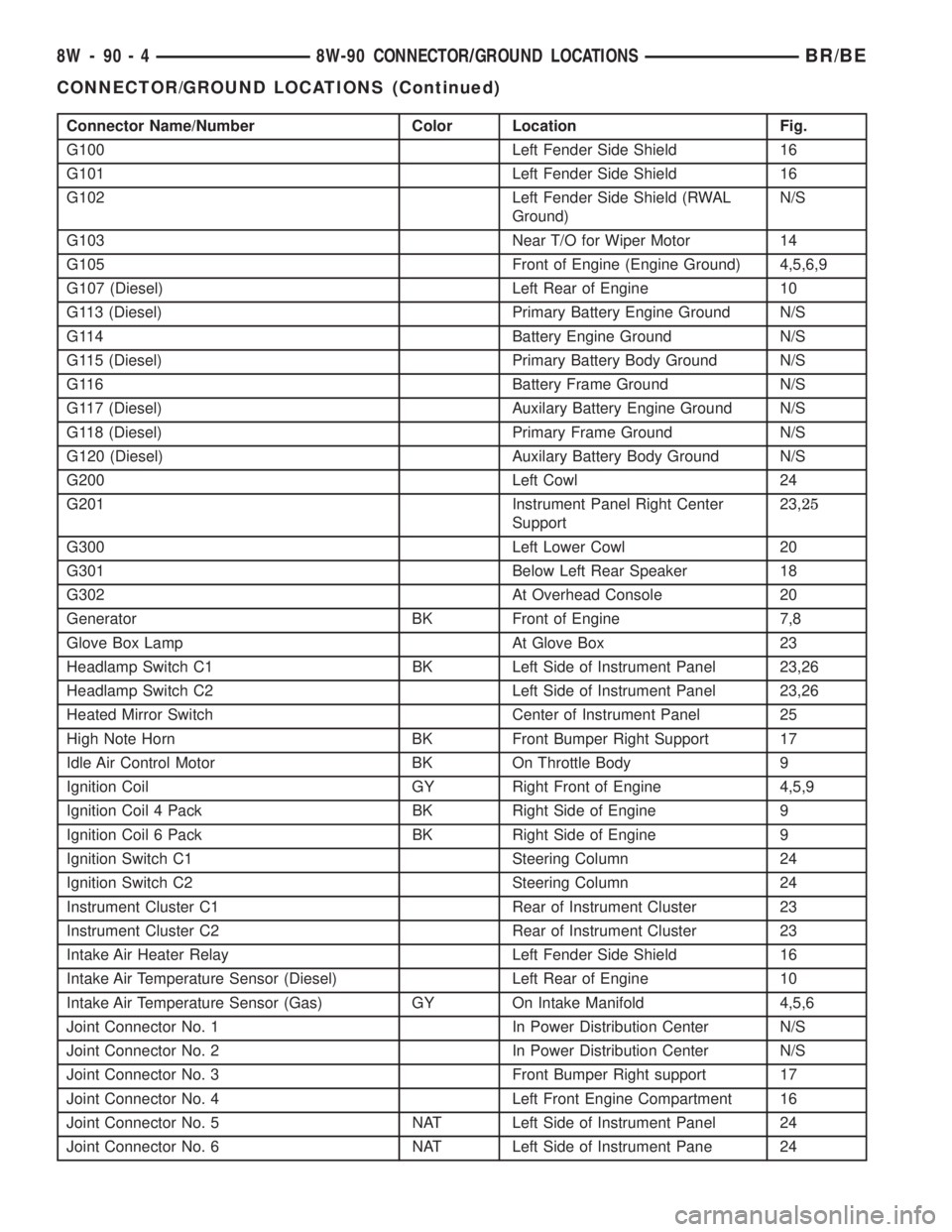
Connector Name/Number Color Location Fig.
G100 Left Fender Side Shield 16
G101 Left Fender Side Shield 16
G102 Left Fender Side Shield (RWAL
Ground)N/S
G103 Near T/O for Wiper Motor 14
G105 Front of Engine (Engine Ground) 4,5,6,9
G107 (Diesel) Left Rear of Engine 10
G113 (Diesel) Primary Battery Engine Ground N/S
G114 Battery Engine Ground N/S
G115 (Diesel) Primary Battery Body Ground N/S
G116 Battery Frame Ground N/S
G117 (Diesel) Auxilary Battery Engine Ground N/S
G118 (Diesel) Primary Frame Ground N/S
G120 (Diesel) Auxilary Battery Body Ground N/S
G200 Left Cowl 24
G201 Instrument Panel Right Center
Support23,25
G300 Left Lower Cowl 20
G301 Below Left Rear Speaker 18
G302 At Overhead Console 20
Generator BK Front of Engine 7,8
Glove Box Lamp At Glove Box 23
Headlamp Switch C1 BK Left Side of Instrument Panel 23,26
Headlamp Switch C2 Left Side of Instrument Panel 23,26
Heated Mirror Switch Center of Instrument Panel 25
High Note Horn BK Front Bumper Right Support 17
Idle Air Control Motor BK On Throttle Body 9
Ignition Coil GY Right Front of Engine 4,5,9
Ignition Coil 4 Pack BK Right Side of Engine 9
Ignition Coil 6 Pack BK Right Side of Engine 9
Ignition Switch C1 Steering Column 24
Ignition Switch C2 Steering Column 24
Instrument Cluster C1 Rear of Instrument Cluster 23
Instrument Cluster C2 Rear of Instrument Cluster 23
Intake Air Heater Relay Left Fender Side Shield 16
Intake Air Temperature Sensor (Diesel) Left Rear of Engine 10
Intake Air Temperature Sensor (Gas) GY On Intake Manifold 4,5,6
Joint Connector No. 1 In Power Distribution Center N/S
Joint Connector No. 2 In Power Distribution Center N/S
Joint Connector No. 3 Front Bumper Right support 17
Joint Connector No. 4 Left Front Engine Compartment 16
Joint Connector No. 5 NAT Left Side of Instrument Panel 24
Joint Connector No. 6 NAT Left Side of Instrument Pane 24
8W - 90 - 4 8W-90 CONNECTOR/GROUND LOCATIONSBR/BE
CONNECTOR/GROUND LOCATIONS (Continued)
Page 1495 of 2889
Both of the electrical circuits between the fuel
gauge sending unit and the PCM are hard-wired (not
multi-plexed). After the voltage signal is sent from
the resistor track, and back to the PCM, the PCM
will interpret the resistance (voltage) data and send
a message across the multi-plex bus circuits to the
instrument panel cluster. Here it is translated into
the appropriate fuel gauge level reading. Refer to
Instrument Panel for additional information.
For OBD II Emission Monitor Requirements:
The PCM will monitor the voltage output sent from
the resistor track on the sending unit to indicate fuel
level. The purpose of this feature is to prevent the
OBD II system from recording/setting false misfire
and fuel system monitor diagnostic trouble codes.
The feature is activated if the fuel level in the tank
is less than approximately 15 percent of its rated
capacity. If equipped with a Leak Detection Pump
(EVAP system monitor), this feature will also be acti-
vated if the fuel level in the tank is more than
approximately 85 percent of its rated capacity.
DIAGNOSIS AND TESTING - FUEL GAUGE
SENDING UNIT
The fuel gauge sending unit contains a variable
resistor (track). As the float moves up or down, elec-
trical resistance will change. Refer to 8, Instrument
Panel and Gauges for Fuel Gauge testing. To test the
gauge sending unit only, it must be removed from
vehicle. The unit is part of the fuel pump module.
Refer to Fuel Pump Module Removal/Installation for
procedures. Measure the resistance across the send-
ing unit terminals. With float in up position, resis-
tance should be 20 ohms66 ohms. With float in
down position, resistance should be 220 ohms66
ohms.
REMOVAL
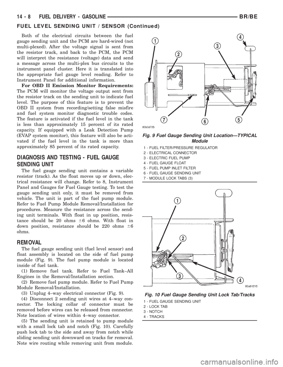
The fuel gauge sending unit (fuel level sensor) and
float assembly is located on the side of fuel pump
module (Fig. 9). The fuel pump module is located
inside of fuel tank.
(1) Remove fuel tank. Refer to Fuel Tank±All
Engines in the Removal/Installation section.
(2) Remove fuel pump module. Refer to Fuel Pump
Module Removal/Installation.
(3) Unplug 4±way electrical connector (Fig. 9).
(4) Disconnect 2 sending unit wires at 4±way con-
nector. The locking collar of connector must be
removed before wires can be released from connector.
Note location of wires within 4±way connector.
(5) The sending unit is retained to pump module
with a small lock tab and notch (Fig. 10). Carefully
push lock tab to the side and away from notch while
sliding sending unit downward on tracks for removal.
Note wire routing while removing unit from module.
Fig. 9 Fuel Gauge Sending Unit LocationÐTYPICAL
Module
1 - FUEL FILTER/PRESSURE REGULATOR
2 - ELECTRICAL CONNECTOR
3 - ELECTRIC FUEL PUMP
4 - FUEL GAUGE FLOAT
5 - FUEL PUMP INLET FILTER
6 - FUEL GAUGE SENDING UNIT
7 - MODULE LOCK TABS (3)
Fig. 10 Fuel Gauge Sending Unit Lock Tab/Tracks
1 - FUEL GAUGE SENDING UNIT
2 - LOCK TAB
3 - NOTCH
4 - TRACKS
14 - 8 FUEL DELIVERY - GASOLINEBR/BE
FUEL LEVEL SENDING UNIT / SENSOR (Continued)
Page 1560 of 2889
(15) Connect 9±way electrical connector to Fuel
Pump Control Module (FPCM) (Fig. 22).
(16) Connect both negative battery cables to both
batteries.
(17) Bleed air from fuel system.(Refer to 14 -
FUEL SYSTEM/FUEL DELIVERY - STANDARD
PROCEDURE).
(18) Check system for fuel or engine oil leaks.
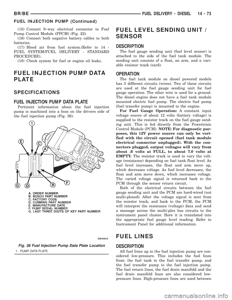
FUEL INJECTION PUMP DATA
PLATE
SPECIFICATIONS
FUEL INJECTION PUMP DATA PLATE
Pertinent information about the fuel injection
pump is machined into a boss on the drivers side of
the fuel injection pump (Fig. 36).
FUEL LEVEL SENDING UNIT /
SENSOR
DESCRIPTION
The fuel gauge sending unit (fuel level sensor) is
attached to the side of the fuel tank module. The
sending unit consists of a float, an arm, and a vari-
able resistor track (card).
OPERATION
The fuel tank module on diesel powered models
has 3 different circuits (wires). Two of these circuits
are used at the fuel gauge sending unit for fuel
gauge operation. The other wire is used for a ground.
The diesel engine does not have a fuel tank module
mounted electric fuel pump. The electric fuel pump
(fuel transfer pump) is mounted to the engine.
For Fuel Gauge Operation:A constant input
voltage source of about 12 volts (battery voltage) is
supplied to the resistor track on the fuel gauge send-
ing unit. This is fed directly from the Powertrain
Control Module (PCM).NOTE: For diagnostic pur-
poses, this 12V power source can only be veri-
fied with the circuit opened (fuel tank module
electrical connector unplugged). With the con-
nectors plugged, output voltages will vary from
about .6 volts at FULL, to about 7.0 volts at
EMPTY.The resistor track is used to vary the volt-
age (resistance) depending on fuel tank float level. As
fuel level increases, the float and arm move up,
which decreases voltage. As fuel level decreases, the
float and arm move down, which increases voltage.
The varied voltage signal is returned back to the
PCM through the sensor return circuit.
Both of the electrical circuits between the fuel
gauge sending unit and the PCM are hard-wired (not
multi-plexed). After the voltage signal is sent from
the resistor track, and back to the PCM, the PCM
will interpret the resistance (voltage) data and send
a message across the multi-plex bus circuits to the
instrument panel cluster. Here it is translated into
the appropriate fuel gauge level reading. Refer to
Instrument Panel for additional information.
FUEL LINES
DESCRIPTION
All fuel lines up to the fuel injection pump are con-
sidered low-pressure. This includes the fuel lines
from: the fuel tank to the fuel transfer pump, and
the fuel transfer pump to the fuel injection pump.
The fuel return lines, the fuel drain manifold and the
fuel drain manifold lines are also considered low-
pressure lines. High-pressure lines are used between
Fig. 36 Fuel Injection Pump Data Plate Location
1 - PUMP DATA PLATE
BR/BEFUEL DELIVERY - DIESEL 14 - 73
FUEL INJECTION PUMP (Continued)
Page 2677 of 2889
INSTRUMENT PANEL SYSTEM
TABLE OF CONTENTS
page page
INSTRUMENT PANEL SYSTEM
DESCRIPTION..........................104
OPERATION............................105
REMOVAL.............................106
INSTALLATION..........................107
ASH RECEIVER
REMOVAL.............................108
INSTALLATION..........................109
CLUSTER BEZEL
REMOVAL.............................109
INSTALLATION..........................110
CUBBY BIN
REMOVAL.............................110
INSTALLATION..........................110
CUP HOLDER
REMOVAL.............................110
INSTALLATION..........................111
GLOVE BOX
REMOVAL.............................112DISASSEMBLY..........................112
ASSEMBLY.............................112
INSTALLATION..........................113
GLOVE BOX LATCH STRIKER
REMOVAL.............................113
INSTALLATION..........................113
GLOVE BOX OPENING UPPER TRIM
REMOVAL.............................114
INSTALLATION..........................114
INSTRUMENT PANEL TOP COVER
REMOVAL.............................114
INSTALLATION..........................115
STEERING COLUMN OPENING COVER
REMOVAL.............................115
INSTALLATION..........................116
STORAGE BIN
REMOVAL.............................116
INSTALLATION..........................116
INSTRUMENT PANEL SYSTEM
DESCRIPTION
The instrument panel is located at the front of the
passenger compartment. This instrument panel is
molded from a blend of various plastics that are
mechanically attached to the vehicle. Colors are
molded into the plastic components to minimize
appearance degradation from scratches or abrasions.
The panel components are internally ribbed and riv-
eted to steel reinforcements for additional structural
integrity and dimensional stability. The instrument
panel surface components are designed to deform
upon impact without breaking. This type of construc-
tion provides improved energy absorption which, in
conjunction with the dual airbags and seat belts,
helps to improve occupant protection.
The top of the instrument panel is secured to the
top of the dash panel near the base of the windshield
using screws. An end bracket integral to each end of
the instrument panel structure is secured to each
cowl side inner panel with a screw. A stamped metal
bracket supports the center of the instrument panel
by securing it to the top of the floor panel transmis-
sion tunnel below the instrument panel with screws.
The instrument cluster, radio, heater-air conditioner
control, passenger airbag, glove box, electrical junc-
tion block, Central Timer Module (CTM), accessoryswitches, ash receiver, cigar lighter, accessory power
outlet, park brake release handle, inside hood release
handle, as well as numerous other components are
secured to and supported by this unit.
The instrument panel for this vehicle includes the
following major features:
²Cluster Bezel- This molded plastic bezel is
secured with snap clips to the instrument panel sup-
porting structure. It trims out the edges of the head-
lamp switch, instrument cluster, radio, heater-air
conditioner controls, passenger airbag on-off switch,
and the heated seat switches on vehicles so equipped.
On vehicles without the heated seat option, a small
storage cubby bin is provided in the cluster bezel.
This bezel also incorporates three completely adjust-
able panel outlets for the climate control system, and
fills the opening between the instrument cluster and
the top of the steering column where it passes
through the instrument panel.
²Cup Holder/Storage Bin- Vehicles equipped
with an automatic transmission feature a latching
fold-down, adjustable cup holder located on the lower
instrument panel between the glove box and the ash
receiver. Vehicles equipped with a manual transmis-
sion have a lighted storage bin on the instrument
panel in place of the cup holder.
²Glove Box- The hinged bin-type glove box in
the passenger side of the instrument panel features a
recessed paddle-operated latch handle. Three molded
23 - 104 INSTRUMENT PANEL SYSTEMBR/BE
Page 2678 of 2889
hook formations on the lower edge of the glove box
door are engaged with and pivot on three hinge pins
integral to the lower edge of the instrument panel
support structure. The glove box door also serves as
the passenger side knee blocker. A honeycomb struc-
ture between the inner and outer glove box door pan-
els helps to absorb the impact load and distribute it
to the instrument panel structure.
²Steering Column Opening Cover- The steer-
ing column opening cover serves as the driver side
knee blocker. This molded plastic cover has an inte-
gral ribbed plastic liner concealed behind it, for
increased strength and integrity. The steering column
opening cover transfers impact loads to the instru-
ment panel structural support.
²Top Cover- The instrument panel top cover or
base trim is the molded, grained, and color impreg-
nated plastic outer skin of the instrument panel
structural support.
Hard wired circuitry connects the electrical compo-
nents on the instrument panel to each other through
the electrical system of the vehicle. These hard wired
circuits are integral to several wire harnesses, which
are routed throughout the vehicle and retained by
many different methods. These circuits may be con-
nected to each other, to the vehicle electrical system
and to the instrument panel components through the
use of a combination of soldered splices, splice block
connectors and many different types of wire harness
terminal connectors and insulators. Refer to the
appropriate wiring information. The wiring informa-
tion includes complete circuit diagrams, proper wire
and connector repair procedures, further details on
wire harness routing and retention, as well as pin-
out and location views for the various wire harness
connectors, splices, and grounds.
OPERATION
The instrument panel serves as the command cen-
ter of the vehicle, which necessarily makes it a very
complex unit. The instrument panel is designed to
house the controls and monitors for standard and
optional powertrains, climate control systems, audio
systems, safety systems, and many other comfort or
convenience items. When the components of the
instrument panel structural support are properly
assembled and secured in the vehicle they provide
superior instrument panel stiffness and integrity to
help reduce buzzes, squeaks, and rattles. This type of
construction also provides improved energy absorp-
tion which, in conjunction with the dual airbags and
seat belts, helps to improve occupant protection.
The instrument panel is also designed so that all of
the various controls can be safely reached and the
monitors can be easily viewed by the vehicle operator
when driving, while still allowing relative ease ofaccess to each of these items for service. Modular
instrument panel construction allows all of the
gauges and controls to be serviced from the front of
the panel. In addition, most of the instrument panel
electrical components can be accessed without com-
plete instrument panel removal. However, if neces-
sary, the instrument panel can be removed from the
vehicle as an assembly.
The steering column opening cover with its inte-
gral knee blocker located on the driver side of the
instrument panel works in conjunction with the air-
bag system in a frontal vehicle impact to keep the
driver properly positioned for an airbag deployment.
In addition, removal of this component provides
access to the steering column mounts, the steering
column wiring, the Junction Block (JB) (removal of a
snap-fit fuse access panel on the left end of the
instrument panel allows access to the fuses and cir-
cuit breakers), the Central Timer Module (CTM), the
Infinity speaker filter choke and relay unit, much of
the instrument panel wiring, and the gear selector
indicator cable (automatic transmission).
In a frontal collision, the glove box door on the pas-
senger side of the instrument panel provides the
same function for the front seat passenger as the
knee blocker does for the driver. The glove box door
also incorporates a recessed latch handle. Removal of
the glove box provides access to the passenger airbag,
the glove box lamp and switch, the radio antenna
coaxial cable, the heating and air conditioning vac-
uum harness connector, and additional instrument
panel wiring.
Removal of the instrument panel cluster bezel
allows access to the headlamp switch, instrument
cluster, radio, passenger airbag on-off switch, heated
seat switches (if equipped), and the heating and air
conditioning control. Removal of the instrument clus-
ter allows access to the cluster illumination and indi-
cator bulbs, and more of the instrument panel
wiring. Complete instrument panel removal is
required for service of most components internal to
the heating and air conditioning system housing,
including the heater core and the evaporator.
See the owner's manual in the vehicle glove box for
more information on the features, use and operation
of all of the components and systems mounted on or
in the instrument panel.
BR/BEINSTRUMENT PANEL SYSTEM 23 - 105
INSTRUMENT PANEL SYSTEM (Continued)
Page 2682 of 2889
INSTALLATION
WARNING: ON VEHICLES EQUIPPED WITH AIR-
BAGS, DISABLE THE AIRBAG SYSTEM BEFORE
ATTEMPTING ANY STEERING WHEEL, STEERING
COLUMN, OR INSTRUMENT PANEL COMPONENT
DIAGNOSIS OR SERVICE. DISCONNECT AND ISO-
LATE THE BATTERY NEGATIVE (GROUND) CABLE,
THEN WAIT TWO MINUTES FOR THE AIRBAG SYS-
TEM CAPACITOR TO DISCHARGE BEFORE PER-
FORMING FURTHER DIAGNOSIS OR SERVICE. THIS
IS THE ONLY SURE WAY TO DISABLE THE AIRBAG
SYSTEM. FAILURE TO TAKE THE PROPER PRE-
CAUTIONS COULD RESULT IN ACCIDENTAL AIR-
BAG DEPLOYMENT AND POSSIBLE PERSONAL
INJURY.
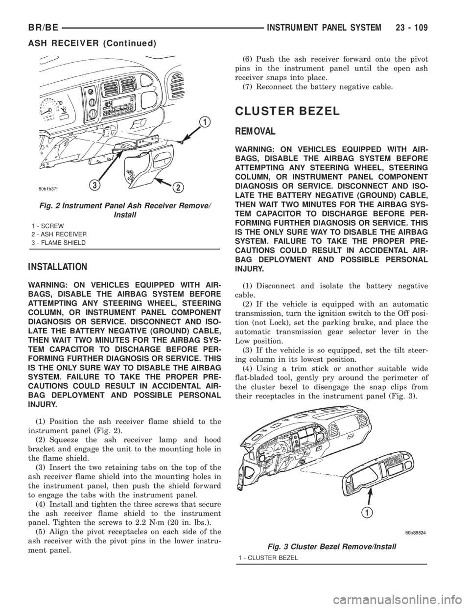
(1) Position the ash receiver flame shield to the
instrument panel (Fig. 2).
(2) Squeeze the ash receiver lamp and hood
bracket and engage the unit to the mounting hole in
the flame shield.
(3) Insert the two retaining tabs on the top of the
ash receiver flame shield into the mounting holes in
the instrument panel, then push the shield forward
to engage the tabs with the instrument panel.
(4) Install and tighten the three screws that secure
the ash receiver flame shield to the instrument
panel. Tighten the screws to 2.2 N´m (20 in. lbs.).
(5) Align the pivot receptacles on each side of the
ash receiver with the pivot pins in the lower instru-
ment panel.(6) Push the ash receiver forward onto the pivot
pins in the instrument panel until the open ash
receiver snaps into place.
(7) Reconnect the battery negative cable.
CLUSTER BEZEL
REMOVAL
WARNING: ON VEHICLES EQUIPPED WITH AIR-
BAGS, DISABLE THE AIRBAG SYSTEM BEFORE
ATTEMPTING ANY STEERING WHEEL, STEERING
COLUMN, OR INSTRUMENT PANEL COMPONENT
DIAGNOSIS OR SERVICE. DISCONNECT AND ISO-
LATE THE BATTERY NEGATIVE (GROUND) CABLE,
THEN WAIT TWO MINUTES FOR THE AIRBAG SYS-
TEM CAPACITOR TO DISCHARGE BEFORE PER-
FORMING FURTHER DIAGNOSIS OR SERVICE. THIS
IS THE ONLY SURE WAY TO DISABLE THE AIRBAG
SYSTEM. FAILURE TO TAKE THE PROPER PRE-
CAUTIONS COULD RESULT IN ACCIDENTAL AIR-
BAG DEPLOYMENT AND POSSIBLE PERSONAL
INJURY.
(1) Disconnect and isolate the battery negative
cable.
(2) If the vehicle is equipped with an automatic
transmission, turn the ignition switch to the Off posi-
tion (not Lock), set the parking brake, and place the
automatic transmission gear selector lever in the
Low position.
(3) If the vehicle is so equipped, set the tilt steer-
ing column in its lowest position.
(4) Using a trim stick or another suitable wide
flat-bladed tool, gently pry around the perimeter of
the cluster bezel to disengage the snap clips from
their receptacles in the instrument panel (Fig. 3).
Fig. 2 Instrument Panel Ash Receiver Remove/
Install
1 - SCREW
2 - ASH RECEIVER
3 - FLAME SHIELD
Fig. 3 Cluster Bezel Remove/Install
1 - CLUSTER BEZEL
BR/BEINSTRUMENT PANEL SYSTEM 23 - 109
ASH RECEIVER (Continued)