2001 DODGE RAM oil temperature
[x] Cancel search: oil temperaturePage 1472 of 2889
(3)Pre-lube the turbocharger.Pour 50 to 60 cc
(2 to 3 oz.) clean engine oil in the oil supply line fit-
ting. Carefully rotate the turbocharger impeller by
hand to distribute the oil thoroughly.
(4) Install and tighten the oil supply line fitting
nut to 20 N´m (133 in. lbs.) torque.
(5) Position the charge air cooler inlet pipe to the
turbocharger. With the clamp in position, tighten the
clamp nut to 11 N´m (95 in. lbs.) torque.
(6) Position the air inlet hose to the turbocharger
(Fig. 23). Tighten the clamp to 11 N´m (95 in. lbs.)
torque.
(7) Raise vehicle on hoist.
(8) Connect the exhaust pipe to the turbocharger
(Fig. 22) and tighten the bolts to 34 N´m (25 ft. lbs.)
torque.
(9) Lower the vehicle.
(10) Connect the battery negative cables.
(11) Start the engine to check for leaks.
CHARGE AIR COOLER AND
PLUMBING
DESCRIPTION
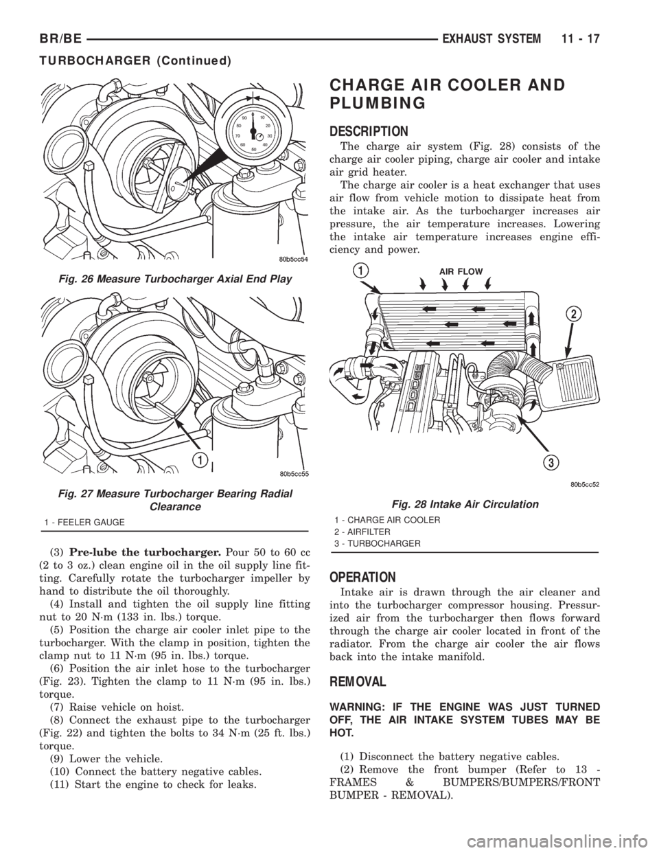
The charge air system (Fig. 28) consists of the
charge air cooler piping, charge air cooler and intake
air grid heater.
The charge air cooler is a heat exchanger that uses
air flow from vehicle motion to dissipate heat from
the intake air. As the turbocharger increases air
pressure, the air temperature increases. Lowering
the intake air temperature increases engine effi-
ciency and power.
OPERATION
Intake air is drawn through the air cleaner and
into the turbocharger compressor housing. Pressur-
ized air from the turbocharger then flows forward
through the charge air cooler located in front of the
radiator. From the charge air cooler the air flows
back into the intake manifold.
REMOVAL
WARNING: IF THE ENGINE WAS JUST TURNED
OFF, THE AIR INTAKE SYSTEM TUBES MAY BE
HOT.
(1) Disconnect the battery negative cables.
(2) Remove the front bumper (Refer to 13 -
FRAMES & BUMPERS/BUMPERS/FRONT
BUMPER - REMOVAL).
Fig. 26 Measure Turbocharger Axial End Play
Fig. 27 Measure Turbocharger Bearing Radial
Clearance
1 - FEELER GAUGE
Fig. 28 Intake Air Circulation
1 - CHARGE AIR COOLER
2 - AIRFILTER
3 - TURBOCHARGER
BR/BEEXHAUST SYSTEM 11 - 17
TURBOCHARGER (Continued)
Page 1504 of 2889
(7) 3.9L (V-6) engine only: Disconnect electrical
connector at intake manifold air temperature sensor.
Do not remove sensor.
(8) Disconnect fuel tube (line) at side of fuel rail.
Refer to Quick-Connect Fittings for procedures,
(9) Remove the remaining fuel rail mounting bolts.
(10) Gently rock and pull theleftfuel rail until
the fuel injectors just start to clear the intake mani-
fold. Gently rock and pull therightfuel rail until
the fuel injectors just start to clear the intake mani-
fold. Repeat this procedure (left/right) until all fuel
injectors have cleared the intake manifold.
(11) Remove fuel rail (with injectors attached)
from engine.
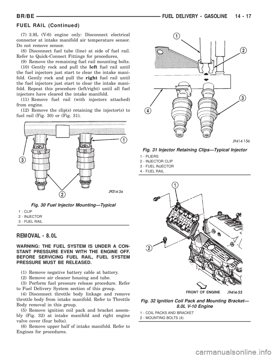
(12) Remove the clip(s) retaining the injector(s) to
fuel rail (Fig. 30) or (Fig. 31).
REMOVAL - 8.0L
WARNING: THE FUEL SYSTEM IS UNDER A CON-
STANT PRESSURE EVEN WITH THE ENGINE OFF.
BEFORE SERVICING FUEL RAIL, FUEL SYSTEM
PRESSURE MUST BE RELEASED.
(1) Remove negative battery cable at battery.
(2) Remove air cleaner housing and tube.
(3) Perform fuel pressure release procedure. Refer
to Fuel Delivery System section of this group.
(4) Disconnect throttle body linkage and remove
throttle body from intake manifold. Refer to Throttle
Body removal in this group.
(5) Remove ignition coil pack and bracket assem-
bly (Fig. 32) at intake manifold and right engine
valve cover (four bolts).
(6) Remove upper half of intake manifold. Refer to
Engines for procedures.
Fig. 30 Fuel Injector MountingÐTypical
1 - CLIP
2 - INJECTOR
3 - FUEL RAIL
Fig. 31 Injector Retaining ClipsÐTypical Injector
1 - PLIERS
2 - INJECTOR CLIP
3 - FUEL INJECTOR
4 - FUEL RAIL
Fig. 32 Ignition Coil Pack and Mounting BracketÐ
8.0L V-10 Engine
1 - COIL PACKS AND BRACKET
2 - MOUNTING BOLTS (4)
BR/BEFUEL DELIVERY - GASOLINE 14 - 17
FUEL RAIL (Continued)
Page 1505 of 2889
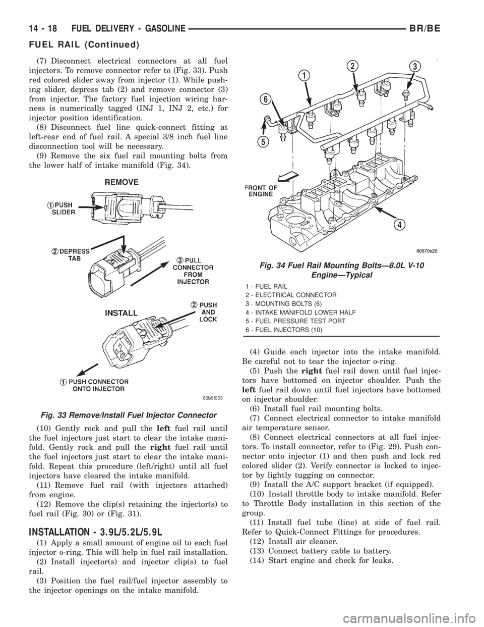
(7) Disconnect electrical connectors at all fuel
injectors. To remove connector refer to (Fig. 33). Push
red colored slider away from injector (1). While push-
ing slider, depress tab (2) and remove connector (3)
from injector. The factory fuel injection wiring har-
ness is numerically tagged (INJ 1, INJ 2, etc.) for
injector position identification.
(8) Disconnect fuel line quick-connect fitting at
left-rear end of fuel rail. A special 3/8 inch fuel line
disconnection tool will be necessary.
(9) Remove the six fuel rail mounting bolts from
the lower half of intake manifold (Fig. 34).
(10) Gently rock and pull theleftfuel rail until
the fuel injectors just start to clear the intake mani-
fold. Gently rock and pull therightfuel rail until
the fuel injectors just start to clear the intake mani-
fold. Repeat this procedure (left/right) until all fuel
injectors have cleared the intake manifold.
(11) Remove fuel rail (with injectors attached)
from engine.
(12) Remove the clip(s) retaining the injector(s) to
fuel rail (Fig. 30) or (Fig. 31).
INSTALLATION - 3.9L/5.2L/5.9L
(1) Apply a small amount of engine oil to each fuel
injector o-ring. This will help in fuel rail installation.
(2) Install injector(s) and injector clip(s) to fuel
rail.
(3) Position the fuel rail/fuel injector assembly to
the injector openings on the intake manifold.(4) Guide each injector into the intake manifold.
Be careful not to tear the injector o-ring.
(5) Push therightfuel rail down until fuel injec-
tors have bottomed on injector shoulder. Push the
leftfuel rail down until fuel injectors have bottomed
on injector shoulder.
(6) Install fuel rail mounting bolts.
(7) Connect electrical connector to intake manifold
air temperature sensor.
(8) Connect electrical connectors at all fuel injec-
tors. To install connector, refer to (Fig. 29). Push con-
nector onto injector (1) and then push and lock red
colored slider (2). Verify connector is locked to injec-
tor by lightly tugging on connector.
(9) Install the A/C support bracket (if equipped).
(10) Install throttle body to intake manifold. Refer
to Throttle Body installation in this section of the
group.
(11) Install fuel tube (line) at side of fuel rail.
Refer to Quick-Connect Fittings for procedures.
(12) Install air cleaner.
(13) Connect battery cable to battery.
(14) Start engine and check for leaks.
Fig. 33 Remove/Install Fuel Injector Connector
Fig. 34 Fuel Rail Mounting BoltsÐ8.0L V-10
EngineÐTypical
1 - FUEL RAIL
2 - ELECTRICAL CONNECTOR
3 - MOUNTING BOLTS (6)
4 - INTAKE MANIFOLD LOWER HALF
5 - FUEL PRESSURE TEST PORT
6 - FUEL INJECTORS (10)
14 - 18 FUEL DELIVERY - GASOLINEBR/BE
FUEL RAIL (Continued)
Page 1515 of 2889
FUEL INJECTION - GASOLINE
TABLE OF CONTENTS
page page
FUEL INJECTION - GASOLINE
DIAGNOSIS AND TESTING.................28
VISUAL INSPECTION - 3.9L/5.2L/5.9L
ENGINES.............................28
VISUAL INSPECTION - 8.0L ENGINE........32
SPECIFICATIONS........................35
SPECIAL TOOLS.........................36
ACCELERATOR PEDAL
REMOVAL..............................37
INSTALLATION...........................37
CRANKSHAFT POSITION SENSOR
DESCRIPTION...........................38
OPERATION.............................38
REMOVAL..............................39
INSTALLATION...........................40
FUEL PUMP RELAY
DESCRIPTION...........................41
OPERATION.............................41
REMOVAL..............................41
INSTALLATION...........................41
IDLE AIR CONTROL MOTOR
DESCRIPTION...........................41
OPERATION.............................41
REMOVAL..............................42
INSTALLATION...........................42
INTAKE AIR TEMPERATURE SENSOR
DESCRIPTION...........................43
OPERATION.............................43
REMOVAL..............................43
INSTALLATION...........................43
MANIFOLD ABSOLUTE PRESSURE SENSOR
DESCRIPTION...........................44OPERATION.............................44
REMOVAL..............................45
INSTALLATION...........................45
O2 SENSOR
DESCRIPTION...........................46
OPERATION.............................46
REMOVAL..............................47
INSTALLATION...........................48
PTO SWITCH
DESCRIPTION...........................48
OPERATION.............................48
THROTTLE BODY
DESCRIPTION...........................48
OPERATION.............................48
REMOVAL..............................48
INSTALLATION...........................49
THROTTLE CONTROL CABLE
REMOVAL..............................50
INSTALLATION...........................50
THROTTLE POSITION SENSOR
DESCRIPTION...........................51
OPERATION.............................51
REMOVAL..............................51
INSTALLATION...........................52
FUEL INJECTOR
DESCRIPTION...........................53
OPERATION.............................53
DIAGNOSIS AND TESTING.................53
FUEL INJECTOR TEST...................53
REMOVAL..............................53
INSTALLATION...........................53
FUEL INJECTION - GASOLINE
VISUAL INSPECTIONÐ3.9L/5.2L/5.9L
ENGINES
A visual inspection for loose, disconnected or incor-
rectly routed wires and hoses should be made. This
should be done before attempting to diagnose or ser-
vice the fuel injection system. A visual check will
help spot these faults and save unnecessary test and
diagnostic time. A thorough visual inspection will
include the following checks:
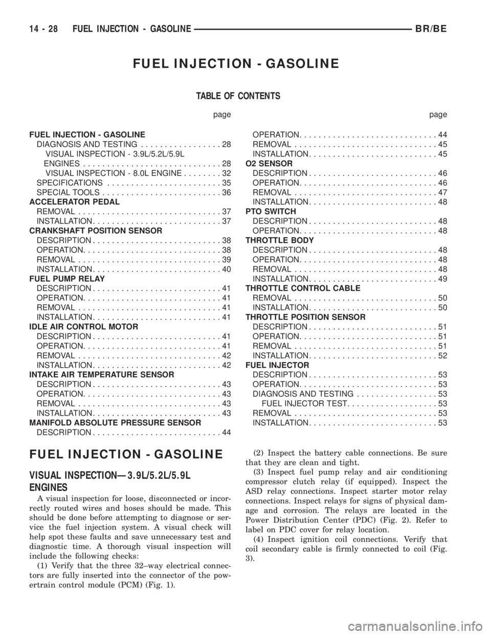
(1) Verify that the three 32±way electrical connec-
tors are fully inserted into the connector of the pow-
ertrain control module (PCM) (Fig. 1).(2) Inspect the battery cable connections. Be sure
that they are clean and tight.
(3) Inspect fuel pump relay and air conditioning
compressor clutch relay (if equipped). Inspect the
ASD relay connections. Inspect starter motor relay
connections. Inspect relays for signs of physical dam-
age and corrosion. The relays are located in the
Power Distribution Center (PDC) (Fig. 2). Refer to
label on PDC cover for relay location.
(4) Inspect ignition coil connections. Verify that
coil secondary cable is firmly connected to coil (Fig.
3).
14 - 28 FUEL INJECTION - GASOLINEBR/BE
Page 1533 of 2889
(3) Install MAP sensor mounting bolts (screws).
Tighten screws to 3 N´m (25 in. lbs.) torque.
(4) Install air cleaner.
INSTALLATION - 8.0L
The MAP sensor is mounted into the right upper
side of the intake manifold (Fig. 38). A rubber gasket
is used to seal the sensor to the intake manifold. The
rubber gasket is part of the sensor and is not ser-
viced separately.
(1) Check the condition of the sensor seal. Clean
the sensor and lubricate the rubber gasket with clean
engine oil.
(2) Clean the sensor opening in the intake mani-
fold.
(3) Install the sensor into the intake manifold.
(4) Install sensor mounting bolts. Tighten bolts to
2 N´m (20 in. lbs.) torque.
(5) Install the electrical connector to sensor.
O2 SENSOR
DESCRIPTION
The Oxygen Sensors (O2S) are attached to, and
protrude into the vehicle exhaust system. Depending
on the emission package, the vehicle may use a total
of either 2 or 4 sensors.
3.9L/5.2L/Light Duty 5.9L Engine:Four sensors
are used: 2 upstream (referred to as 1/1 and 2/1) and
2 downstream (referred to as 1/2 and 2/2). With this
emission package, the right upstream sensor (2/1) is
located in the right exhaust downpipe just before the
mini-catalytic convertor. The left upstream sensor
(1/1) is located in the left exhaust downpipe just
before the mini-catalytic convertor. The right down-
stream sensor (2/2) is located in the right exhaust
downpipe just after the mini-catalytic convertor, and
before the main catalytic convertor. The left down-
stream sensor (1/2) is located in the left exhaust
downpipe just after the mini-catalytic convertor, and
before the main catalytic convertor.
Medium and Heavy Duty 8.0L V-10 Engine:
Four sensors are used (2 upstream, 1 pre-catalyst
and 1 post-catalyst). With this emission package, the
1/1 upstream sensor (left side) is located in the left
exhaust downpipe before both the pre-catalyst sensor
(1/2), and the main catalytic convertor. The 2/1
upstream sensor (right side) is located in the right
exhaust downpipe before both the pre-catalyst sensor
(1/2), and the main catalytic convertor. The pre-cata-
lyst sensor (1/2) is located after the 1/1 and 2/1 sen-
sors, and just before the main catalytic convertor.
The post-catalyst sensor (1/3) is located just after the
main catalytic convertor.Heavy Duty 5.9L Engine:Two sensors are used.
They arebothreferred to as upstream sensors (left
side is referred to as 1/1 and right side is referred to
as 2/1). With this emission package, a sensor is
located in each of the exhaust downpipes before the
main catalytic convertor.
OPERATION
An O2 sensor is a galvanic battery that provides
the PCM with a voltage signal (0-1 volt) inversely
proportional to the amount of oxygen in the exhaust.
In other words, if the oxygen content is low, the volt-
age output is high; if the oxygen content is high the
output voltage is low. The PCM uses this information
to adjust injector pulse-width to achieve the
14.7±to±1 air/fuel ratio necessary for proper engine
operation and to control emissions.
The O2 sensor must have a source of oxygen from
outside of the exhaust stream for comparison. Cur-
rent O2 sensors receive their fresh oxygen (outside
air) supply through the wire harness. This is why it
is important to never solder an O2 sensor connector,
or pack the connector with grease.
Four wires (circuits) are used on each O2 sensor: a
12±volt feed circuit for the sensor heating element; a
ground circuit for the heater element; a low-noise
sensor return circuit to the PCM, and an input cir-
cuit from the sensor back to the PCM to detect sen-
sor operation.
Oxygen Sensor Heaters/Heater Relays:
Depending on the emissions package, the heating ele-
ments within the sensors will be supplied voltage
from either the ASD relay, or 2 separate oxygen sen-
sor relays. Refer to 8, Wiring Diagrams to determine
which relays are used.
The O2 sensor uses a Positive Thermal Co-efficient
(PTC) heater element. As temperature increases,
resistance increases. At ambient temperatures
around 70ÉF, the resistance of the heating element is
approximately 4.5 ohms. As the sensor's temperature
increases, resistance in the heater element increases.
This allows the heater to maintain the optimum
operating temperature of approximately 930É-1100ÉF
(500É-600É C). Although the sensors operate the
same, there are physical differences, due to the envi-
ronment that they operate in, that keep them from
being interchangeable.
Maintaining correct sensor temperature at all times
allows the system to enter into closed loop operation
sooner. Also, it allows the system to remain in closed
loop operation during periods of extended idle.
In Closed Loop operation, the PCM monitors cer-
tain O2 sensor input(s) along with other inputs, and
adjusts the injector pulse width accordingly. During
Open Loop operation, the PCM ignores the O2 sensor
input. The PCM adjusts injector pulse width based
14 - 46 FUEL INJECTION - GASOLINEBR/BE
MANIFOLD ABSOLUTE PRESSURE SENSOR (Continued)
Page 1542 of 2889
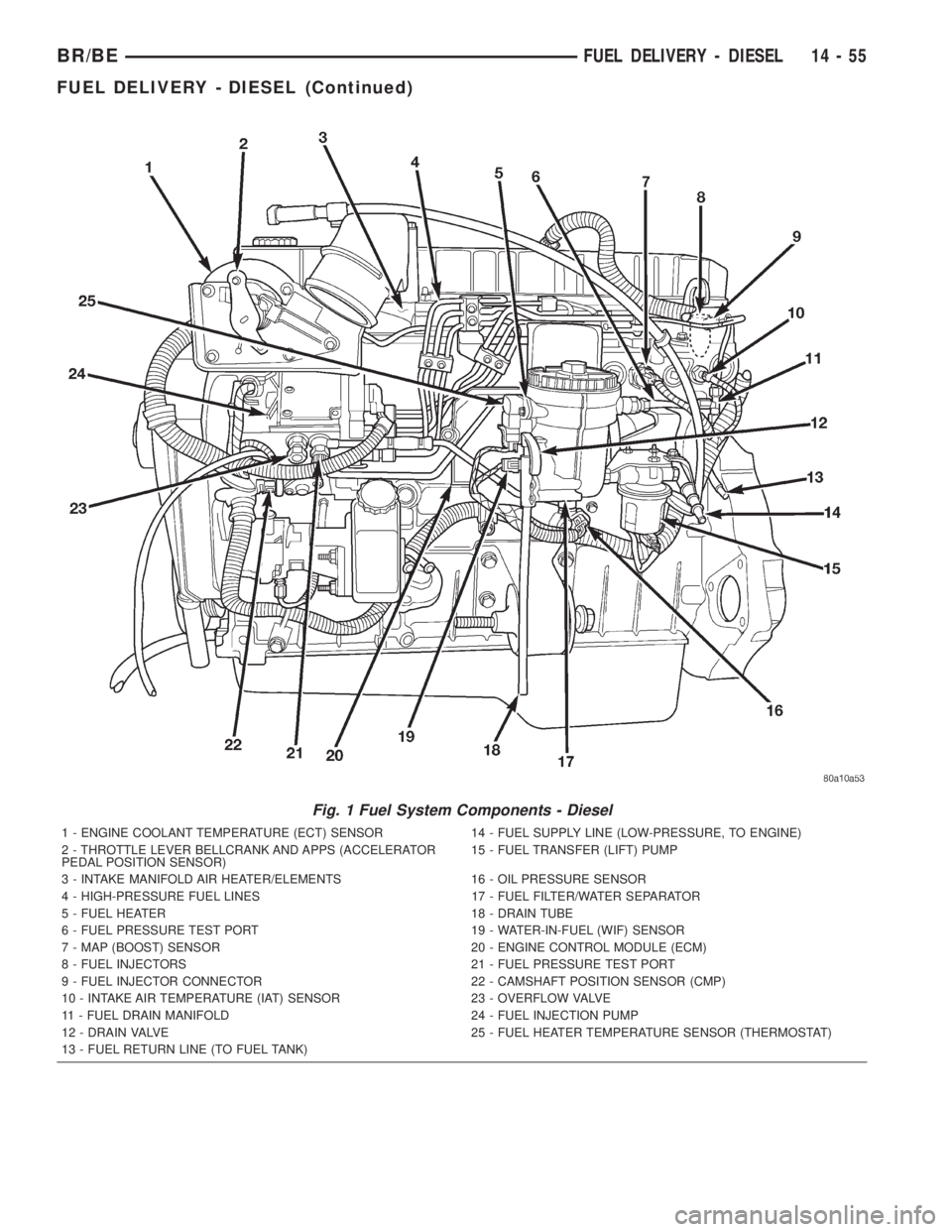
Fig. 1 Fuel System Components - Diesel
1 - ENGINE COOLANT TEMPERATURE (ECT) SENSOR 14 - FUEL SUPPLY LINE (LOW-PRESSURE, TO ENGINE)
2 - THROTTLE LEVER BELLCRANK AND APPS (ACCELERATOR
PEDAL POSITION SENSOR)15 - FUEL TRANSFER (LIFT) PUMP
3 - INTAKE MANIFOLD AIR HEATER/ELEMENTS 16 - OIL PRESSURE SENSOR
4 - HIGH-PRESSURE FUEL LINES 17 - FUEL FILTER/WATER SEPARATOR
5 - FUEL HEATER 18 - DRAIN TUBE
6 - FUEL PRESSURE TEST PORT 19 - WATER-IN-FUEL (WIF) SENSOR
7 - MAP (BOOST) SENSOR 20 - ENGINE CONTROL MODULE (ECM)
8 - FUEL INJECTORS 21 - FUEL PRESSURE TEST PORT
9 - FUEL INJECTOR CONNECTOR 22 - CAMSHAFT POSITION SENSOR (CMP)
10 - INTAKE AIR TEMPERATURE (IAT) SENSOR 23 - OVERFLOW VALVE
11 - FUEL DRAIN MANIFOLD 24 - FUEL INJECTION PUMP
12 - DRAIN VALVE 25 - FUEL HEATER TEMPERATURE SENSOR (THERMOSTAT)
13 - FUEL RETURN LINE (TO FUEL TANK)
BR/BEFUEL DELIVERY - DIESEL 14 - 55
FUEL DELIVERY - DIESEL (Continued)
Page 1548 of 2889
(c) Check condition of o-ring.(d) Inspect the 2 WIF sensor probes. Carefully
clean contaminants from sensor probes with a cloth
if necessary. Replace sensor if probes are covered
with contaminants and will not clean up.
(7)Fuel Heater Element Replacement:The
heater element is located in the fuel filter housing
(Fig. 6).
(a) Remove fuel filter. See previous steps.
(b) Disconnect electrical connector from fuel tem-
perature sensor housing at side of fuel filter hous-
ing (Fig. 8).
(c) Remove 2 temperature sensor housing
mounting screws and carefully remove sensor
housing from fuel filter housing.
(d) Pry round wiring connector from fuel filter
housing and heater element. This connector passes
through the fuel filter housing and is plugged
directly into the heater element.
(e) Unlock heater element fingers and pry heater
element from filter housing.
(8)Drain Valve Replacement:The drain valve is
located on the side of the fuel filter housing (Fig. 6).
(a) Disconnect drain hose (Fig. 5) at bottom of
drain valve.
(b) Remove 4 drain valve mounting screws.
(c) Remove drain valve from filter housing.
(d) Remove 2 drain valve o-rings from filter
housing.
INSTALLATION
Refer to maintenance schedules in this manual for
recommended fuel filter replacement intervals.
(1) Thoroughly clean inside of filter housing, filter
cap and all related components.
(2)Fuel Filter:
(a) Fill fuel filter housing with clean diesel fuel.
If filter housing (canister) is not filled with
clean diesel fuel before installation, manual
air bleeding of fuel system may be necessary
(temporary rough engine running may occur).
If necessary, refer to Air Bleed Procedures.
(b) Snap new filter into locking fingers on cap.
Hole in filter should face downward.
(c) Install new o-ring to cap.
(d) Apply a light film of clean diesel oil to cap
o-ring seal.
(e) Load filter and cap into housing.
(f) Tighten cap to 25 ft. lbs. torque. Do not over-
tighten cap.
(3)Water-In-Fuel (WIF) Sensor:
(a) Install new o-ring seal to WIF sensor.
(b) Apply a light film of clean diesel oil to o-ring
seal.
(c) Install sensor into housing.
(d) Tighten sensor to 2±3 N´m (15±20 in. lbs.)
torque.
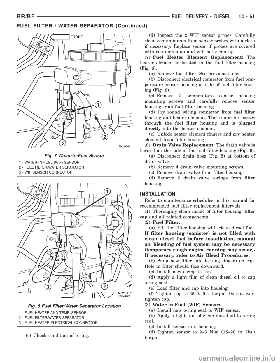
Fig. 7 Water-In-Fuel Sensor
1 - WATER-IN-FUEL (WIF) SENSOR
2 - FUEL FILTER/WATER SEPARATOR
3 - WIF SENSOR CONNECTOR
Fig. 8 Fuel Filter/Water Separator Location
1 - FUEL HEATER AND TEMP. SENSOR
2 - FUEL FILTER/WATER SEPARATOR
3 - FUEL HEATER ELECTRICAL CONNECTOR
BR/BEFUEL DELIVERY - DIESEL 14 - 61
FUEL FILTER / WATER SEPARATOR (Continued)
Page 1549 of 2889
(e) Connect electrical connector to WIF sensor.
(f) Install fuel filter. Refer to previous steps.
(4)Fuel Heater Element:
(a) Do not install fuel filter until heater element
is installed.
(b) Position heater element into filter housing
(fingers downward). Lock fingers into housing.
(c) Install new o-ring to electrical connector
(where connector passes through filter housing).
Apply a light film of clean diesel oil to o-ring seal.
Press this connector into filter housing until it
snaps into heater element.
(d) Install temperature sensor housing and 2
mounting screws to fuel filter housing.
(e) Connect electrical connector.
(f) Install fuel filter. Refer to previous steps.
(5)Drain Valve:
(a) Install 2 new o-rings to valve and filter hous-
ing.
(b) Apply a light film of clean diesel oil to both
seals.
(c) Position valve to filter housing.
(d) Install 4 mounting screws and tighten to 3±5
N´m (30±40 in. lbs.) torque.
(e) Connect drain hose to drain valve.
(f) Install fuel filter. Refer to previous steps.
(6) Start engine and check for leaks.
FUEL HEATER
DESCRIPTION
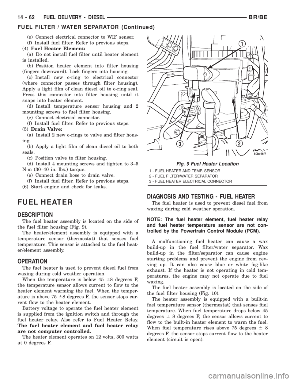
The fuel heater assembly is located on the side of
the fuel filter housing (Fig. 9).
The heater/element assembly is equipped with a
temperature sensor (thermostat) that senses fuel
temperature. This sensor is attached to the fuel heat-
er/element assembly.
OPERATION
The fuel heater is used to prevent diesel fuel from
waxing during cold weather operation.
When the temperature is below 4568 degrees F,
the temperature sensor allows current to flow to the
heater element warming the fuel. When the temper-
ature is above 7568 degrees F, the sensor stops cur-
rent flow to the heater element.
Battery voltage to operate the fuel heater element
is supplied from the ignition switch and through the
fuel heater relay. Also refer to Fuel Heater Relay.
The fuel heater element and fuel heater relay
are not computer controlled.
The heater element operates on 12 volts, 300 watts
at 0 degrees F.
DIAGNOSIS AND TESTING - FUEL HEATER
The fuel heater is used to prevent diesel fuel from
waxing during cold weather operation.
NOTE: The fuel heater element, fuel heater relay
and fuel heater temperature sensor are not con-
trolled by the Powertrain Control Module (PCM).
A malfunctioning fuel heater can cause a wax
build-up in the fuel filter/water separator. Wax
build-up in the filter/separator can cause engine
starting problems and prevent the engine from rev-
ving up. It can also cause blue or white fog-like
exhaust. If the heater is not operating in cold tem-
peratures, the engine may not operate due to fuel
waxing.
The fuel heater assembly is located on the side of
the fuel filter housing (Fig. 10).
The heater assembly is equipped with a built-in
fuel temperature sensor (thermostat) that senses fuel
temperature. When fuel temperature drops below 45
degrees68 degrees F, the sensor allows current to
flow to the built-in heater element to warm the fuel.
When fuel temperature rises above 75 degrees68
degrees F, the sensor stops current flow to the heater
element (circuit is open).
Fig. 9 Fuel Heater Location
1 - FUEL HEATER AND TEMP. SENSOR
2 - FUEL FILTER/WATER SEPARATOR
3 - FUEL HEATER ELECTRICAL CONNECTOR
14 - 62 FUEL DELIVERY - DIESELBR/BE
FUEL FILTER / WATER SEPARATOR (Continued)