2001 DODGE RAM airbag disable
[x] Cancel search: airbag disablePage 2764 of 2889

(3) Disengage the demister tubes from each end of
the main demister duct.
(4) Remove the defroster and demister duct unit
from the instrument panel.
REMOVAL - DEFROSTER AND DEMISTER
DUCT ADAPTER
(1) Roll the instrument panel assembly down, but
do not remove it from the vehicle. Refer to Instru-
ment Panel System for the procedures.
(2)
Using a trim stick or another suitable wide flat-
bladed tool, gently pry at the perimeter edges of the
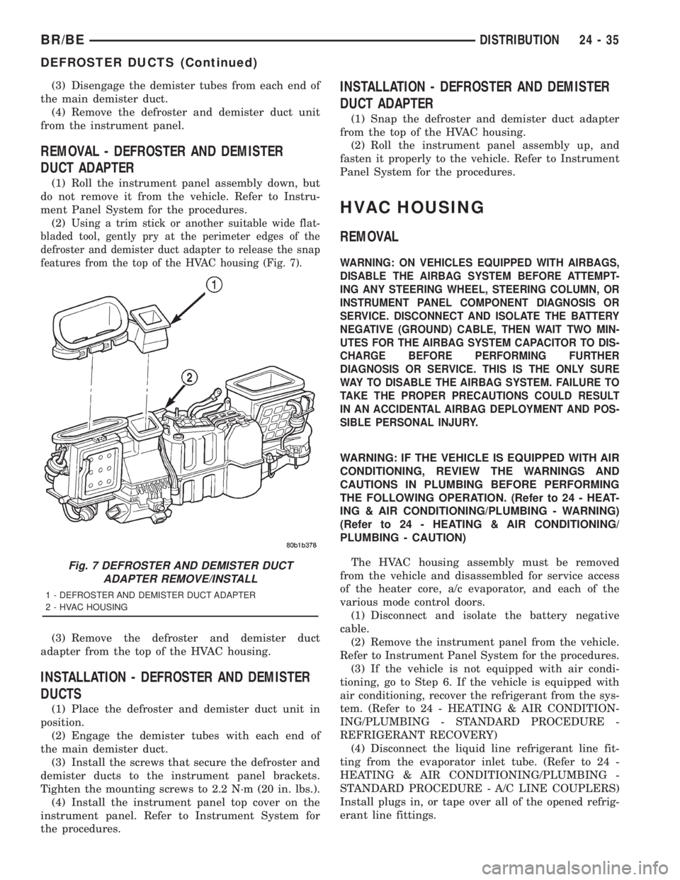
defroster and demister duct adapter to release the snap
features from the top of the HVAC housing (Fig. 7).
(3) Remove the defroster and demister duct
adapter from the top of the HVAC housing.
INSTALLATION - DEFROSTER AND DEMISTER
DUCTS
(1) Place the defroster and demister duct unit in
position.
(2) Engage the demister tubes with each end of
the main demister duct.
(3) Install the screws that secure the defroster and
demister ducts to the instrument panel brackets.
Tighten the mounting screws to 2.2 N´m (20 in. lbs.).
(4) Install the instrument panel top cover on the
instrument panel. Refer to Instrument System for
the procedures.
INSTALLATION - DEFROSTER AND DEMISTER
DUCT ADAPTER
(1) Snap the defroster and demister duct adapter
from the top of the HVAC housing.
(2) Roll the instrument panel assembly up, and
fasten it properly to the vehicle. Refer to Instrument
Panel System for the procedures.
HVAC HOUSING
REMOVAL
WARNING: ON VEHICLES EQUIPPED WITH AIRBAGS,
DISABLE THE AIRBAG SYSTEM BEFORE ATTEMPT-
ING ANY STEERING WHEEL, STEERING COLUMN, OR
INSTRUMENT PANEL COMPONENT DIAGNOSIS OR
SERVICE. DISCONNECT AND ISOLATE THE BATTERY
NEGATIVE (GROUND) CABLE, THEN WAIT TWO MIN-
UTES FOR THE AIRBAG SYSTEM CAPACITOR TO DIS-
CHARGE BEFORE PERFORMING FURTHER
DIAGNOSIS OR SERVICE. THIS IS THE ONLY SURE
WAY TO DISABLE THE AIRBAG SYSTEM. FAILURE TO
TAKE THE PROPER PRECAUTIONS COULD RESULT
IN AN ACCIDENTAL AIRBAG DEPLOYMENT AND POS-
SIBLE PERSONAL INJURY.
WARNING: IF THE VEHICLE IS EQUIPPED WITH AIR
CONDITIONING, REVIEW THE WARNINGS AND
CAUTIONS IN PLUMBING BEFORE PERFORMING
THE FOLLOWING OPERATION. (Refer to 24 - HEAT-
ING & AIR CONDITIONING/PLUMBING - WARNING)
(Refer to 24 - HEATING & AIR CONDITIONING/
PLUMBING - CAUTION)
The HVAC housing assembly must be removed
from the vehicle and disassembled for service access
of the heater core, a/c evaporator, and each of the
various mode control doors.
(1) Disconnect and isolate the battery negative
cable.
(2) Remove the instrument panel from the vehicle.
Refer to Instrument Panel System for the procedures.
(3) If the vehicle is not equipped with air condi-
tioning, go to Step 6. If the vehicle is equipped with
air conditioning, recover the refrigerant from the sys-
tem. (Refer to 24 - HEATING & AIR CONDITION-
ING/PLUMBING - STANDARD PROCEDURE -
REFRIGERANT RECOVERY)
(4) Disconnect the liquid line refrigerant line fit-
ting from the evaporator inlet tube. (Refer to 24 -
HEATING & AIR CONDITIONING/PLUMBING -
STANDARD PROCEDURE - A/C LINE COUPLERS)
Install plugs in, or tape over all of the opened refrig-
erant line fittings.
Fig. 7 DEFROSTER AND DEMISTER DUCT
ADAPTER REMOVE/INSTALL
1 - DEFROSTER AND DEMISTER DUCT ADAPTER
2 - HVAC HOUSING
BR/BEDISTRIBUTION 24 - 35
DEFROSTER DUCTS (Continued)
Page 2767 of 2889

BLEND DOOR
REMOVAL
(1) Remove the HVAC housing from the vehicle,
and disassemble the housing halves. (Refer to 24 -
HEATING & AIR CONDITIONING/DISTRIBUTION/
HVAC HOUSING - REMOVAL) (Refer to 24 - HEAT-
ING & AIR CONDITIONING/DISTRIBUTION/HVAC
HOUSING - DISASSEMBLY)
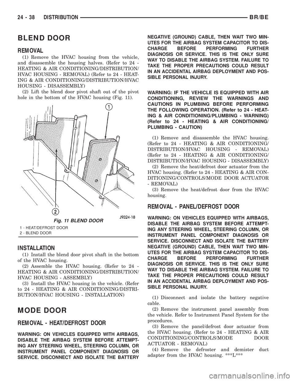
(2) Lift the blend door pivot shaft out of the pivot
hole in the bottom of the HVAC housing (Fig. 11).
INSTALLATION
(1) Install the blend door pivot shaft in the bottom
of the HVAC housing.
(2) Assemble the HVAC housing. (Refer to 24 -
HEATING & AIR CONDITIONING/DISTRIBUTION/
HVAC HOUSING - ASSEMBLY)
(3) Install the HVAC housing in the vehicle. (Refer
to 24 - HEATING & AIR CONDITIONING/DISTRI-
BUTION/HVAC HOUSING - INSTALLATION)
MODE DOOR
REMOVAL - HEAT/DEFROST DOOR
WARNING: ON VEHICLES EQUIPPED WITH AIRBAGS,
DISABLE THE AIRBAG SYSTEM BEFORE ATTEMPT-
ING ANY STEERING WHEEL, STEERING COLUMN, OR
INSTRUMENT PANEL COMPONENT DIAGNOSIS OR
SERVICE. DISCONNECT AND ISOLATE THE BATTERYNEGATIVE (GROUND) CABLE, THEN WAIT TWO MIN-
UTES FOR THE AIRBAG SYSTEM CAPACITOR TO DIS-
CHARGE BEFORE PERFORMING FURTHER
DIAGNOSIS OR SERVICE. THIS IS THE ONLY SURE
WAY TO DISABLE THE AIRBAG SYSTEM. FAILURE TO
TAKE THE PROPER PRECAUTIONS COULD RESULT
IN AN ACCIDENTAL AIRBAG DEPLOYMENT AND POS-
SIBLE PERSONAL INJURY.
WARNING: IF THE VEHICLE IS EQUIPPED WITH AIR
CONDITIONING, REVIEW THE WARNINGS AND
CAUTIONS IN PLUMBING BEFORE PERFORMING
THE FOLLOWING OPERATION. (Refer to 24 - HEAT-
ING & AIR CONDITIONING/PLUMBING - WARNING)
(Refer to 24 - HEATING & AIR CONDITIONING/
PLUMBING - CAUTION)
(1) Remove and disassemble the HVAC housing.
(Refer to 24 - HEATING & AIR CONDITIONING/
DISTRIBUTION/HVAC HOUSING - REMOVAL)
(Refer to 24 - HEATING & AIR CONDITIONING/
DISTRIBUTION/HVAC HOUSING - DISASSEMBLY)
(2) Remove the heat/defrost door actuator from the
HVAC housing. (Refer to 24 - HEATING & AIR CON-
DITIONING/CONTROLS/MODE DOOR ACTUATOR
- REMOVAL)
(3) Remove the heat/defrost door from the HVAC
housing.
REMOVAL - PANEL/DEFROST DOOR
WARNING: ON VEHICLES EQUIPPED WITH AIRBAGS,
DISABLE THE AIRBAG SYSTEM BEFORE ATTEMPT-
ING ANY STEERING WHEEL, STEERING COLUMN, OR
INSTRUMENT PANEL COMPONENT DIAGNOSIS OR
SERVICE. DISCONNECT AND ISOLATE THE BATTERY
NEGATIVE (GROUND) CABLE, THEN WAIT TWO MIN-
UTES FOR THE AIRBAG SYSTEM CAPACITOR TO DIS-
CHARGE BEFORE PERFORMING FURTHER
DIAGNOSIS OR SERVICE. THIS IS THE ONLY SURE
WAY TO DISABLE THE AIRBAG SYSTEM. FAILURE TO
TAKE THE PROPER PRECAUTIONS COULD RESULT
IN AN ACCIDENTAL AIRBAG DEPLOYMENT AND POS-
SIBLE PERSONAL INJURY.
(1) Disconnect and isolate the battery negative
cable.
(2) Remove the instrument panel assembly from
the vehicle. Refer to Instrument Panel System for the
procedures.
(3) Remove the panel/defrost door actuator from
the HVAC housing. (Refer to 24 - HEATING & AIR
CONDITIONING/CONTROLS/MODE DOOR
ACTUATOR - REMOVAL)
(4) Remove the defroster and demister duct
adapter from the HVAC housing. ***L***
Fig. 11 BLEND DOOR
1 - HEAT/DEFROST DOOR
2 - BLEND DOOR
24 - 38 DISTRIBUTIONBR/BE
Page 2768 of 2889

(5) Lift the panel/defrost door out of the top open-
ing of the HVAC housing.
INSTALLATION - HEAT/DEFROST DOOR
(1) Install the heat/defrost door in the HVAC hous-
ing.
(2) Assemble the HVAC housing. (Refer to 24 -
HEATING & AIR CONDITIONING/DISTRIBUTION/
HVAC HOUSING - ASSEMBLY)
(3) Install the heat/defrost door actuator on the
HVAC housing. (Refer to 24 - HEATING & AIR CON-
DITIONING/CONTROLS/MODE DOOR ACTUATOR
- INSTALLATION)
(4) Install the HVAC housing in the vehicle. (Refer
to 24 - HEATING & AIR CONDITIONING/DISTRI-
BUTION/HVAC HOUSING - INSTALLATION)
INSTALLATION - PANEL/DEFROST DOOR
(1) Install the panel/defrost door through the top
opening of the HVAC housing.
(2) Install the defroster and demister duct adapter
on the HVAC housing. (Refer to 24 - HEATING &
AIR CONDITIONING/DISTRIBUTION/DEFROSTER
DUCTS - INSTALLATION)
(3) Install the panel/defrost door actuator on the
HVAC housing. (Refer to 24 - HEATING & AIR CON-
DITIONING/CONTROLS/MODE DOOR ACTUATOR
- REMOVAL)
(4) Install the instrument panel assembly in the
vehicle. Refer to Instrument Panel System for the
procedures.
(5) Connect the battery negative cable.
RECIRCULATION DOOR
REMOVAL
WARNING: ON VEHICLES EQUIPPED WITH AIR-
BAGS, DISABLE THE AIRBAG SYSTEM BEFORE
ATTEMPTING ANY STEERING WHEEL, STEERING
COLUMN, OR INSTRUMENT PANEL COMPONENT
DIAGNOSIS OR SERVICE. DISCONNECT AND ISO-
LATE THE BATTERY NEGATIVE (GROUND) CABLE,
THEN WAIT TWO MINUTES FOR THE AIRBAG SYS-
TEM CAPACITOR TO DISCHARGE BEFORE PER-FORMING FURTHER DIAGNOSIS OR SERVICE. THIS
IS THE ONLY SURE WAY TO DISABLE THE AIRBAG
SYSTEM. FAILURE TO TAKE THE PROPER PRE-
CAUTIONS COULD RESULT IN AN ACCIDENTAL
AIRBAG DEPLOYMENT AND POSSIBLE PERSONAL
INJURY.
WARNING: IF THE VEHICLE IS EQUIPPED WITH AIR
CONDITIONING, REVIEW THE WARNINGS AND
CAUTIONS IN PLUMBING BEFORE PERFORMING
THE FOLLOWING OPERATION. (Refer to 24 - HEAT-
ING & AIR CONDITIONING/PLUMBING - WARNING)
(Refer to 24 - HEATING & AIR CONDITIONING/
PLUMBING - CAUTION)
(1) Remove the HVAC housing from the vehicle.
(Refer to 24 - HEATING & AIR CONDITIONING/
DISTRIBUTION/HVAC HOUSING - REMOVAL)
(2) Unsnap the recirculation door vacuum actuator
link clip and disengage the link from the recircula-
tion door lever. (Refer to 24 - HEATING & AIR CON-
DITIONING/CONTROLS/RECIRCULATION DOOR
ACTUATOR - REMOVAL)
(3) Using a trim stick or another suitable wide
flat-bladed tool, gently pry the retainer off of the
recirculation door pivot shaft.
(4) Remove the recirculation door through the out-
side air intake opening on the top of the HVAC hous-
ing.
INSTALLATION
(1) Install the recirculation door through the out-
side air intake opening on the top of the HVAC hous-
ing.
(2) Install the retainer on the recirculation door
pivot shaft.
(3) Engage the recirculation door vacuum actuator
link clip with the recirculation door lever. (Refer to
24 - HEATING & AIR CONDITIONING/CONTROLS/
RECIRCULATION DOOR ACTUATOR - INSTALLA-
TION)
(4) Install the HVAC housing in the vehicle. (Refer
to 24 - HEATING & AIR CONDITIONING/DISTRI-
BUTION/HVAC HOUSING - INSTALLATION)
BR/BEDISTRIBUTION 24 - 39
MODE DOOR (Continued)