2001 CHRYSLER VOYAGER recommended oil
[x] Cancel search: recommended oilPage 3250 of 4284
The engagement and disengagement of the TCC
are automatic and controlled by the Powertrain Con-
trol Module (PCM). The engagement cannot be acti-
vated in the lower gears because it eliminates the
torque multiplication effect of the torque converter
necessary for acceleration. Inputs that determine
clutch engagement are: coolant temperature, vehicle
speed and throttle position. The torque converter
clutch is engaged by the clutch solenoid on the valve
body. The clutch will engage at approximately 56
km/h (35 mph) with light throttle, after the shift to
third gear.
REMOVAL
NOTE: If torque conveter assembly is being
replaced, it is necessary to restart the TCC Break-In
Strategy. (Refer to 8 - ELECTRICAL/ELECTRONIC
CONTROL MODULES/TRANSMISSION CONTROL
MODULE - STANDARD PROCEDURE)
(1) Remove transmission and torque converter
from vehicle. (Refer to 21 - TRANSMISSION/TRANS-
AXLE/AUTOMATIC - 41TE - REMOVAL)
(2) Place a suitable drain pan under the converter
housing end of the transmission.
CAUTION: Verify that transmission is secure on the
lifting device or work surface, the center of gravity
of the transmission will shift when the torque con-
verter is removed creating an unstable condition.
The torque converter is a heavy unit. Use caution
when separating the torque converter from the
transmission.
(3) Pull the torque converter forward until the cen-
ter hub clears the oil pump seal.
(4) Separate the torque converter from the trans-
mission.
INSTALLATION
NOTE: If torque conveter is being replaced, it is
necessary to restart the TCC Break-In Strategy.
(Refer to 8 - ELECTRICAL/ELECTRONIC CONTROL
MODULES/TRANSMISSION CONTROL MODULE -
STANDARD PROCEDURE)
Check converter hub and drive notches for sharp
edges, burrs, scratches, or nicks. Polish the hub and
notches with 320/400 grit paper or crocus cloth if nec-
essary. The hub must be smooth to avoid damaging
the pump seal at installation.
(1) Lubricate converter hub and oil pump seal lip
with transmission fluid.
(2) Place torque converter in position on transmis-
sion.CAUTION: Do not damage oil pump seal or bushing
while inserting torque converter into the front of the
transmission.
(3) Align torque converter to oil pump seal open-
ing.
(4) Insert torque converter hub into oil pump.
(5) While pushing torque converter inward, rotate
converter until converter is fully seated in the oil
pump gears.
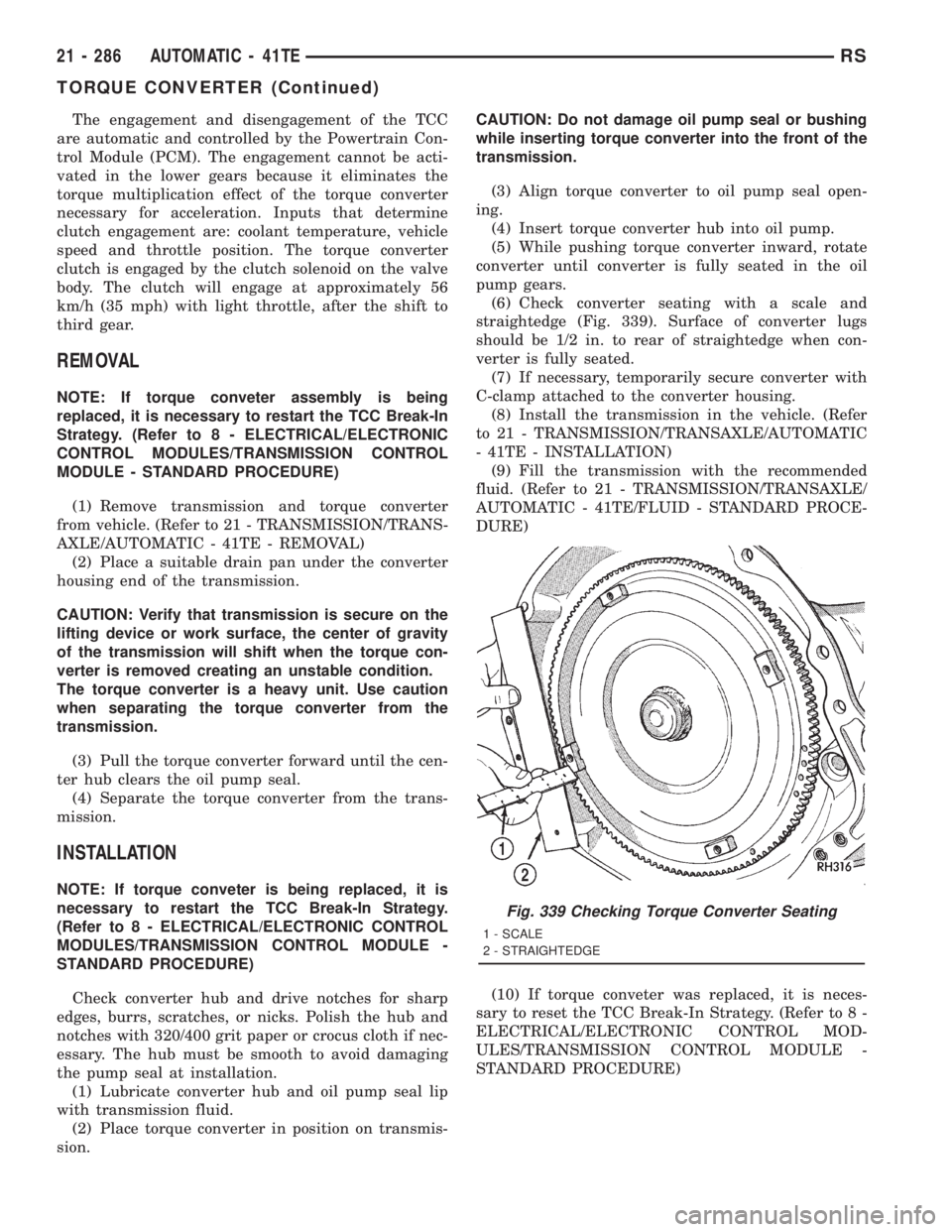
(6) Check converter seating with a scale and
straightedge (Fig. 339). Surface of converter lugs
should be 1/2 in. to rear of straightedge when con-
verter is fully seated.
(7) If necessary, temporarily secure converter with
C-clamp attached to the converter housing.
(8) Install the transmission in the vehicle. (Refer
to 21 - TRANSMISSION/TRANSAXLE/AUTOMATIC
- 41TE - INSTALLATION)
(9) Fill the transmission with the recommended
fluid. (Refer to 21 - TRANSMISSION/TRANSAXLE/
AUTOMATIC - 41TE/FLUID - STANDARD PROCE-
DURE)
(10) If torque conveter was replaced, it is neces-
sary to reset the TCC Break-In Strategy. (Refer to 8 -
ELECTRICAL/ELECTRONIC CONTROL MOD-
ULES/TRANSMISSION CONTROL MODULE -
STANDARD PROCEDURE)
Fig. 339 Checking Torque Converter Seating
1 - SCALE
2 - STRAIGHTEDGE
21 - 286 AUTOMATIC - 41TERS
TORQUE CONVERTER (Continued)
Page 3375 of 4284
CLEANING - TIRES
Before delivery of a vehicle, remove the protective
coating on the tires with white sidewalls or raised
white letters. To remove the protective coating, apply
warm water and let it soak for a few minutes. After-
wards, scrub the coating away with a soft bristle
brush. Steam cleaning may also be used to remove
the coating.
CAUTION: DO NOT use gasoline, mineral oil, oil-
based solvent or a wire brush for cleaning.
WHEELS
DESCRIPTION - WHEEL
Original equipment wheels are designed for proper
operation at all loads up to the specified maximum
vehicle capacity.
All models use either steel or aluminum drop-cen-
ter wheels. Every wheel has raised sections between
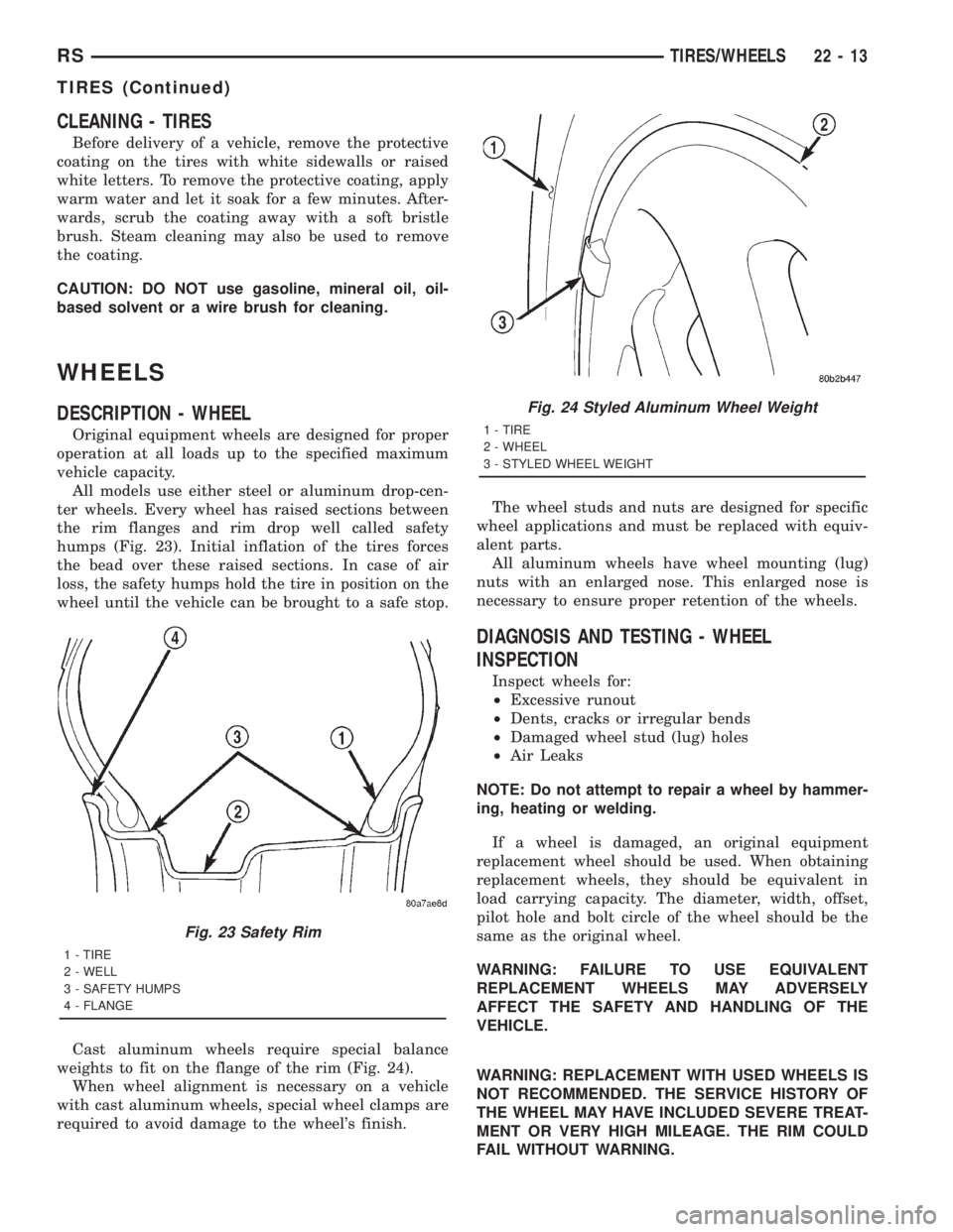
the rim flanges and rim drop well called safety
humps (Fig. 23). Initial inflation of the tires forces
the bead over these raised sections. In case of air
loss, the safety humps hold the tire in position on the
wheel until the vehicle can be brought to a safe stop.
Cast aluminum wheels require special balance
weights to fit on the flange of the rim (Fig. 24).
When wheel alignment is necessary on a vehicle
with cast aluminum wheels, special wheel clamps are
required to avoid damage to the wheel's finish.The wheel studs and nuts are designed for specific
wheel applications and must be replaced with equiv-
alent parts.
All aluminum wheels have wheel mounting (lug)
nuts with an enlarged nose. This enlarged nose is
necessary to ensure proper retention of the wheels.
DIAGNOSIS AND TESTING - WHEEL
INSPECTION
Inspect wheels for:
²Excessive runout
²Dents, cracks or irregular bends
²Damaged wheel stud (lug) holes
²Air Leaks
NOTE: Do not attempt to repair a wheel by hammer-
ing, heating or welding.
If a wheel is damaged, an original equipment
replacement wheel should be used. When obtaining
replacement wheels, they should be equivalent in
load carrying capacity. The diameter, width, offset,
pilot hole and bolt circle of the wheel should be the
same as the original wheel.
WARNING: FAILURE TO USE EQUIVALENT
REPLACEMENT WHEELS MAY ADVERSELY
AFFECT THE SAFETY AND HANDLING OF THE
VEHICLE.
WARNING: REPLACEMENT WITH USED WHEELS IS
NOT RECOMMENDED. THE SERVICE HISTORY OF
THE WHEEL MAY HAVE INCLUDED SEVERE TREAT-
MENT OR VERY HIGH MILEAGE. THE RIM COULD
FAIL WITHOUT WARNING.
Fig. 23 Safety Rim
1 - TIRE
2 - WELL
3 - SAFETY HUMPS
4 - FLANGE
Fig. 24 Styled Aluminum Wheel Weight
1 - TIRE
2 - WHEEL
3 - STYLED WHEEL WEIGHT
RSTIRES/WHEELS22-13
TIRES (Continued)
Page 3693 of 4284
WARNING: THE ENGINE COOLING SYSTEM CON-
TAINS ANTIFREEZE. ANTIFREEZE IS AN ETHYLENE
GLYCOL BASED COOLANT AND IS HARMFUL IF
SWALLOWED OR IF THE VAPORS ARE INHALED. IF
SWALLOWED, DRINK TWO GLASSES OF WATER
AND INDUCE VOMITING. IF VAPORS ARE INHALED,
MOVE TO AN AREA FOR FRESH AIR. SEEK MEDI-
CAL ATTENTION IMMEDIATELY. DO NOT STORE IN
OPEN OR UNMARKED CONTAINERS. WASH SKIN
AND CLOTHING THOROUGHLY AFTER COMING IN
CONTACT WITH ETHYLENE GLYCOL. KEEP OUT
OF REACH OF CHILDREN.
WARNING: DISPOSE OF ETHYLENE GLYCOL
BASED COOLANT PROPERLY. CONTACT YOUR
DEALER OR A LOCAL GOVERNMENT AGENCY FOR
THE LOCATION OF AN APPROVED ETHYLENE GLY-
COL COLLECTION AND/OR RECYCLING CENTER IN
YOUR AREA.
WARNING - A/C PLUMBING
WARNING: THE AIR CONDITIONING SYSTEM CON-
TAINS REFRIGERANT UNDER HIGH PRESSURE.
SEVERE PERSONAL INJURY MAY RESULT FROM
IMPROPER SERVICE PROCEDURES. REPAIRS
SHOULD ONLY BE PERFORMED BY QUALIFIED
SERVICE PERSONNEL.
WARNING: AVOID BREATHING THE REFRIGERANT
AND REFRIGERANT OIL VAPOR OR MIST. EXPO-
SURE MAY IRRITATE THE EYES, NOSE, AND/OR
THROAT. WEAR EYE PROTECTION WHEN SERVIC-
ING THE AIR CONDITIONING REFRIGERANT SYS-
TEM. SERIOUS EYE INJURY CAN RESULT FROM
DIRECT CONTACT WITH THE REFRIGERANT. IF
EYE CONTACT OCCURS, SEEK MEDICAL ATTEN-
TION IMMEDIATELY.
WARNING: DO NOT EXPOSE THE REFRIGERANT
TO OPEN FLAME. POISONOUS GAS IS CREATED
WHEN REFRIGERANT IS BURNED. AN ELEC-
TRONIC LEAK DETECTOR IS RECOMMENDED.
WARNING: IF ACCIDENTAL SYSTEM DISCHARGE
OCCURS, VENTILATE THE WORK AREA BEFORE
RESUMING SERVICE. LARGE AMOUNTS OF
REFRIGERANT RELEASED IN A CLOSED WORK
AREA WILL DISPLACE THE OXYGEN AND CAUSE
SUFFOCATION.
WARNING: THE EVAPORATION RATE OF R-134a
REFRIGERANT AT AVERAGE TEMPERATURE ANDALTITUDE IS EXTREMELY HIGH. AS A RESULT,
ANYTHING THAT COMES IN CONTACT WITH THE
REFRIGERANT WILL FREEZE. ALWAYS PROTECT
THE SKIN OR DELICATE OBJECTS FROM DIRECT
CONTACT WITH THE REFRIGERANT.
WARNING: THE R-134a SERVICE EQUIPMENT OR
THE VEHICLE REFRIGERANT SYSTEM SHOULD
NOT BE PRESSURE TESTED OR LEAK TESTED
WITH COMPRESSED AIR. SOME MIXTURES OF AIR
AND R-134a HAVE BEEN SHOWN TO BE COMBUS-
TIBLE AT ELEVATED PRESSURES. THESE MIX-
TURES ARE POTENTIALLY DANGEROUS, AND MAY
RESULT IN FIRE OR EXPLOSION CAUSING INJURY
OR PROPERTY DAMAGE.
CAUTION - A/C PLUMBING
CAUTION: Liquid refrigerant is corrosive to metal
surfaces. Follow the operating instructions supplied
with the service equipment being used.
CAUTION: Never add R-12 to a refrigerant system
designed to use R-134a. Damage to the system will
result.
CAUTION: R-12 refrigerant oil must not be mixed
with R-134a refrigerant oil. They are not compatible.
CAUTION: Do not use R-12 equipment or parts on
the R-134a system. Damage to the system will
result. All parts, tools, and equipment must be
designed for R-134a refrigerant.
CAUTION: Do not discharge refrigerant into the
atmosphere. Use an R-134a refrigerant recovery/re-
cycling device that meets SAE Standard J2210.
CAUTION: The refrigerant must be recovered com-
pletely from the system before opening any fitting
or connection. Open the fittings with caution, even
after the system has been discharged. If any pres-
sure is noticed as a fitting is loosened, tighten the
fitting and recover the refrigerant from the system
again.
CAUTION: The refrigerant system must always be
evacuated before charging.
RSPLUMBING - FRONT24-63
PLUMBING - FRONT (Continued)
Page 3696 of 4284
(9) Remove the seal from the discharge line fitting
and discard.
(10) Install plugs in, or tape over the opened dis-
charge line fitting and the compressor discharge port.
(11) Raise and support the vehicle.
(12) Remove the serpentine accessory drive belt
from the front of the engine. (Refer to 7 - COOLING/
ACCESSORY DRIVE/DRIVE BELTS - 2.4L -
REMOVAL) or (Refer to 7 - COOLING/ACCESSORY
DRIVE/DRIVE BELTS - 3.3L/3.8L - REMOVAL).
(13) Disconnect the engine wire harness connector
for the compressor clutch coil from the coil pigtail
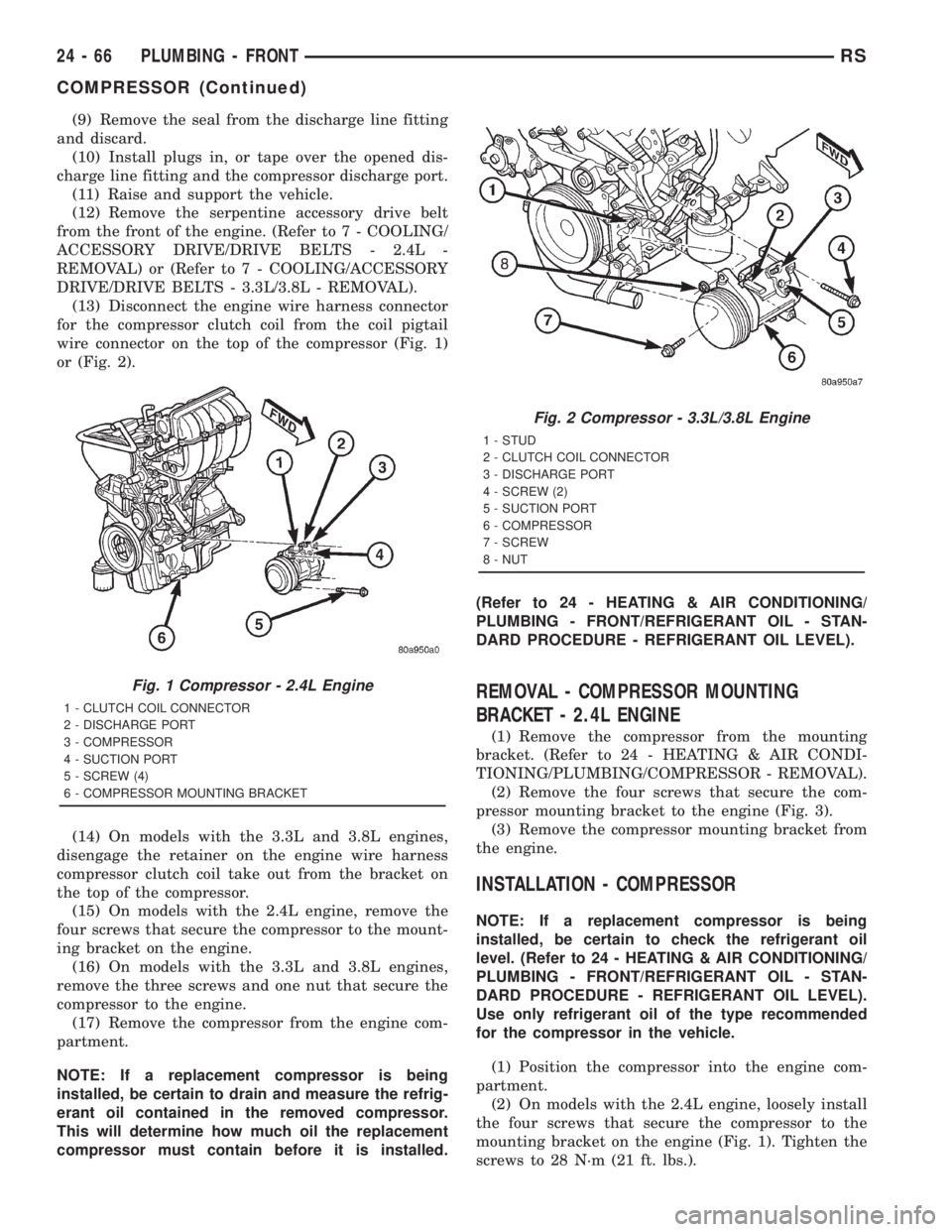
wire connector on the top of the compressor (Fig. 1)
or (Fig. 2).
(14) On models with the 3.3L and 3.8L engines,
disengage the retainer on the engine wire harness
compressor clutch coil take out from the bracket on
the top of the compressor.
(15) On models with the 2.4L engine, remove the
four screws that secure the compressor to the mount-
ing bracket on the engine.
(16) On models with the 3.3L and 3.8L engines,
remove the three screws and one nut that secure the
compressor to the engine.
(17) Remove the compressor from the engine com-
partment.
NOTE: If a replacement compressor is being
installed, be certain to drain and measure the refrig-
erant oil contained in the removed compressor.
This will determine how much oil the replacement
compressor must contain before it is installed.(Refer to 24 - HEATING & AIR CONDITIONING/
PLUMBING - FRONT/REFRIGERANT OIL - STAN-
DARD PROCEDURE - REFRIGERANT OIL LEVEL).
REMOVAL - COMPRESSOR MOUNTING
BRACKET - 2.4L ENGINE
(1) Remove the compressor from the mounting
bracket. (Refer to 24 - HEATING & AIR CONDI-
TIONING/PLUMBING/COMPRESSOR - REMOVAL).
(2) Remove the four screws that secure the com-
pressor mounting bracket to the engine (Fig. 3).
(3) Remove the compressor mounting bracket from
the engine.
INSTALLATION - COMPRESSOR
NOTE: If a replacement compressor is being
installed, be certain to check the refrigerant oil
level. (Refer to 24 - HEATING & AIR CONDITIONING/
PLUMBING - FRONT/REFRIGERANT OIL - STAN-
DARD PROCEDURE - REFRIGERANT OIL LEVEL).
Use only refrigerant oil of the type recommended
for the compressor in the vehicle.
(1) Position the compressor into the engine com-
partment.
(2) On models with the 2.4L engine, loosely install
the four screws that secure the compressor to the
mounting bracket on the engine (Fig. 1). Tighten the
screws to 28 N´m (21 ft. lbs.).
Fig. 1 Compressor - 2.4L Engine
1 - CLUTCH COIL CONNECTOR
2 - DISCHARGE PORT
3 - COMPRESSOR
4 - SUCTION PORT
5 - SCREW (4)
6 - COMPRESSOR MOUNTING BRACKET
Fig. 2 Compressor - 3.3L/3.8L Engine
1 - STUD
2 - CLUTCH COIL CONNECTOR
3 - DISCHARGE PORT
4 - SCREW (2)
5 - SUCTION PORT
6 - COMPRESSOR
7 - SCREW
8 - NUT
24 - 66 PLUMBING - FRONTRS
COMPRESSOR (Continued)
Page 3699 of 4284
INSTALLATION
NOTE: If the condenser is being replaced, add 30
milliliters (1 fluid ounce) of refrigerant oil to the
refrigerant system. Use only refrigerant oil of the
type recommended for the compressor in the vehi-
cle.
NOTE: Be certain that each of the radiator and con-
denser air seals are reinstalled in their proper loca-
tions. These air seals are required in order for the
air conditioning and engine cooling systems to per-
form as designed.
(1) Position the condenser to the right mounting
bracket and transmission oil cooler unit.
(2) Position the left mounting bracket onto the side
of the condenser and transmission oil cooler.
(3) Install and tighten the one screw that secures
the left mounting bracket to the side of the transmis-
sion oil cooler. Tighten the screw to 5 N´m (45 in.
lbs.).
(4) Install and tighten the two screws that secure
each mounting bracket to the sides of the condenser.
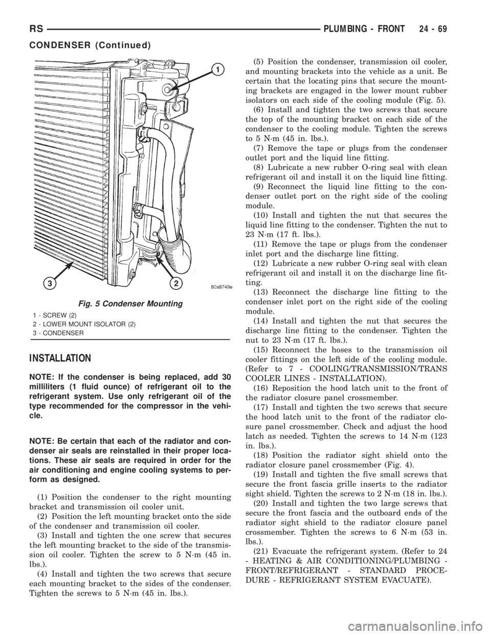
Tighten the screws to 5 N´m (45 in. lbs.).(5) Position the condenser, transmission oil cooler,
and mounting brackets into the vehicle as a unit. Be
certain that the locating pins that secure the mount-
ing brackets are engaged in the lower mount rubber
isolators on each side of the cooling module (Fig. 5).
(6) Install and tighten the two screws that secure
the top of the mounting bracket on each side of the
condenser to the cooling module. Tighten the screws
to 5 N´m (45 in. lbs.).
(7) Remove the tape or plugs from the condenser
outlet port and the liquid line fitting.
(8) Lubricate a new rubber O-ring seal with clean
refrigerant oil and install it on the liquid line fitting.
(9) Reconnect the liquid line fitting to the con-
denser outlet port on the right side of the cooling
module.
(10) Install and tighten the nut that secures the
liquid line fitting to the condenser. Tighten the nut to
23 N´m (17 ft. lbs.).
(11) Remove the tape or plugs from the condenser
inlet port and the discharge line fitting.
(12) Lubricate a new rubber O-ring seal with clean
refrigerant oil and install it on the discharge line fit-
ting.
(13) Reconnect the discharge line fitting to the
condenser inlet port on the right side of the cooling
module.
(14) Install and tighten the nut that secures the
discharge line fitting to the condenser. Tighten the
nut to 23 N´m (17 ft. lbs.).
(15) Reconnect the hoses to the transmission oil
cooler fittings on the left side of the cooling module.
(Refer to 7 - COOLING/TRANSMISSION/TRANS
COOLER LINES - INSTALLATION).
(16) Reposition the hood latch unit to the front of
the radiator closure panel crossmember.
(17) Install and tighten the two screws that secure
the hood latch unit to the front of the radiator clo-
sure panel crossmember. Check and adjust the hood
latch as needed. Tighten the screws to 14 N´m (123
in. lbs.).
(18) Position the radiator sight shield onto the
radiator closure panel crossmember (Fig. 4).
(19) Install and tighten the five small screws that
secure the front fascia grille inserts to the radiator
sight shield. Tighten the screws to 2 N´m (18 in. lbs.).
(20) Install and tighten the two large screws that
secure the front fascia and the outboard ends of the
radiator sight shield to the radiator closure panel
crossmember. Tighten the screws to 6 N´m (53 in.
lbs.).
(21) Evacuate the refrigerant system. (Refer to 24
- HEATING & AIR CONDITIONING/PLUMBING -
FRONT/REFRIGERANT - STANDARD PROCE-
DURE - REFRIGERANT SYSTEM EVACUATE).
Fig. 5 Condenser Mounting
1 - SCREW (2)
2 - LOWER MOUNT ISOLATOR (2)
3 - CONDENSER
RSPLUMBING - FRONT24-69
CONDENSER (Continued)
Page 3703 of 4284
as a unit. Be certain not to lose the clam shell type
rubber seal that is fitted to the evaporator inlet and
outlet tubes where they exit the evaporator housing.
INSTALLATION
NOTE: If the evaporator is being replaced, add 60
milliliters (2 fluid ounces) of refrigerant oil to the
refrigerant system. Use only refrigerant oil of thetype recommended for the compressor in the vehi-
cle.
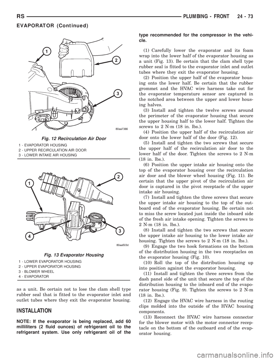
(1) Carefully lower the evaporator and its foam
wrap into the lower half of the evaporator housing as
a unit (Fig. 13). Be certain that the clam shell type
rubber seal is fitted to the evaporator inlet and outlet
tubes where they exit the evaporator housing.
(2) Position the upper half of the evaporator hous-
ing onto the lower half. Be certain that the rubber
grommet and the HVAC wire harness take out for
the evaporator temperature sensor are captured in
the notched area between the upper and lower hous-
ing halves.
(3) Install and tighten the twelve screws around
the perimeter of the evaporator housing that secure
the upper housing half to the lower half. Tighten the
screws to 2 N´m (18 in. lbs.).
(4) Position the upper half of the recirculation air
door onto the lower half of the door (Fig. 12).
(5) Install and tighten the two screws that secure
the upper half of the recirculation air door to the
lower half of the door. Tighten the screws to 2 N´m
(18 in. lbs.).
(6) Position the upper intake air housing onto the
top of the evaporator housing over the recirculation
air door and the blower wheel housing (Fig. 11). Be
certain that the upper pivot of the recirculation air
door is captured in the pivot receptacle of the upper
intake air housing.
(7) Install and tighten the three screws that secure
the upper intake air housing to the top of the out-
board end of the evaporator housing. Be certain not
to miss the screw located just inside the inboard side
of the fresh air intake opening. Tighten the screws to
2 N´m (18 in. lbs.).
(8) Install and tighten the two screws that secure
the upper intake air housing to the lower intake air
housing. Tighten the screws to 2 N´m (18 in. lbs.).
(9) Engage the two hook formations on the bottom
of the distribution housing in the two receptacles on
the evaporator housing (Fig. 10).
(10) Roll the top of the distribution housing up
into position against the evaporator housing.
(11) Install and tighten the three screws from the
dash panel side of the unit that secure the top of the
distribution housing to the inboard end of the evapo-
rator housing (Fig. 9). Tighten the screws to 2 N´m
(18 in. lbs.).
(12) Engage the HVAC wire harness in the routing
clips molded into the outside of the HVAC housing
components.
(13) Reconnect the HVAC wire harness connector
for the blower motor with the motor connector recep-
tacle on the bottom of the outboard end of the evap-
orator housing.
Fig. 12 Recirculation Air Door
1 - EVAPORATOR HOUSING
2 - UPPER RECIRCULATION AIR DOOR
3 - LOWER INTAKE AIR HOUSING
Fig. 13 Evaporator Housing
1 - LOWER EVAPORATOR HOUSING
2 - UPPER EVAPORATOR HOUSING
3 - BLOWER WHEEL
4 - EVAPORATOR
RSPLUMBING - FRONT24-73
EVAPORATOR (Continued)
Page 3716 of 4284
contaminated or left open to the atmosphere for an
indeterminable period, it must be replaced.
OPERATION
The filter-drier performs a filtering action to pre-
vent foreign material in the refrigerant from contam-
inating the expansion valve. A desiccant bag is
mounted inside the filter-drier canister to absorb any
moisture which may have entered and become
trapped within the refrigerant system. In addition,
during periods of high demand air conditioner opera-
tion, the filter-drier acts as a reservoir to store sur-
plus refrigerant. Refrigerant enters the filter-drier as
a high-pressure, low-temperature liquid.
REMOVAL
WARNING: REFER TO THE APPLICABLE WARN-
INGS AND CAUTIONS FOR THIS SYSTEM BEFORE
PERFORMING THE FOLLOWING OPERATION.
(Refer to 24 - HEATING & AIR CONDITIONING/
PLUMBING - FRONT - WARNING - A/C PLUMBING)
and (Refer to 24 - HEATING & AIR CONDITIONING/
PLUMBING - FRONT - CAUTION - A/C PLUMBING).
(1) Recover the refrigerant from the refrigerant
system. (Refer to 24 - HEATING & AIR CONDI-
TIONING/PLUMBING - FRONT/REFRIGERANT -
STANDARD PROCEDURE - REFRIGERANT
RECOVERY).
(2) Remove the air cleaner housing from the right
side of the engine compartment.
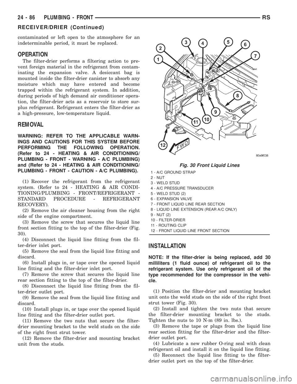
(3) Remove the screw that secures the liquid line
front section fitting to the top of the filter-drier (Fig.
30).
(4) Disconnect the liquid line fitting from the fil-
ter-drier inlet port.
(5) Remove the seal from the liquid line fitting and
discard.
(6) Install plugs in, or tape over the opened liquid
line fitting and the filter-drier inlet port.
(7) Remove the screw that secures the liquid line
rear section fitting to the top of the filter-drier.
(8) Disconnect the liquid line fitting from the fil-
ter-drier outlet port.
(9) Remove the seal from the liquid line fitting and
discard.
(10) Install plugs in, or tape over the opened liquid
line fitting and the filter-drier outlet port.
(11) Remove the two nuts that secure the filter-
drier mounting bracket to the weld studs on the side
of the right front strut tower.
(12) Remove the filter-drier and mounting bracket
unit from the studs.
INSTALLATION
NOTE: If the filter-drier is being replaced, add 30
milliliters (1 fluid ounce) of refrigerant oil to the
refrigerant system. Use only refrigerant oil of the
type recommended for the compressor in the vehi-
cle.
(1) Position the filter-drier and mounting bracket
unit onto the weld studs on the side of the right front
strut tower (Fig. 30).
(2) Install and tighten the two nuts that secure
the filter-drier mounting bracket to the studs.
Tighten the nuts to 10 N´m (89 in. lbs.).
(3) Remove the tape or plugs from the liquid line
rear section fitting for the filter-drier and the filter-
drier outlet port.
(4) Lubricate a new rubber O-ring seal with clean
refrigerant oil and install it on the liquid line fitting.
(5) Reconnect the liquid line fitting to the filter-
drier outlet port on the top of the filter-drier.
Fig. 30 Front Liquid Lines
1 - A/C GROUND STRAP
2 - NUT
3 - WELD STUD
4 - A/C PRESSURE TRANSDUCER
5 - WELD STUD (2)
6 - EXPANSION VALVE
7 - FRONT LIQUID LINE REAR SECTION
8 - LIQUID LINE EXTENSION (REAR A/C ONLY)
9 - NUT (2)
10 - FILTER-DRIER
11 - ROUTING CLIP
12 - FRONT LIQUID LINE FRONT SECTION
24 - 86 PLUMBING - FRONTRS
RECEIVER/DRIER (Continued)
Page 3719 of 4284
DIAGNOSIS AND TESTING - REFRIGERANT
SYSTEM LEAKS
WARNING: REFER TO THE APPLICABLE WARN-
INGS AND CAUTIONS FOR THIS SYSTEM BEFORE
PERFORMING THE FOLLOWING OPERATION.
(Refer to 24 - HEATING & AIR CONDITIONING/
PLUMBING - FRONT - WARNING - A/C PLUMBING)
and (Refer to 24 - HEATING & AIR CONDITIONING/
PLUMBING - FRONT - CAUTION - A/C PLUMBING).
If the air conditioning system is not cooling prop-
erly, determine if the refrigerant system is fully-
charged. (Refer to 24 - HEATING & AIR
CONDITIONING/PLUMBING - FRONT/REFRIGER-
ANT - DIAGNOSIS AND TESTING - REFRIGER-
ANT SYSTEM CHARGE LEVEL).
If the refrigerant system is low or empty; a leak at
a refrigerant line, connector fitting, component, or
component seal is likely. While an oily residue on or
near refrigerant system lines, connector fittings, com-
ponents, or component seals can indicate the general
location of a possible refrigerant leak, the exact leak
location should be confirmed with an electronic leak
detector prior to component repair or replacement.
An electronic leak detector designed for R-134a
refrigerant is recommended for locating and confirm-
ing refrigerant system leaks. See the operating
instructions supplied by the equipment manufacturer
for proper care and use of this equipment.
To detect a leak in the refrigerant system, perform
one of the following procedures as indicated by the
results of the refrigerant system charge level test.
SYSTEM EMPTY
(1) Evacuate the refrigerant system. (Refer to 24 -
HEATING & AIR CONDITIONING/PLUMBING -
FRONT/REFRIGERANT - STANDARD PROCE-
DURE - REFRIGERANT SYSTEM EVACUATE).
(2) Connect and dispense 0.283 kilograms (0.625
pounds or 10 ounces) of R-134a refrigerant into the
evacuated refrigerant system. (Refer to 24 - HEAT-
ING & AIR CONDITIONING/PLUMBING - FRONT/
REFRIGERANT - STANDARD PROCEDURE -
REFRIGERANT SYSTEM CHARGE).
(3) Proceed to the SYSTEM LOW procedures.
SYSTEM LOW
(1) Position the vehicle in a wind-free work area.
This will aid in detecting small leaks.
(2) Bring the refrigerant system up to operating
temperature and pressure. This is done by allowing
the engine to run at idle under the following condi-
tions for five minutes, then turning the engine off.
(a) Front windows are open.
(b) Rear air conditioner Off (if equipped).(c) Transaxle in Park.
(d) Front heater-A/C controls set to outside air,
panel mode, blower high, and compressor engaged.
(3) Wait five to seven minutes and, with the
engine not running, use a electronic R-134a leak
detector and search for leaks. Because R-134a refrig-
erant is heavier than air, the leak detector probe
should be moved slowly along the bottom side of all
refrigerant lines, connector fittings and components.
(4) To inspect an evaporator for leaks, insert the
electronic leak detector probe into a floor outlet or
the recirculation air intake.
STANDARD PROCEDURE - REFRIGERANT
SYSTEM SERVICE EQUIPMENT
RECOVERY/RECYCLING STATION
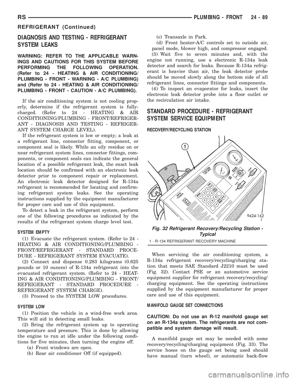
When servicing the air conditioning system, a
R-134a refrigerant recovery/recycling/charging sta-
tion that meets SAE Standard J2210 must be used
(Fig. 32). Contact PSE or an automotive service
equipment supplier for refrigerant recovery/recycling/
charging equipment. See the operating instructions
supplied by the equipment manufacturer for proper
care and use of this equipment.
MANIFOLD GAUGE SET CONNECTIONS
CAUTION: Do not use an R-12 manifold gauge set
on an R-134a system. The refrigerants are not com-
patible and system damage will result.
A manifold gauge set may be needed with some
recovery/recycling/charging equipment (Fig. 33). The
service hoses on the gauge set being used should
have manual (turn wheel), or automatic back-flow
Fig. 32 Refrigerant Recovery/Recycling Station -
Typical
1 - R-134 REFRIGERANT RECOVERY MACHINE
RSPLUMBING - FRONT24-89
REFRIGERANT (Continued)