2001 CHRYSLER VOYAGER wheel alignment
[x] Cancel search: wheel alignmentPage 2947 of 4284
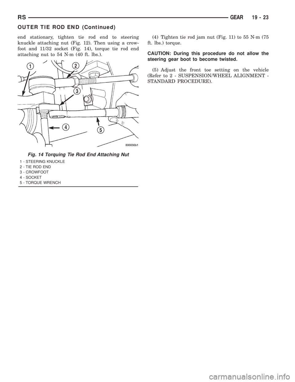
end stationary, tighten tie rod end to steering
knuckle attaching nut (Fig. 12). Then using a crow-
foot and 11/32 socket (Fig. 14), torque tie rod end
attaching nut to 54 N´m (40 ft. lbs.).(4) Tighten tie rod jam nut (Fig. 11) to 55 N´m (75
ft. lbs.) torque.
CAUTION: During this procedure do not allow the
steering gear boot to become twisted.
(5) Adjust the front toe setting on the vehicle
(Refer to 2 - SUSPENSION/WHEEL ALIGNMENT -
STANDARD PROCEDURE).
Fig. 14 Torquing Tie Rod End Attaching Nut
1 - STEERING KNUCKLE
2 - TIE ROD END
3 - CROWFOOT
4 - SOCKET
5 - TORQUE WRENCH
RSGEAR19-23
OUTER TIE ROD END (Continued)
Page 2961 of 4284
(14) If equipped, install the power steering cooler
hoses on the cooler inlet and outlet tubes. Install the
clamps.
(15) Install the front tire and wheel assemblies on
vehicle. Install the wheel mounting lug nuts and
tighten to a torque to 135 N´m (100 ft. lbs.).
(16) Lower the vehicle to a level were the interior
of vehicle is accessible (keeping tires off the ground).
(17) Using the intermediate coupler, turn the front
wheels of the vehicle to the left until the intermedi-
ate coupler shaft is properly aligned with the steer-
ing column coupler. Assemble the steering columnshaft coupler onto the steering gear intermediate
coupler (Fig. 1). Install steering column coupler to
intermediate shaft retaining pinch bolt. Tighten the
pinch bolt nut to a torque of 28 N´m (250 in. lbs.).
(18) Perform the POWER STEERING PUMP INI-
TIAL OPERATION procedure to properly fill and
bleed the power steering system. (Refer to 19 -
STEERING/PUMP - STANDARD PROCEDURE)
(19) Inspect for leaks.
(20) Adjust front wheel toe (Refer to 2 - SUSPEN-
SION/WHEEL ALIGNMENT - STANDARD PROCE-
DURE).
RGGEAR19a-5
GEAR (Continued)
Page 3375 of 4284
CLEANING - TIRES
Before delivery of a vehicle, remove the protective
coating on the tires with white sidewalls or raised
white letters. To remove the protective coating, apply
warm water and let it soak for a few minutes. After-
wards, scrub the coating away with a soft bristle
brush. Steam cleaning may also be used to remove
the coating.
CAUTION: DO NOT use gasoline, mineral oil, oil-
based solvent or a wire brush for cleaning.
WHEELS
DESCRIPTION - WHEEL
Original equipment wheels are designed for proper
operation at all loads up to the specified maximum
vehicle capacity.
All models use either steel or aluminum drop-cen-
ter wheels. Every wheel has raised sections between
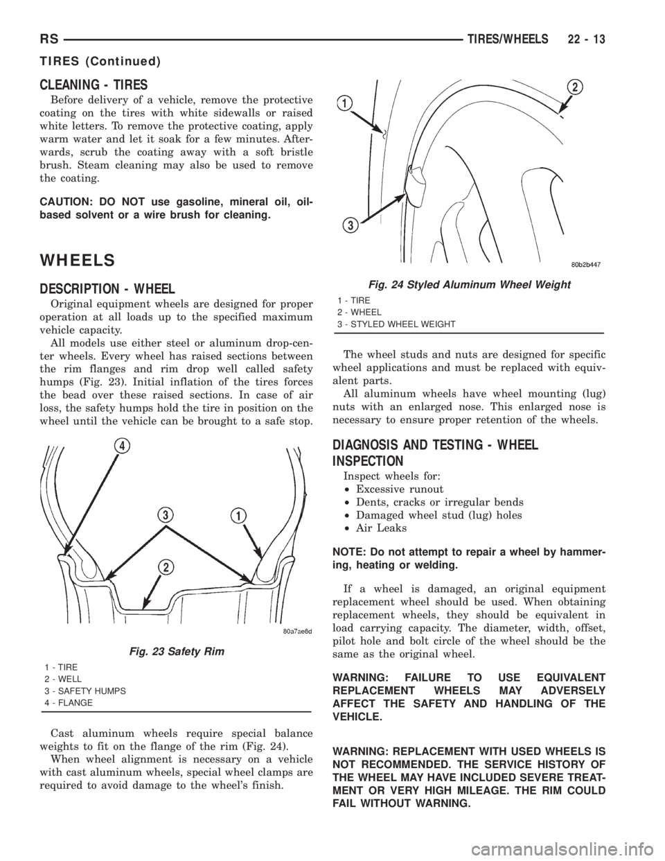
the rim flanges and rim drop well called safety
humps (Fig. 23). Initial inflation of the tires forces
the bead over these raised sections. In case of air
loss, the safety humps hold the tire in position on the
wheel until the vehicle can be brought to a safe stop.
Cast aluminum wheels require special balance
weights to fit on the flange of the rim (Fig. 24).
When wheel alignment is necessary on a vehicle
with cast aluminum wheels, special wheel clamps are
required to avoid damage to the wheel's finish.The wheel studs and nuts are designed for specific
wheel applications and must be replaced with equiv-
alent parts.
All aluminum wheels have wheel mounting (lug)
nuts with an enlarged nose. This enlarged nose is
necessary to ensure proper retention of the wheels.
DIAGNOSIS AND TESTING - WHEEL
INSPECTION
Inspect wheels for:
²Excessive runout
²Dents, cracks or irregular bends
²Damaged wheel stud (lug) holes
²Air Leaks
NOTE: Do not attempt to repair a wheel by hammer-
ing, heating or welding.
If a wheel is damaged, an original equipment
replacement wheel should be used. When obtaining
replacement wheels, they should be equivalent in
load carrying capacity. The diameter, width, offset,
pilot hole and bolt circle of the wheel should be the
same as the original wheel.
WARNING: FAILURE TO USE EQUIVALENT
REPLACEMENT WHEELS MAY ADVERSELY
AFFECT THE SAFETY AND HANDLING OF THE
VEHICLE.
WARNING: REPLACEMENT WITH USED WHEELS IS
NOT RECOMMENDED. THE SERVICE HISTORY OF
THE WHEEL MAY HAVE INCLUDED SEVERE TREAT-
MENT OR VERY HIGH MILEAGE. THE RIM COULD
FAIL WITHOUT WARNING.
Fig. 23 Safety Rim
1 - TIRE
2 - WELL
3 - SAFETY HUMPS
4 - FLANGE
Fig. 24 Styled Aluminum Wheel Weight
1 - TIRE
2 - WHEEL
3 - STYLED WHEEL WEIGHT
RSTIRES/WHEELS22-13
TIRES (Continued)
Page 3534 of 4284
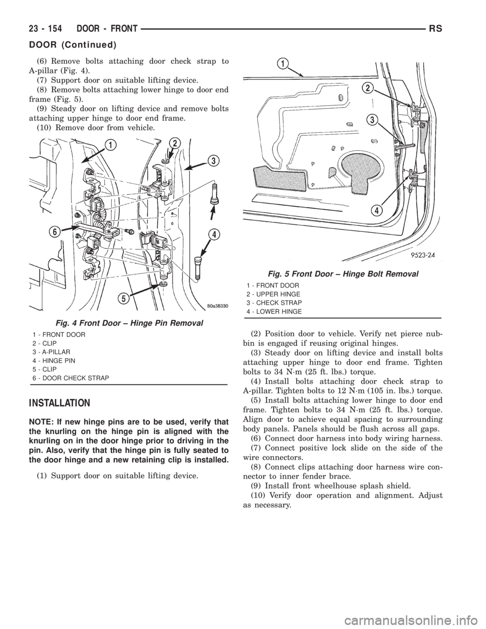
(6) Remove bolts attaching door check strap to
A-pillar (Fig. 4).
(7) Support door on suitable lifting device.
(8) Remove bolts attaching lower hinge to door end
frame (Fig. 5).
(9) Steady door on lifting device and remove bolts
attaching upper hinge to door end frame.
(10) Remove door from vehicle.
INSTALLATION
NOTE: If new hinge pins are to be used, verify that
the knurling on the hinge pin is aligned with the
knurling on in the door hinge prior to driving in the
pin. Also, verify that the hinge pin is fully seated to
the door hinge and a new retaining clip is installed.
(1) Support door on suitable lifting device.(2) Position door to vehicle. Verify net pierce nub-
bin is engaged if reusing original hinges.
(3) Steady door on lifting device and install bolts
attaching upper hinge to door end frame. Tighten
bolts to 34 N´m (25 ft. lbs.) torque.
(4) Install bolts attaching door check strap to
A-pillar. Tighten bolts to 12 N´m (105 in. lbs.) torque.
(5) Install bolts attaching lower hinge to door end
frame. Tighten bolts to 34 N´m (25 ft. lbs.) torque.
Align door to achieve equal spacing to surrounding
body panels. Panels should be flush across all gaps.
(6) Connect door harness into body wiring harness.
(7) Connect positive lock slide on the side of the
wire connectors.
(8) Connect clips attaching door harness wire con-
nector to inner fender brace.
(9) Install front wheelhouse splash shield.
(10) Verify door operation and alignment. Adjust
as necessary.
Fig. 4 Front Door ± Hinge Pin Removal
1 - FRONT DOOR
2 - CLIP
3 - A-PILLAR
4 - HINGE PIN
5 - CLIP
6 - DOOR CHECK STRAP
Fig. 5 Front Door ± Hinge Bolt Removal
1 - FRONT DOOR
2 - UPPER HINGE
3 - CHECK STRAP
4 - LOWER HINGE
23 - 154 DOOR - FRONTRS
DOOR (Continued)
Page 3574 of 4284
(5) Install fuel filler housing to outer quarter
panel.
(6) Verify that all clips on fuel filler housing are
fully engaged to outer quarter panel.
(7) Engage fuel filler lockout link into clip on fuel
fill blocker latch arm.
(8) Install water shield patch covering access hole
in C-pillar.
(9) Install left quarter trim panel.
GRILLE OPENING
REINFORCEMENT
REMOVAL
(1) Release hood latch and open hood.
(2) Remove bolts attaching hood latch to cross-
member and position latch out of the way.
(3) Remove radiator sight shield.
(4) Remove engine air inlet resonator.
(5) Remove hood cable.
(6) Remove hood prop rod.
(7) Remove screw attaching coolant recovery bottle
to crossmember.
(8) Remove bolts attaching radiator isolators to
crossmember.
(9) Remove bolts attaching ends of crossmember to
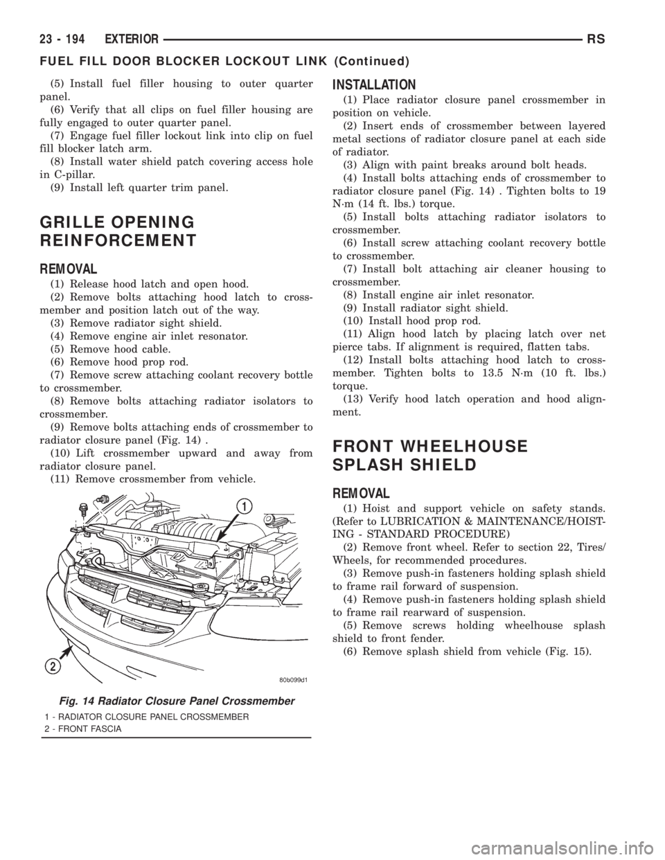
radiator closure panel (Fig. 14) .
(10) Lift crossmember upward and away from
radiator closure panel.
(11) Remove crossmember from vehicle.
INSTALLATION
(1) Place radiator closure panel crossmember in
position on vehicle.
(2) Insert ends of crossmember between layered
metal sections of radiator closure panel at each side
of radiator.
(3) Align with paint breaks around bolt heads.
(4) Install bolts attaching ends of crossmember to
radiator closure panel (Fig. 14) . Tighten bolts to 19
N´m (14 ft. lbs.) torque.
(5) Install bolts attaching radiator isolators to
crossmember.
(6) Install screw attaching coolant recovery bottle
to crossmember.
(7) Install bolt attaching air cleaner housing to
crossmember.
(8) Install engine air inlet resonator.
(9) Install radiator sight shield.
(10) Install hood prop rod.
(11) Align hood latch by placing latch over net
pierce tabs. If alignment is required, flatten tabs.
(12) Install bolts attaching hood latch to cross-
member. Tighten bolts to 13.5 N´m (10 ft. lbs.)
torque.
(13) Verify hood latch operation and hood align-
ment.
FRONT WHEELHOUSE
SPLASH SHIELD
REMOVAL
(1) Hoist and support vehicle on safety stands.
(Refer to LUBRICATION & MAINTENANCE/HOIST-
ING - STANDARD PROCEDURE)
(2) Remove front wheel. Refer to section 22, Tires/
Wheels, for recommended procedures.
(3) Remove push-in fasteners holding splash shield
to frame rail forward of suspension.
(4) Remove push-in fasteners holding splash shield
to frame rail rearward of suspension.
(5) Remove screws holding wheelhouse splash
shield to front fender.
(6) Remove splash shield from vehicle (Fig. 15).
Fig. 14 Radiator Closure Panel Crossmember
1 - RADIATOR CLOSURE PANEL CROSSMEMBER
2 - FRONT FASCIA
23 - 194 EXTERIORRS
FUEL FILL DOOR BLOCKER LOCKOUT LINK (Continued)
Page 4119 of 4284
then notice harsh bumps when the A/C clutch is
being cycled, but vehicle shudder will be elimi-
nated. After 35 OBDII (EURO STAGE III OBD)
warm-up starts or if the code is cleared, PEMCC
will be reactivated to see if shudder is still present.
If one shudder event occurs, the code will be reset.
Clearing the code and running battery disconnect
with the DRBIIItis the only way to reset the
shudder counter from 20 back to zero.
Transmission Effects:This code does not cause
the transmission to go into limp-in mode. However,
once the code is set, FEMCC to PEMCC operation
before the A/C clutch engagement will be disabled
for 35 OBDII (EURO STAGE III OBD) warm up
starts.
Possible causes:
> Degraded transmission fluid
> Wheels severely out of alignment
> Internal torque converter problem
Name of Code:P1799(74) - Calculated Oil Temper-
ature in Use
When Monitored:When ever the Engine is run-
ning.
Set condition:The code is set if any of the follow-
ing conditions exist for three consecutive key starts:
> The Temperature Sensor voltage is out of range
(below 0.07 volts or greater than 4.94 volts)
> If continuous erratic Temperature Sensor voltage
is sensed.
> The Temperature Sensor temperature stays be-
low 27C (80ÉF) for an extended period of time.
Theory of Operation:The TCM uses a Tempera-
ture Sensor to monitor the transmission sump tem-
perature. This temperature is used to determine
which shift schedule the TCM is to use. (See Trans-
mission Operation and Shift Scheduling at Various
Sump Temperatures in this diagnostic manual) If
the Temperature Sensor circuit fails to operate
properly the TCM will use the calculated oil tem-
perature routine found in prior model year TCM. If
this occurs for three consecutive key starts, the code
will be set. The TCM will then test the Temperature
Sensor circuit after every 35 OBDII (EURO STAGE
III OBD) warm-up starts. If the Temperature Sen-
sor circuit is OK, the Temperature Sensor data is
used in place of the Calculated Oil Temperature
data.
Transmission Effects:If the Temperature Sensor
indicates a temperature below -18C (0É F) or above
115C (240É F) at start up, The TCM compares the
calculated oil temperature to the indicated Temper-
ature Sensor oil temperature. If the calculated oil
temperature differs significantly from the Temper-
ature Sensor value, the calculated oil temperature
will be used for that key start.Possible Causes:
> Wiring or Connector problems in the transmis-
sion temperature sensor signal circuit.
> TRS
> TCM
Name of Code:P1738(75) - High Temperature
Operation Activated.
When Monitored:Whenever the engine is running.
Set Condition:Immediately once the Overheat
Shift Schedule is activated.
Theory of Operation:If the transmission oil tem-
perature rises above 115C (240ÉF), the overheat
shift schedule is activated refer to Transmission
Operation as a function of Transmission Oil Tem-
perature and the code is set. The DTC is an infor-
mation code only and is being set to aid the techni-
cian in determining root cause of a customer
driveability issue. The code is also intended to alert
the technician to determine if a cooling system
malfunction has occurred or if an additional trans-
mission air to oil cooler should be added to the
vehicle if the customer regularly drives in a manner
that overheats the transmission. Extended opera-
tion above 115C (240ÉF) will reduce the durability of
the transmission and should be avoided. Correcting
the cooling system malfunction or installing an
additional transmission oil cooler will improve
transmission durability especially for customers
who operate in city/construction stop and go traffic,
tow trailers regularly, drive aggressively in low gear
or drive regularly in mountainous areas.
Transmission Effects:Information only code. -
Overheat shift schedule was activated, no limp-in
condition occurs. 2nd gear partial EMCC above 40
Km/h (25 MPH), 3rd gear EMCC from 45-69 Km/h
(28-43 MPH), delayed 3-4 upshift at 69 Km/h (43
MPH), early 4-3 coastdown at 66 Km/h (41 MPH),
EMCC operation under all conditions above 40
Km/h (25 MPH) except at closed throttle or 1st gear.
Possible Causes:
± Transmission Overfilled with Oil
± Engine cooling fan failure
± Engine thermostat stuck closed
± Radiator corroded or packed with dirt
± Transmission Oil Cooler Plugged
± Customer driving pattern requires additional
transmission cooling
Name Of Code:P1739(76) - Power-Up at Speed
When Monitored:When TCM (transmission con-
trol module) initially powers-up.
Set Condition:If the TCM powers up while in the
9Drive9position and the vehicle is going above 32
Km/h (20 MPH), the code is set.
Theory of Operation:If a vehicle loses power to
the TCM, the vehicle will go to the 2nd gear mode
15
GENERAL INFORMATION