2001 CHRYSLER VOYAGER ECO mode
[x] Cancel search: ECO modePage 1158 of 4284
1.0 INTRODUCTION
The procedures contained in this manual include
all the specifications, instructions, and graphics
needed to diagnose Mark 20 Antilock Braking Sys-
tem (ABS) and Mark 20 Antilock Braking System
with Traction Control. The diagnostics in this man-
ual are based on the failure condition or symptom
being present at time of diagnosis.
Please follow the recommendations below when
choosing your diagnostic path.
1. First make sure the DRBIIItis communicating
with the CAB. If the DRBIIItdisplays a ªNo
Responseº condition, you must diagnose that
first.
2. Read DTC's (diagnostic trouble codes) with the
DRBIIIt.
3. If no DTC's are present, identify the customer
complaint.
4. Once the DTC or customer complaint is identi-
fied, locate the matching test in the Table of
Contents and begin to diagnose the symptom.
All component location views are in Section 8.0.
All connector pinouts are in Section 9.0. All sche-
matics are in Section 10.0.
An * placed before the symptom description indi-
cates a concern with no associated DTC.
When repairs are required, refer to the appropri-
ate service manual for the proper removal and
repair procedure.
Diagnostic procedures change every year. New
diagnostic systems may be added; carry over sys-
tems may be enhanced. READ THIS MANUAL
BEFORE TRYING TO DIAGNOSE A VEHICLE
CODE. It is recommended that you review the
entire manual to become familiar with all new and
changed diagnostic procedures.
After using this book, if you have any comments
or recommendations, please fill out the form at the
back of the book and mail it back to us.
1.1 SYSTEM COVERAGE
This diagnostic procedure manual covers the an-
tilock braking system (ABS) and traction control
system found on: 2001 Chrysler Town and Country,
Dodge Caravan and Grand Caravan.
1.2 SIX-STEP TROUBLESHOOTING
PROCEDURE
Diagnosis of the controller antilock brake module
is done in six basic steps:
²verification of complaint
²verification of any related symptoms
²symptom analysis
²problem isolation
²repair of isolated problem
²verification of proper operation
2.0 IDENTIFICATION OF
SYSTEM
Vehicles equipped with the Teves Mark 20 an-
tilock brake system can be identified by the pres-
ence of the controller antilock brake module located
beneath the master cylinder.
3.0 SYSTEM DESCRIPTION AND
FUNCTIONAL OPERATION
3.1 TEVES MARK 20 SYSTEM
DESCRIPTION
The controller antilock brake module is used to
monitor wheel speeds and to modulate (control)
hydraulic pressure in each brake channel. The
modulated hydraulic pressure is used to prevent
wheel lock-up during braking.
The Teves Mark 20 system uses a diagonal split
hydraulic brake system.
In the standard brake mode
the master cylinder primary circuit supplies pressure
to the right front and left rear wheel brakes, and the
secondary master cylinder circuit supplies pressure
to the left front and right rear wheel brakes.
3.2 TRACTION CONTROL SYSTEM (TCS)
DESCRIPTION
The main purpose of traction control is to reduce
wheel slip and maintain traction at the driven
wheels when road surfaces are slippery. The trac-
tion control system reduces wheel slip by braking
the wheel that is losing traction. The system is
designed to operate at speeds below 56 km/h (35
mph).
The Controller Antilock Brake (CAB) monitors
wheel speeds. If, during acceleration, the module
detects front (drive) wheel slip and the brakes are
not applied, the CAB will enter traction control
mode. Traction control works in the following order
when drive wheel slip is detected.
1. Close the (normally open) isolation valves.
2. Start pump/motor and supply volume/pressure
to front hydraulic circuits (pump runs continu-
ously during traction control).
3. Open and close build and decay valves to main-
tain minimum wheel slip and maximum trac-
tion.
1
GENERAL INFORMATION
Page 1159 of 4284
The cycling of the build and decay valves is
similar to the ABS except that they work to control
wheel spin by applying brakes. ABS function is to
control wheel skid by releasing brakes.
Two pressure relief valves allow excess fluid vol-
ume to return to the reservoir when not used by the
build/decay cycles. These are required because the
pump supplies more volume than the traction con-
trol system requires.
If at any time the brake pedal is applied during a
traction control cycle, the brake lamp switch will
trigger the CAB to switch off the traction control.
The traction control system will be enabled at
each ignition cycle. It may be turned off by depress-
ing the Traction Control Switch. The traction con-
trol system function lamp will illuminate ªTRAC
OFFº immediately upon depressing the traction
control switch button. Only the ªTRACº portion of
the ªTRAC OFFº indicator will illuminate during a
traction control event. If the CAB calculates that
the brake temperatures are high, the traction con-
trol system will become inoperative until a time-out
period has elapsed. When in this thermal protection
mode, the traction control ªTRAC OFFº lamp will
illuminate; however, a fault will not be registered.
3.3 SYSTEM COMPONENTS
²controller antilock brake (CAB)
²vacuum booster
²master cylinder
²ABS integrated electronic control module/
hydraulic control unit (HCU), valve block assem-
bly: 8 valve solenoids (4 inlet valves, 4 outlet
valves, 2 accumulators) 1 motor, 2 pump
²ABS integrated electronic control module with
traction control same as above but has 10 valve
solenoids.
²4 wheel speed sensor/tone wheel assemblies
²ABS warning indicator
²fuses and wiring harness
²fluid reservoir
²TRAC/TRAC OFF indicator
3.3.1 ABS AND BRAKE WARNING
INDICATORS
The amber ABS warning indicator is located in
the instrument cluster. It is used to inform the
driver that the antilock function has been turned
off. The ABS warning indicator is controlled by the
CAB. The CAB controls the lamp with a command
over the PCI bus.
The ABS Warning Indicator will remain lit during
every key cycle until a circuit or component fault is
repaired and the CAB no longer detects the fault.After repair of a sensor signal fault or a pump motor
fault, the CAB must sense all four wheels at 25
km/h (15 mph) before it will extinguish the ABS and
TRAC OFF Indicators.
The Instrument Cluster will illuminate the ABS
Warning Indicator if it loses communication with
the CAB.
The red BRAKE warning indicator is also located
in the instrument cluster. It can be activated in
several ways. Application of the parking brake or a
low fluid signal from the fluid level switch located in
the master cylinder reservoir will cause the indica-
tor to come on.
3.3.2 CONTROLLER ANTILOCK BRAKE
(CAB)
The Controller Antilock Brake (CAB) is a
microprocessor-based device that monitors wheel
speeds and controls the antilock functions. The
CAB contains two microprocessors that receive
identical sensor signals and then independently
process the information. The results are then com-
pared to make sure that they agree. Otherwise, the
CAB will turn off the antilock and turn on the ABS
amber warning indicator.
The primary functions of the CAB are to:
²detect wheel locking tendencies
²control fluid pressure modulation to the brakes
during antilock stop
²monitor the system for proper operation
²manage traction control functions
²provide communication to the DRBIIItwhile in
diagnostic mode
²store diagnostic information in non-volatile memory
The CAB continuously monitors the speed of each
wheel. When a wheel locking tendency is detected,
the CAB will command the appropriate valve to
modulate brake fluid pressure in its hydraulic unit.
Brake pedal position is maintained during an an-
tilock stop by being a closed system with the use of
2 accumulators. The CAB continues to control pres-
sure in individual hydraulic circuits until a wheel
locking tendency is no longer present. The CAB
turns on the pump motor during an antilock stop.
The antilock brake system is constantly moni-
tored by the CAB for proper operation. If the CAB
detects a system malfunction, it can disable the
antilock system and turn on the ABS warning
indicator. If the antilock function is disabled, the
system will revert to standard base brake system
operation.
The CAB inputs include the following:
²diagnostic communication
²four wheel speed sensors
2
GENERAL INFORMATION
Page 1161 of 4284
the brake pedal is applied the test will be run at 40
km/h (24 mph) regardless of brake switch state. If,
during the dynamic test, the brake pedal is applied,
the driver may feel the test through brake pedal
pulsations. This is a normal condition.
If any component exhibits a trouble condition
during system initialization or dynamic check, the
CAB will illuminate the ABS warning indicator and
TRAC OFF lamp if equipped.
3.3.6 DIAGNOSTIC MODE
To enter diagnostic mode, a vehicle speed must be
below 10 km/h (6 mph) and no ABS condition
present. If vehicle speed is not below 10 km/h
(6 mph), a ªNo Responseº message could be dis-
played by the DRBIIIt. The following are charac-
teristics of diagnostic mode:
± The amber ABS warning indicator will blink
rapidly (about 1/2 second ON and 1/2 second
OFF). If a hard trouble code, such as Valve
Power Feed Failure code is present, the indi-
cator will be illuminated without blinking un-
til the trouble condition is cleared.
± Antilock operation is disabled.
± The HCU valves cannot be actuated when the
vehicle speed is above 8 km/h (5 mph). If valve
actuation is attempted above 8 km/h (5 mph), a
ªNo Responseº message will be displayed on
the DRBIIIt.
3.4 DIAGNOSTIC TROUBLE CODES
The controller antilock brake may report any of
the following diagnostic trouble codes:
CLUSTER LAMP FAILURE
VALVE POWER FEED FAILURE
BUS SYSTEM COMMUNICATION FAILURE
CAB INTERNAL FAILURE
LEFT FRONT SENSOR CIRCUIT FAILURE
LEFT FRONT WHEEL SPEED SIGNAL
FAILURE
LEFT REAR SENSOR CIRCUIT FAILURE
LEFT REAR WHEEL SPEED SIGNAL
FAILURE
PUMP CIRCUIT FAILURE
RIGHT FRONT SENSOR CIRCUIT FAILURE
RIGHT FRONT WHEEL SPEED SIGNAL
FAILURE
RIGHT REAR SENSOR CIRCUIT FAILURE
RIGHT REAR WHEEL SPEED SIGNAL
FAILURE
SYSTEM OVERVOLTAGE
SYSTEM UNDERVOLTAGE
3.5 DRBIIITERROR MESSAGES AND
BLANK SCREEN
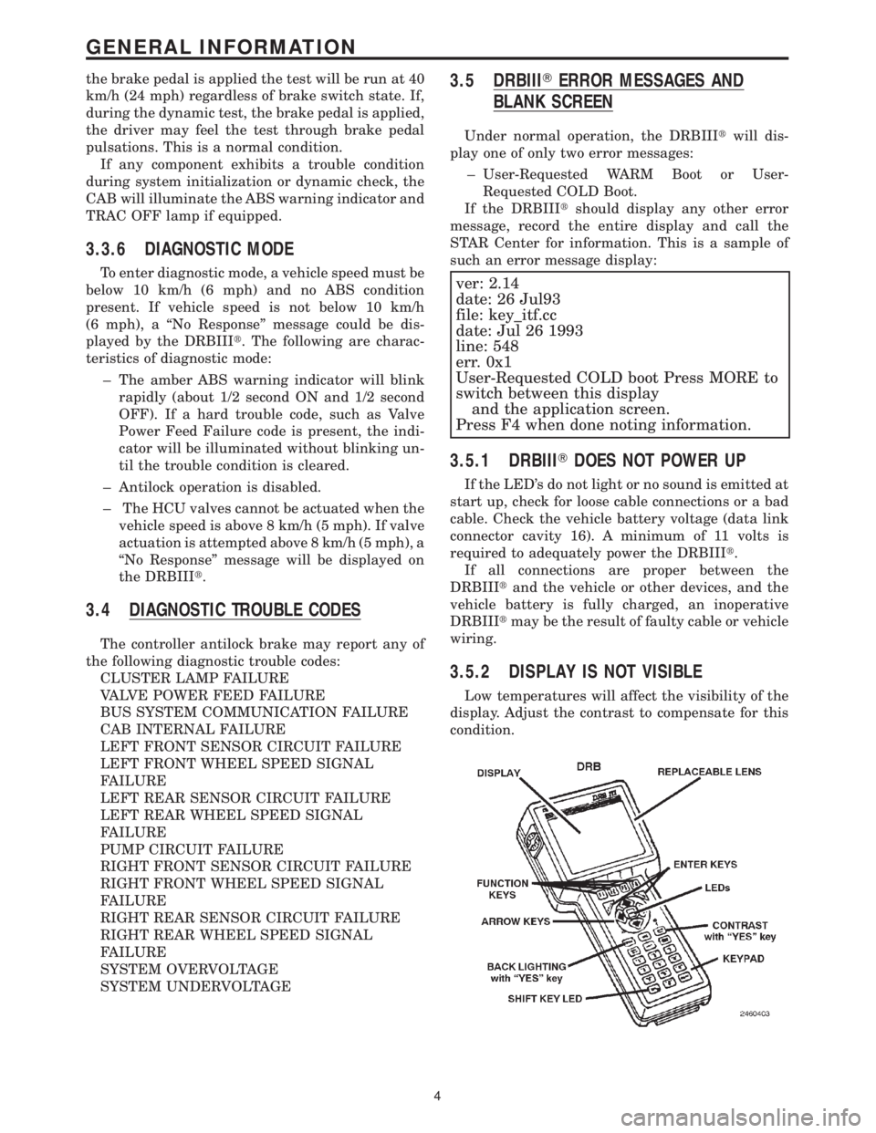
Under normal operation, the DRBIIItwill dis-
play one of only two error messages:
± User-Requested WARM Boot or User-
Requested COLD Boot.
If the DRBIIItshould display any other error
message, record the entire display and call the
STAR Center for information. This is a sample of
such an error message display:
ver: 2.14
date: 26 Jul93
file: key_itf.cc
date: Jul 26 1993
line: 548
err. 0x1
User-Requested COLD boot Press MORE to
switch between this display
and the application screen.
Press F4 when done noting information.
3.5.1 DRBIIITDOES NOT POWER UP
If the LED's do not light or no sound is emitted at
start up, check for loose cable connections or a bad
cable. Check the vehicle battery voltage (data link
connector cavity 16). A minimum of 11 volts is
required to adequately power the DRBIIIt.
If all connections are proper between the
DRBIIItand the vehicle or other devices, and the
vehicle battery is fully charged, an inoperative
DRBIIItmay be the result of faulty cable or vehicle
wiring.
3.5.2 DISPLAY IS NOT VISIBLE
Low temperatures will affect the visibility of the
display. Adjust the contrast to compensate for this
condition.
4
GENERAL INFORMATION
Page 1221 of 4284
3.2.2 ECM OPERATING MODES
As input signals to the ECM change, the ECM
adjusts its response to the output devices. For
example, the ECM must calculate a different fuel
quantity and fuel timing for engine idle condition
than it would for a wide open throttle condition.
There are several different modes of operation that
determine how the ECM responds to the various
input signals.
Ignition Switch On (Engine Off)
When the ignition switch is turned on, the ECM
activates the glow plug relay for a time period that
is determined by engine coolant temperature, atmo-
spheric temperature and battery voltage. The ECM
also activates the lift pump to prime the fuel sys-
tem.
Engine Start-up Mode
The ECM uses the engine temperature sensor
and the crankshaft position sensor (engine speed)
inputs to determine fuel injection quantity.
Normal Driving Modes
Engine idle, warm-up, acceleration, deceleration
and wide open throttle modes are controlled based
on all of the sensor inputs to the ECM. The ECM
uses these sensor inputs to adjust fuel quantity and
fuel injector timing.
Overheat Protection Mode
If engine temperature is above 106É C (223É F)
and vehicle speed is above 40 km/h (25 MPH) the
ECM will activate the high speed fan and will limit
fuel quantity for engine protection.
Limp-In Mode
If there is a fault detected with the accelerator
pedal position sensor, the ECM will set the engine
speed at 1100 RPM.
Overspeed Detection Mode
If the ECM detects engine RPM that exceeds
5000 RPM, the ECM will set a DTC in memory and
limit engine RPM to no more that 2500 RPM until
the DTC(s) is cleared.
After-Run Mode
The ECM transfers RAM information to ROM
and performs an Input/Output state check.
3.2.3 MONITORED CIRCUITS
The ECM is able to monitor and identify most
driveability related trouble conditions. Some cir-
cuits are directly monitored through ECM feedback
circuitry. In addition, the ECM monitors the voltage
state of some circuits and compares those stateswith expected values. Other systems are monitored
indirectly when the ECM conducts a rationality test
to identify problems.
Although most subsystems of the engine control
module are either directly or indirectly monitored,
there may be occasions when diagnostic trouble
codes are not immediately identified. For a trouble
code to set, a specific set of conditions must occur
and unless these conditions occur, a DTC will not
set.
3.2.4 SKIS OVERIVEW
The sentry key immobilizer system (SKIS) is
designed to prevent unauthorized vehicle opera-
tion. The system consists of a sentry key immobi-
lizer module (SKIM), ignition key(s) equipped with
a transponder chip and the ECM. When the ignition
switch is turned on, the SKIM interrogates the
ignition key. If the ignition key is Valid or Invalid,
the SKIM sends a PCI Bus message to the ECM
indicating ignition key status. Upon receiving this
message the ECM will terminate engine operation
or allow the engine to continue to operate.
3.2.5 SKIS ON-BOARD DIAGNOSTICS
The sentry key immobilizer module (SKIM) has
been programmed to transmit and monitor many
different coded messages as well as PCI Bus mes-
sages. This monitoring is called On-Board Diagnos-
tics. Certain criteria must be met for a DTC to be
entered into SKIM memory. The criteria may be a
range of; input voltage, PCI Bus message or coded
messages to the SKIM. If all of the criteria for
monitoring a circuit or function are met and a fault
is detected, a DTC will be stored in the SKIM
memory.
3.2.6 SKIS OPERATION
When ignition power is supplied to the SKIM, the
SKIM performs an internal self-test. After the self-
test is complete, the SKIM energizes the antenna
(this activates the transponder chip) and sends a
challenge to the transponder chip. The transponder
chip responds to the challenge by generating an
encrypted response message using the following:
Secret Key - This is an electronically stored value
(identification number) that is unique to each SKIS.
The secret key is stored in the SKIM, ECM and all
ignition key transponders.
Challenge - This is a random number that is gen-
erated by the SKIM at each ignition key cycle.
The secret key and challenge are the two vari-
ables used in the algorithm that produces the
encrypted response message. The transponder uses
the crypto algorithm to receive, decode and respond
to the message sent by SKIM. After responding to
the coded message, the transponder sends a tran-
2
GENERAL INFORMATION
Page 1222 of 4284
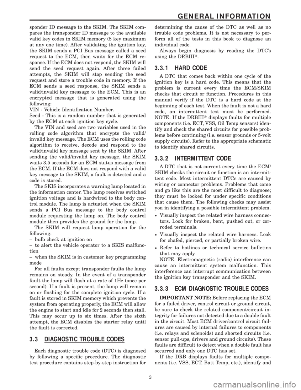
sponder ID message to the SKIM. The SKIM com-
pares the transponder ID message to the available
valid key codes in SKIM memory (8 key maximum
at any one time). After validating the ignition key,
the SKIM sends a PCI Bus message called a seed
request to the ECM, then waits for the ECM re-
sponse. If the ECM does not respond, the SKIM will
send the seed request again. After three failed
attempts, the SKIM will stop sending the seed
request and store a trouble code in memory. If the
ECM sends a seed response, the SKIM sends a
valid/invalid key message to the ECM. This is an
encrypted message that is generated using the
following:
VIN - Vehicle Identification Number.
Seed - This is a random number that is generated
by the ECM at each ignition key cycle.
The VIN and seed are two variables used in the
rolling code algorithm that encrypts the valid/
invalid key message. The ECM uses the rolling code
algorithm to receive, decode and respond to the
valid/invalid key message sent by the SKIM. After
sending the valid/invalid key message, the SKIM
waits 3.5 seconds for an ECM status message from
the ECM. If the ECM does not respond with a valid
key message to the SKIM, a fault is detected and a
code is stored.
The SKIS incorporates a warning lamp located in
the information center. The lamp receives switched
ignition voltage and is hardwired to the body con-
trol module. The lamp is actuated when the SKIM
sends a PCI Bus message to the body control
module requesting the lamp on. The body control
module then provides the ground for the lamp.
The SKIM will request lamp operation for the
following:
± bulb check at ignition on
± to alert the vehicle operator to a SKIS malfunc-
tion
± when the SKIM is in customer key programming
mode
For all faults except transponder faults the lamp
remains on steady. In the event of a transponder
fault the lamp will flash at a rate of 1Hz (once per
second). If a fault is present, the lamp will remain
on or flashing for the complete ignition cycle. If a
fault is stored in SKIM memory which prevents the
system from operating properly, the ECM will allow
the engine to start and idle for 2 seconds then stall.
This may occur up to six times. After the sixth
attempt, the ECM disables the starter relay until
the fault is corrected.
3.3 DIAGNOSTIC TROUBLE CODES
Each diagnostic trouble code (DTC) is diagnosed
by following a specific procedure. The diagnostic
test procedure contains step-by-step instruction fordetermining the cause of the DTC as well as no
trouble code problems. It is not necessary to per-
form all of the tests in this book to diagnose an
individual code.
Always begin diagnosis by reading the DTC's
using the DRBIIIt.
3.3.1 HARD CODE
A DTC that comes back within one cycle of the
ignition key is a hard code. This means that the
problem is current every time the ECM/SKIM
checks that circuit or function. Procedures in this
manual verify if the DTC is a hard code at the
beginning of each test. When the fault is not a hard
code, an intermittent test must be performed.
NOTE: If the DRBIIItdisplays faults for multiple
components (i.e. ECT, VSS, Oil Temp sensors) iden-
tify and check the shared circuits for possible prob-
lems before continuing (i.e. sensor grounds or 5-volt
supply circuits). Refer to the appropriate schematic
to identify shared circuits.
3.3.2 INTERMITTENT CODE
A DTC that is not current every time the ECM/
SKIM checks the circuit or function is an intermit-
tent code. Most intermittent DTCs are caused by
wiring or connector problems. Problems that come
and go like this are the most difficult to diagnose;
they must be looked for under specific conditions
that cause them. The following checks may assist
you in identifying a possible intermittent problem.
²Visually inspect the related wire harness connec-
tors. Look for broken, bent, pushed out, or cor-
roded terminals.
²Visually inspect the related wire harness. Look
for chafed, pierced, or partially broken wire.
²Refer to hotlines or technical service bulletins
that may apply.
NOTE: Electromagnetic (radio) interference can
cause an intermittent system malfunction. This
interference can interrupt communication between
the ignition key transponder and the SKIM.
3.3.3 ECM DIAGNOSTIC TROUBLE CODES
IMPORTANT NOTE:Before replacing the ECM
for a failed driver, control circuit or ground circuit,
be sure to check the related component/circuit in-
tegrity for failures not detected due to a double fault
in the circuit. Most ECM driver/control circuit fail-
ures are caused by internal failures to components
(i.e. relays and solenoids) and shorted circuits (i.e.
sensor pull-ups, drivers and ground circuits). These
faults are difficult to detect when a double fault has
occurred and only one DTC has set.
If the DRB displays faults for multiple compo-
nents (i.e. VSS, ECT, Batt Temp, etc.), identify and
3
GENERAL INFORMATION
Page 1364 of 4284
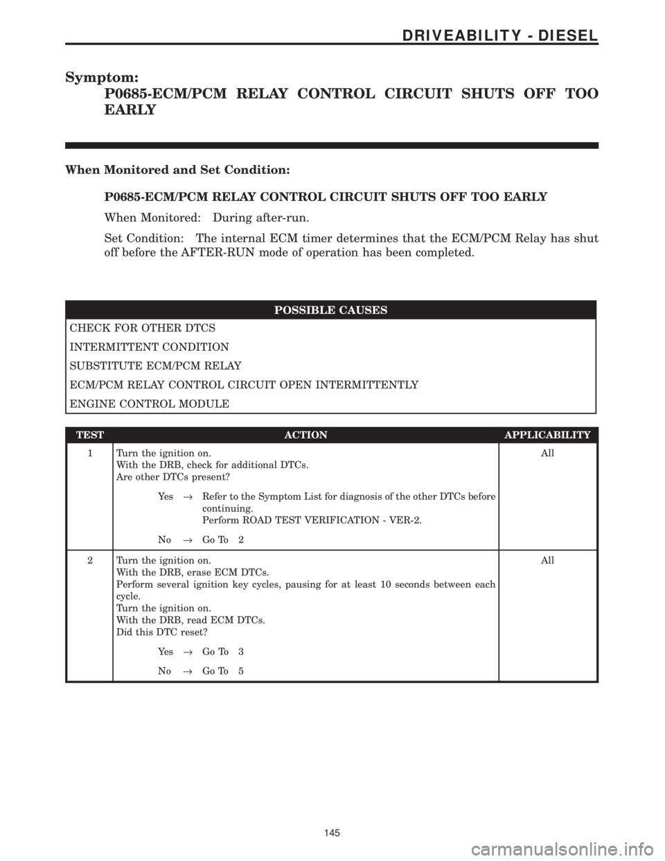
Symptom:
P0685-ECM/PCM RELAY CONTROL CIRCUIT SHUTS OFF TOO
EARLY
When Monitored and Set Condition:
P0685-ECM/PCM RELAY CONTROL CIRCUIT SHUTS OFF TOO EARLY
When Monitored: During after-run.
Set Condition: The internal ECM timer determines that the ECM/PCM Relay has shut
off before the AFTER-RUN mode of operation has been completed.
POSSIBLE CAUSES
CHECK FOR OTHER DTCS
INTERMITTENT CONDITION
SUBSTITUTE ECM/PCM RELAY
ECM/PCM RELAY CONTROL CIRCUIT OPEN INTERMITTENTLY
ENGINE CONTROL MODULE
TEST ACTION APPLICABILITY
1 Turn the ignition on.
With the DRB, check for additional DTCs.
Are other DTCs present?All
Ye s®Refer to the Symptom List for diagnosis of the other DTCs before
continuing.
Perform ROAD TEST VERIFICATION - VER-2.
No®Go To 2
2 Turn the ignition on.
With the DRB, erase ECM DTCs.
Perform several ignition key cycles, pausing for at least 10 seconds between each
cycle.
Turn the ignition on.
With the DRB, read ECM DTCs.
Did this DTC reset?All
Ye s®Go To 3
No®Go To 5
145
DRIVEABILITY - DIESEL
Page 1366 of 4284
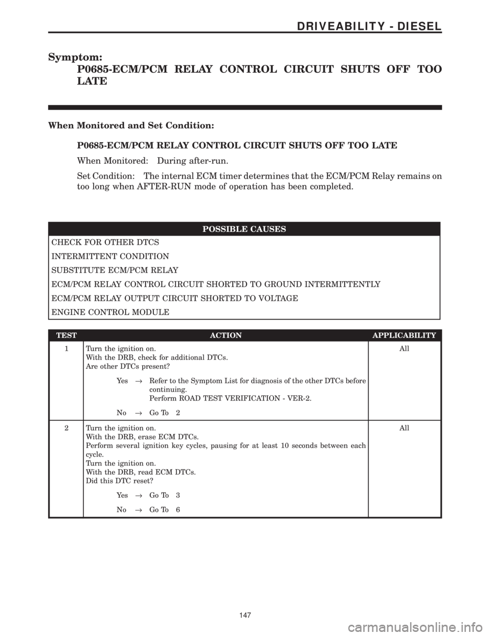
Symptom:
P0685-ECM/PCM RELAY CONTROL CIRCUIT SHUTS OFF TOO
LATE
When Monitored and Set Condition:
P0685-ECM/PCM RELAY CONTROL CIRCUIT SHUTS OFF TOO LATE
When Monitored: During after-run.
Set Condition: The internal ECM timer determines that the ECM/PCM Relay remains on
too long when AFTER-RUN mode of operation has been completed.
POSSIBLE CAUSES
CHECK FOR OTHER DTCS
INTERMITTENT CONDITION
SUBSTITUTE ECM/PCM RELAY
ECM/PCM RELAY CONTROL CIRCUIT SHORTED TO GROUND INTERMITTENTLY
ECM/PCM RELAY OUTPUT CIRCUIT SHORTED TO VOLTAGE
ENGINE CONTROL MODULE
TEST ACTION APPLICABILITY
1 Turn the ignition on.
With the DRB, check for additional DTCs.
Are other DTCs present?All
Ye s®Refer to the Symptom List for diagnosis of the other DTCs before
continuing.
Perform ROAD TEST VERIFICATION - VER-2.
No®Go To 2
2 Turn the ignition on.
With the DRB, erase ECM DTCs.
Perform several ignition key cycles, pausing for at least 10 seconds between each
cycle.
Turn the ignition on.
With the DRB, read ECM DTCs.
Did this DTC reset?All
Ye s®Go To 3
No®Go To 6
147
DRIVEABILITY - DIESEL
Page 1439 of 4284
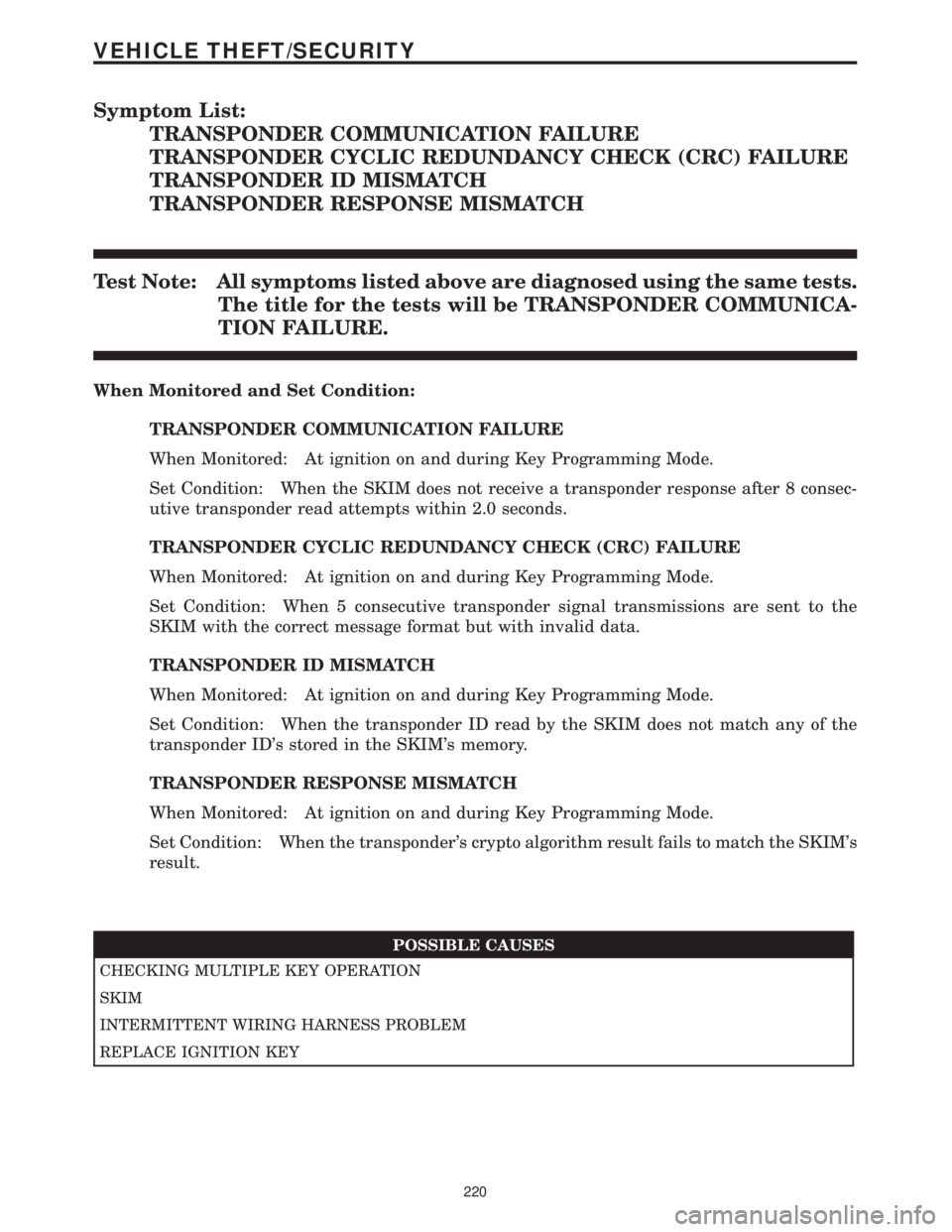
Symptom List:
TRANSPONDER COMMUNICATION FAILURE
TRANSPONDER CYCLIC REDUNDANCY CHECK (CRC) FAILURE
TRANSPONDER ID MISMATCH
TRANSPONDER RESPONSE MISMATCH
Test Note: All symptoms listed above are diagnosed using the same tests.
The title for the tests will be TRANSPONDER COMMUNICA-
TION FAILURE.
When Monitored and Set Condition:
TRANSPONDER COMMUNICATION FAILURE
When Monitored: At ignition on and during Key Programming Mode.
Set Condition: When the SKIM does not receive a transponder response after 8 consec-
utive transponder read attempts within 2.0 seconds.
TRANSPONDER CYCLIC REDUNDANCY CHECK (CRC) FAILURE
When Monitored: At ignition on and during Key Programming Mode.
Set Condition: When 5 consecutive transponder signal transmissions are sent to the
SKIM with the correct message format but with invalid data.
TRANSPONDER ID MISMATCH
When Monitored: At ignition on and during Key Programming Mode.
Set Condition: When the transponder ID read by the SKIM does not match any of the
transponder ID's stored in the SKIM's memory.
TRANSPONDER RESPONSE MISMATCH
When Monitored: At ignition on and during Key Programming Mode.
Set Condition: When the transponder's crypto algorithm result fails to match the SKIM's
result.
POSSIBLE CAUSES
CHECKING MULTIPLE KEY OPERATION
SKIM
INTERMITTENT WIRING HARNESS PROBLEM
REPLACE IGNITION KEY
220
VEHICLE THEFT/SECURITY