2001 CHRYSLER VOYAGER oil pressure
[x] Cancel search: oil pressurePage 1353 of 4284
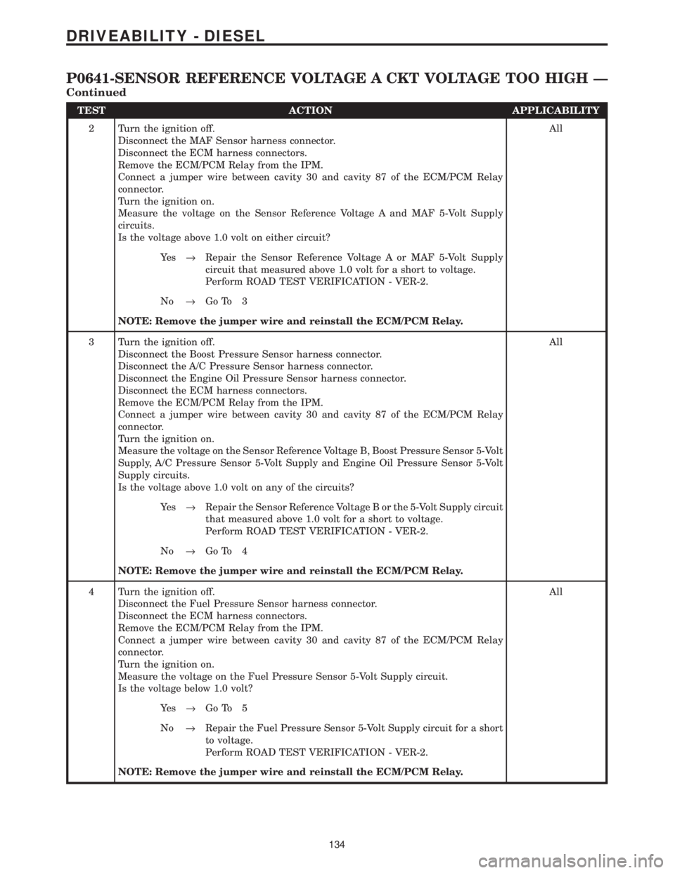
TEST ACTION APPLICABILITY
2 Turn the ignition off.
Disconnect the MAF Sensor harness connector.
Disconnect the ECM harness connectors.
Remove the ECM/PCM Relay from the IPM.
Connect a jumper wire between cavity 30 and cavity 87 of the ECM/PCM Relay
connector.
Turn the ignition on.
Measure the voltage on the Sensor Reference Voltage A and MAF 5-Volt Supply
circuits.
Is the voltage above 1.0 volt on either circuit?All
Ye s®Repair the Sensor Reference Voltage A or MAF 5-Volt Supply
circuit that measured above 1.0 volt for a short to voltage.
Perform ROAD TEST VERIFICATION - VER-2.
No®Go To 3
NOTE: Remove the jumper wire and reinstall the ECM/PCM Relay.
3 Turn the ignition off.
Disconnect the Boost Pressure Sensor harness connector.
Disconnect the A/C Pressure Sensor harness connector.
Disconnect the Engine Oil Pressure Sensor harness connector.
Disconnect the ECM harness connectors.
Remove the ECM/PCM Relay from the IPM.
Connect a jumper wire between cavity 30 and cavity 87 of the ECM/PCM Relay
connector.
Turn the ignition on.
Measure the voltage on the Sensor Reference Voltage B, Boost Pressure Sensor 5-Volt
Supply, A/C Pressure Sensor 5-Volt Supply and Engine Oil Pressure Sensor 5-Volt
Supply circuits.
Is the voltage above 1.0 volt on any of the circuits?All
Ye s®Repair the Sensor Reference Voltage B or the 5-Volt Supply circuit
that measured above 1.0 volt for a short to voltage.
Perform ROAD TEST VERIFICATION - VER-2.
No®Go To 4
NOTE: Remove the jumper wire and reinstall the ECM/PCM Relay.
4 Turn the ignition off.
Disconnect the Fuel Pressure Sensor harness connector.
Disconnect the ECM harness connectors.
Remove the ECM/PCM Relay from the IPM.
Connect a jumper wire between cavity 30 and cavity 87 of the ECM/PCM Relay
connector.
Turn the ignition on.
Measure the voltage on the Fuel Pressure Sensor 5-Volt Supply circuit.
Is the voltage below 1.0 volt?All
Ye s®Go To 5
No®Repair the Fuel Pressure Sensor 5-Volt Supply circuit for a short
to voltage.
Perform ROAD TEST VERIFICATION - VER-2.
NOTE: Remove the jumper wire and reinstall the ECM/PCM Relay.
134
DRIVEABILITY - DIESEL
P0641-SENSOR REFERENCE VOLTAGE A CKT VOLTAGE TOO HIGH Ð
Continued
Page 1356 of 4284
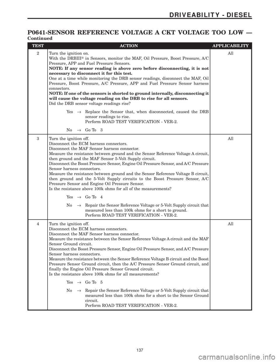
TEST ACTION APPLICABILITY
2 Turn the ignition on.
With the DRBIIItin Sensors, monitor the MAF, Oil Pressure, Boost Pressure, A/C
Pressure, APP and Fuel Pressure Sensors.
NOTE: If any sensor reading is above zero before disconnecting, it is not
necessary to disconnect it for this test.
One at a time while monitoring the DRB sensor readings, disconnect the MAF, Oil
Pressure, Boost Pressure, A/C Pressure, APP and Fuel Pressure Sensor harness
connectors.
NOTE: If one of the sensors is shorted to ground internally, disconnecting it
will cause the voltage reading on the DRB to rise for all sensors.
Did the DRB sensor voltage readings rise?All
Ye s®Replace the Sensor that, when disconnected, caused the DRB
sensor readings to rise.
Perform ROAD TEST VERIFICATION - VER-2.
No®Go To 3
3 Turn the ignition off.
Disconnect the ECM harness connectors.
Disconnect the MAF Sensor harness connector.
Measure the resistance between ground and the Sensor Reference Voltage A circuit,
then ground and the MAF Sensor 5-Volt Supply circuit.
Disconnect the Boost Pressure Sensor, Engine Oil Pressure Sensor, and A/C Pressure
Sensor harness connectors.
Measure the resistance between ground and the Sensor Reference Voltage B circuit,
then ground and the 5-Volt Supply circuits to the Boost Pressure Sensor, A/C
Pressure Sensor and Engine Oil Pressure Sensor.
Is the resistance above 100k ohms for all of the measurements?All
Ye s®Go To 4
No®Repair the Sensor Reference Voltage or 5-Volt Supply circuit that
measured less than 100k ohms for a short to ground.
Perform ROAD TEST VERIFICATION - VER-2.
4 Turn the ignition off.
Disconnect the ECM harness connectors.
Disconnect the MAF Sensor harness connector.
Measure the resistance between the Sensor Reference Voltage A circuit and the MAF
Sensor Ground circuit.
Disconnect the Boost Pressure Sensor, Engine Oil Pressure Sensor, and A/C Pressure
Sensor harness connectors.
Measure the resistance between the Sensor Reference Voltage B circuit and the Boost
Pressure Sensor Ground circuit, then the A/C Pressure Sensor Ground circuit, and
finally the Engine Oil Pressure Sensor Ground circuit.
Is the resistance above 100k ohms for all measurements?All
Ye s®Go To 5
No®Repair the Sensor Reference Voltage or 5-Volt Supply circuit that
measured less than 100k ohms for a short to the Sensor Ground
circuit.
Perform ROAD TEST VERIFICATION - VER-2.
137
DRIVEABILITY - DIESEL
P0641-SENSOR REFERENCE VOLTAGE A CKT VOLTAGE TOO LOW Ð
Continued
Page 1453 of 4284
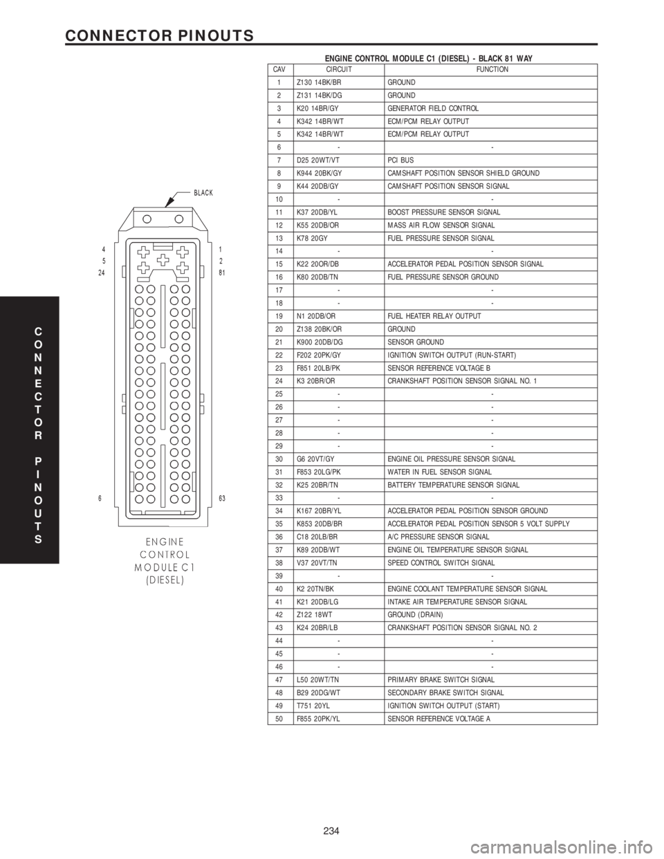
ENGINE CONTROL MODULE C1 (DIESEL) - BLACK 81 WAYCAV CIRCUIT FUNCTION
1 Z130 14BK/BR GROUND
2 Z131 14BK/DG GROUND
3 K20 14BR/GY GENERATOR FIELD CONTROL
4 K342 14BR/WT ECM/PCM RELAY OUTPUT
5 K342 14BR/WT ECM/PCM RELAY OUTPUT
6- -
7 D25 20WT/VT PCI BUS
8 K944 20BK/GY CAMSHAFT POSITION SENSOR SHIELD GROUND
9 K44 20DB/GY CAMSHAFT POSITION SENSOR SIGNAL
10 - -
11 K37 20DB/YL BOOST PRESSURE SENSOR SIGNAL
12 K55 20DB/OR MASS AIR FLOW SENSOR SIGNAL
13 K78 20GY FUEL PRESSURE SENSOR SIGNAL
14 - -
15 K22 20OR/DB ACCELERATOR PEDAL POSITION SENSOR SIGNAL
16 K80 20DB/TN FUEL PRESSURE SENSOR GROUND
17 - -
18 - -
19 N1 20DB/OR FUEL HEATER RELAY OUTPUT
20 Z138 20BK/OR GROUND
21 K900 20DB/DG SENSOR GROUND
22 F202 20PK/GY IGNITION SWITCH OUTPUT (RUN-START)
23 F851 20LB/PK SENSOR REFERENCE VOLTAGE B
24 K3 20BR/OR CRANKSHAFT POSITION SENSOR SIGNAL NO. 1
25 - -
26 - -
27 - -
28 - -
29 - -
30 G6 20VT/GY ENGINE OIL PRESSURE SENSOR SIGNAL
31 F853 20LG/PK WATER IN FUEL SENSOR SIGNAL
32 K25 20BR/TN BATTERY TEMPERATURE SENSOR SIGNAL
33 - -
34 K167 20BR/YL ACCELERATOR PEDAL POSITION SENSOR GROUND
35 K853 20DB/BR ACCELERATOR PEDAL POSITION SENSOR 5 VOLT SUPPLY
36 C18 20LB/BR A/C PRESSURE SENSOR SIGNAL
37 K89 20DB/WT ENGINE OIL TEMPERATURE SENSOR SIGNAL
38 V37 20VT/TN SPEED CONTROL SWITCH SIGNAL
39 - -
40 K2 20TN/BK ENGINE COOLANT TEMPERATURE SENSOR SIGNAL
41 K21 20DB/LG INTAKE AIR TEMPERATURE SENSOR SIGNAL
42 Z122 18WT GROUND (DRAIN)
43 K24 20BR/LB CRANKSHAFT POSITION SENSOR SIGNAL NO. 2
44 - -
45 - -
46 - -
47 L50 20WT/TN PRIMARY BRAKE SWITCH SIGNAL
48 B29 20DG/WT SECONDARY BRAKE SWITCH SIGNAL
49 T751 20YL IGNITION SWITCH OUTPUT (START)
50 F855 20PK/YL SENSOR REFERENCE VOLTAGE A
C
O
N
N
E
C
T
O
R
P
I
N
O
U
T
S
234
CONNECTOR PINOUTS
Page 1454 of 4284
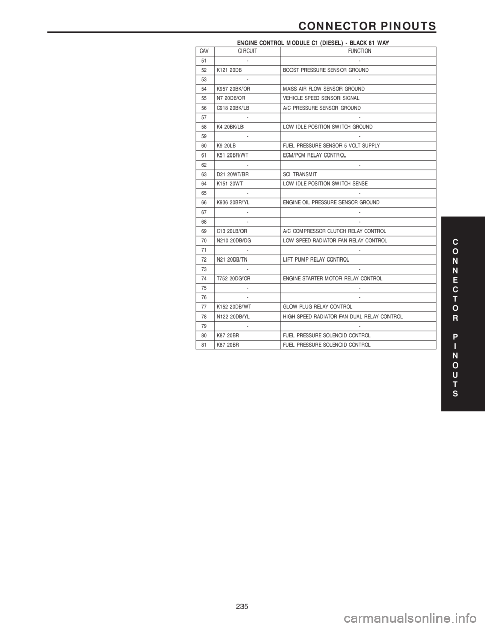
ENGINE CONTROL MODULE C1 (DIESEL) - BLACK 81 WAYCAV CIRCUIT FUNCTION
51 - -
52 K121 20DB BOOST PRESSURE SENSOR GROUND
53 - -
54 K957 20BK/OR MASS AIR FLOW SENSOR GROUND
55 N7 20DB/OR VEHICLE SPEED SENSOR SIGNAL
56 C918 20BK/LB A/C PRESSURE SENSOR GROUND
57 - -
58 K4 20BK/LB LOW IDLE POSITION SWITCH GROUND
59 - -
60 K9 20LB FUEL PRESSURE SENSOR 5 VOLT SUPPLY
61 K51 20BR/WT ECM/PCM RELAY CONTROL
62 - -
63 D21 20WT/BR SCI TRANSMIT
64 K151 20WT LOW IDLE POSITION SWITCH SENSE
65 - -
66 K936 20BR/YL ENGINE OIL PRESSURE SENSOR GROUND
67 - -
68 - -
69 C13 20LB/OR A/C COMPRESSOR CLUTCH RELAY CONTROL
70 N210 20DB/DG LOW SPEED RADIATOR FAN RELAY CONTROL
71 - -
72 N21 20DB/TN LIFT PUMP RELAY CONTROL
73 - -
74 T752 20DG/OR ENGINE STARTER MOTOR RELAY CONTROL
75 - -
76 - -
77 K152 20DB/WT GLOW PLUG RELAY CONTROL
78 N122 20DB/YL HIGH SPEED RADIATOR FAN DUAL RELAY CONTROL
79 - -
80 K87 20BR FUEL PRESSURE SOLENOID CONTROL
81 K87 20BR FUEL PRESSURE SOLENOID CONTROL
C
O
N
N
E
C
T
O
R
P
I
N
O
U
T
S
235
CONNECTOR PINOUTS
Page 1456 of 4284
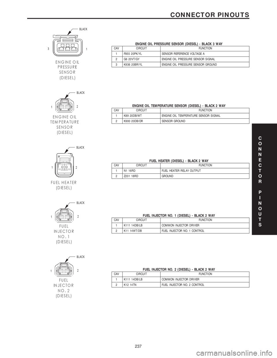
ENGINE OIL PRESSURE SENSOR (DIESEL) - BLACK 3 WAYCAV CIRCUIT FUNCTION
1 F855 20PK/YL SENSOR REFERENCE VOLTAGE A
2 G6 20VT/GY ENGINE OIL PRESSURE SENSOR SIGNAL
3 K936 20BR/YL ENGINE OIL PRESSURE SENSOR GROUND
ENGINE OIL TEMPERATURE SENSOR (DIESEL) - BLACK 2 WAYCAV CIRCUIT FUNCTION
1 K89 20DB/WT ENGINE OIL TEMPERATURE SENSOR SIGNAL
2 K900 20DB/OR SENSOR GROUND
FUEL HEATER (DIESEL) - BLACK 2 WAYCAV CIRCUIT FUNCTION
1 N1 16RD FUEL HEATER RELAY OUTPUT
2 Z201 18RD GROUND
FUEL INJECTOR NO. 1 (DIESEL) - BLACK 2 WAYCAV CIRCUIT FUNCTION
1 K111 14DB/LB COMMON INJECTOR DRIVER
2 K11 14WT/DB FUEL INJECTOR NO. 1 CONTROL
FUEL INJECTOR NO. 2 (DIESEL) - BLACK 2 WAYCAV CIRCUIT FUNCTION
1 K111 14DB/LB COMMON INJECTOR DRIVER
2 K12 14TN FUEL INJECTOR NO. 2 CONTROL
C
O
N
N
E
C
T
O
R
P
I
N
O
U
T
S
237
CONNECTOR PINOUTS
Page 1494 of 4284
NOTE: Intentional tampering with emissions control
systems can result in civil penalties being assessed
against you.
GEAR LUBRICATION ± RATINGS
SAE ratings also apply to multiple grade gear
lubricants. In addition, API classification defines the
lubricants usage.
DESCRIPTION - ENGINE COOLANT
WARNING: ANTIFREEZE IS AN ETHYLENE GLYCOL
BASE COOLANT AND IS HARMFUL IF SWAL-
LOWED OR INHALED. IF SWALLOWED, DRINK
TWO GLASSES OF WATER AND INDUCE VOMIT-
ING. IF INHALED, MOVE TO FRESH AIR AREA.
SEEK MEDICAL ATTENTION IMMEDIATELY. DO NOT
STORE IN OPEN OR UNMARKED CONTAINERS.
WASH SKIN AND CLOTHING THOROUGHLY AFTER
COMING IN CONTACT WITH ETHYLENE GLYCOL.
KEEP OUT OF REACH OF CHILDREN. DISPOSE OF
GLYCOL BASE COOLANT PROPERLY, CONTACT
YOUR DEALER OR GOVERNMENT AGENCY FOR
LOCATION OF COLLECTION CENTER IN YOUR
AREA. DO NOT OPEN A COOLING SYSTEM WHEN
THE ENGINE IS AT OPERATING TEMPERATURE OR
HOT UNDER PRESSURE, PERSONAL INJURY CAN
RESULT. AVOID RADIATOR COOLING FAN WHEN
ENGINE COMPARTMENT RELATED SERVICE IS
PERFORMED, PERSONAL INJURY CAN RESULT.
CAUTION: Use of Propylene Glycol based coolants
is not recommended, as they provide less freeze
protection and less corrosion protection.
The cooling system is designed around the coolant.
The coolant must accept heat from engine metal, in
the cylinder head area near the exhaust valves and
engine block. Then coolant carries the heat to the
radiator where the tube/fin radiator can transfer the
heat to the air.
The use of aluminum cylinder blocks, cylinder
heads, and water pumps requires special corrosion
protection. MopartAntifreeze/Coolant, 5 Year/
100,000 Mile Formula (MS-9769), or the equivalent
ethylene glycol base coolant with organic corrosion
inhibitors (called HOAT, for Hybrid Organic Additive
Technology) is recommended. This coolant offers the
best engine cooling without corrosion when mixed
with 50% Ethylene Glycol and 50% distilled water to
obtain a freeze point of -37ÉC (-35ÉF). If it loses color
or becomes contaminated, drain, flush, and replace
with fresh properly mixed coolant solution.CAUTION: MoparTAntifreeze/Coolant, 5 Year/
100,000 Mile Formula (MS-9769) may not be mixed
with any other type of antifreeze. Doing so will
reduce the corrosion protection and may result in
premature water pump seal failure. If non-HOAT
coolant is introduced into the cooling system in an
emergency, it should be replaced with the specified
coolant as soon as possible.
DESCRIPTION - LUBRICANTS AND GREASES
When service is required, DaimlerChrysler Corpo-
ration recommends that only Mopartbrand parts,
lubricants and chemicals be used. Mopartprovides
the best engineered products for servicing
DaimlerChrysler Corporation vehicles.
Only lubricants bearing designations defined by
the following organization should be used to service a
Chrysler Corporation vehicle.
²Society of Automotive Engineers (SAE)
²American Petroleum Institute (API) (Fig. 6)
²National Lubricating Grease Institute (NLGI)
(Fig. 7)
SAE VISCOSITY RATING
An SAE viscosity grade is used to specify the vis-
cosity of engine oil. These are specified with a dual
SAE viscosity grade which indicates the cold-to-hot
temperature viscosity range. Example SAE 5W-30 =
multiple grade engine oil.
DaimlerChrysler Corporation only recommends
multiple grade engine oils.
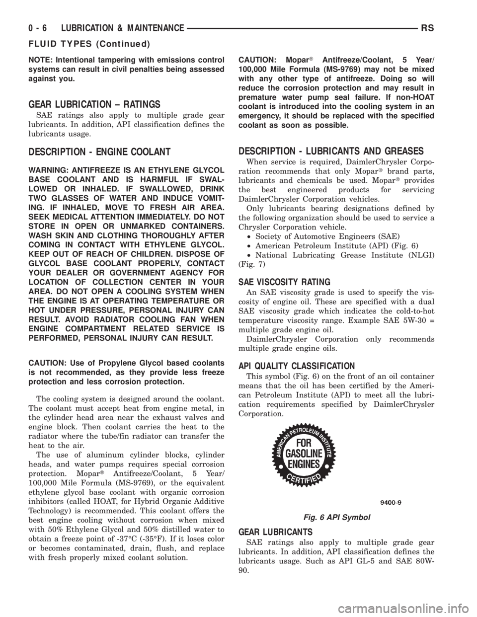
API QUALITY CLASSIFICATION
This symbol (Fig. 6) on the front of an oil container
means that the oil has been certified by the Ameri-
can Petroleum Institute (API) to meet all the lubri-
cation requirements specified by DaimlerChrysler
Corporation.
GEAR LUBRICANTS
SAE ratings also apply to multiple grade gear
lubricants. In addition, API classification defines the
lubricants usage. Such as API GL-5 and SAE 80W-
90.
Fig. 6 API Symbol
0 - 6 LUBRICATION & MAINTENANCERS
FLUID TYPES (Continued)
Page 1495 of 4284
LUBRICANTS AND GREASES
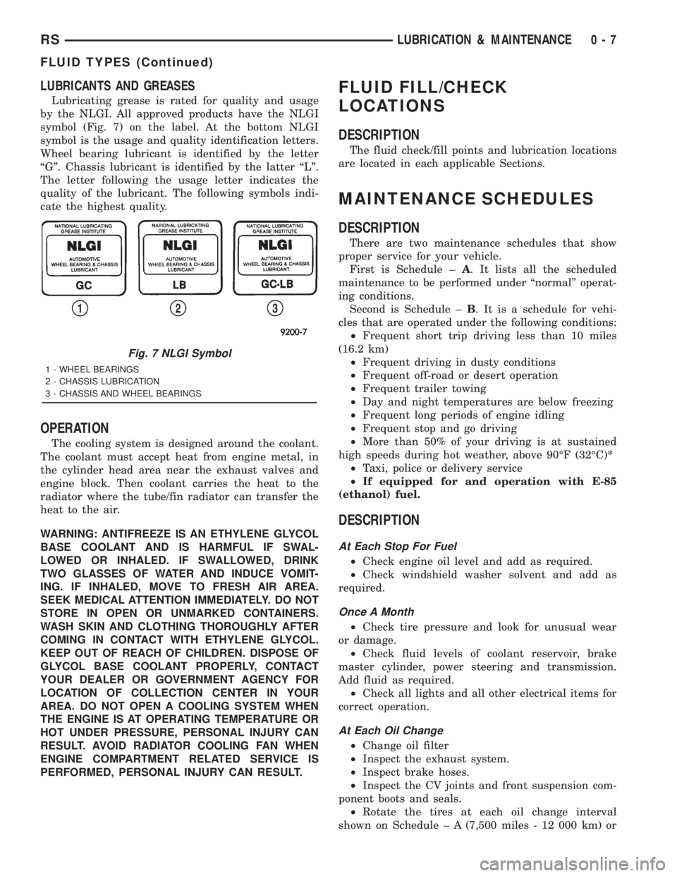
Lubricating grease is rated for quality and usage
by the NLGI. All approved products have the NLGI
symbol (Fig. 7) on the label. At the bottom NLGI
symbol is the usage and quality identification letters.
Wheel bearing lubricant is identified by the letter
ªGº. Chassis lubricant is identified by the latter ªLº.
The letter following the usage letter indicates the
quality of the lubricant. The following symbols indi-
cate the highest quality.
OPERATION
The cooling system is designed around the coolant.
The coolant must accept heat from engine metal, in
the cylinder head area near the exhaust valves and
engine block. Then coolant carries the heat to the
radiator where the tube/fin radiator can transfer the
heat to the air.
WARNING: ANTIFREEZE IS AN ETHYLENE GLYCOL
BASE COOLANT AND IS HARMFUL IF SWAL-
LOWED OR INHALED. IF SWALLOWED, DRINK
TWO GLASSES OF WATER AND INDUCE VOMIT-
ING. IF INHALED, MOVE TO FRESH AIR AREA.
SEEK MEDICAL ATTENTION IMMEDIATELY. DO NOT
STORE IN OPEN OR UNMARKED CONTAINERS.
WASH SKIN AND CLOTHING THOROUGHLY AFTER
COMING IN CONTACT WITH ETHYLENE GLYCOL.
KEEP OUT OF REACH OF CHILDREN. DISPOSE OF
GLYCOL BASE COOLANT PROPERLY, CONTACT
YOUR DEALER OR GOVERNMENT AGENCY FOR
LOCATION OF COLLECTION CENTER IN YOUR
AREA. DO NOT OPEN A COOLING SYSTEM WHEN
THE ENGINE IS AT OPERATING TEMPERATURE OR
HOT UNDER PRESSURE, PERSONAL INJURY CAN
RESULT. AVOID RADIATOR COOLING FAN WHEN
ENGINE COMPARTMENT RELATED SERVICE IS
PERFORMED, PERSONAL INJURY CAN RESULT.
FLUID FILL/CHECK
LOCATIONS
DESCRIPTION
The fluid check/fill points and lubrication locations
are located in each applicable Sections.
MAINTENANCE SCHEDULES
DESCRIPTION
There are two maintenance schedules that show
proper service for your vehicle.
First is Schedule ±A. It lists all the scheduled
maintenance to be performed under ªnormalº operat-
ing conditions.
Second is Schedule ±B. It is a schedule for vehi-
cles that are operated under the following conditions:
²Frequent short trip driving less than 10 miles
(16.2 km)
²Frequent driving in dusty conditions
²Frequent off-road or desert operation
²Frequent trailer towing
²Day and night temperatures are below freezing
²Frequent long periods of engine idling
²Frequent stop and go driving
²More than 50% of your driving is at sustained
high speeds during hot weather, above 90ÉF (32ÉC)*
²Taxi, police or delivery service
²If equipped for and operation with E-85
(ethanol) fuel.
DESCRIPTION
At Each Stop For Fuel
²Check engine oil level and add as required.
²Check windshield washer solvent and add as
required.
Once A Month
²Check tire pressure and look for unusual wear
or damage.
²Check fluid levels of coolant reservoir, brake
master cylinder, power steering and transmission.
Add fluid as required.
²Check all lights and all other electrical items for
correct operation.
At Each Oil Change
²Change oil filter
²Inspect the exhaust system.
²Inspect brake hoses.
²Inspect the CV joints and front suspension com-
ponent boots and seals.
²Rotate the tires at each oil change interval
shown on Schedule ± A (7,500 miles - 12 000 km) or
Fig. 7 NLGI Symbol
1 - WHEEL BEARINGS
2 - CHASSIS LUBRICATION
3 - CHASSIS AND WHEEL BEARINGS
RSLUBRICATION & MAINTENANCE0-7
FLUID TYPES (Continued)
Page 1509 of 4284
LUBRICANTS AND GREASES
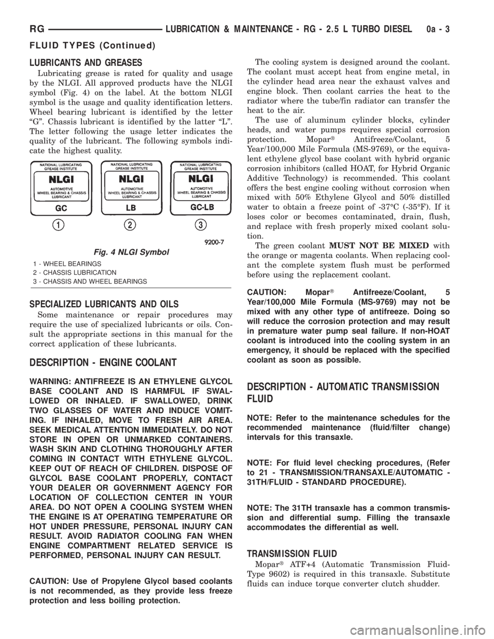
Lubricating grease is rated for quality and usage
by the NLGI. All approved products have the NLGI
symbol (Fig. 4) on the label. At the bottom NLGI
symbol is the usage and quality identification letters.
Wheel bearing lubricant is identified by the letter
ªGº. Chassis lubricant is identified by the latter ªLº.
The letter following the usage letter indicates the
quality of the lubricant. The following symbols indi-
cate the highest quality.
SPECIALIZED LUBRICANTS AND OILS
Some maintenance or repair procedures may
require the use of specialized lubricants or oils. Con-
sult the appropriate sections in this manual for the
correct application of these lubricants.
DESCRIPTION - ENGINE COOLANT
WARNING: ANTIFREEZE IS AN ETHYLENE GLYCOL
BASE COOLANT AND IS HARMFUL IF SWAL-
LOWED OR INHALED. IF SWALLOWED, DRINK
TWO GLASSES OF WATER AND INDUCE VOMIT-
ING. IF INHALED, MOVE TO FRESH AIR AREA.
SEEK MEDICAL ATTENTION IMMEDIATELY. DO NOT
STORE IN OPEN OR UNMARKED CONTAINERS.
WASH SKIN AND CLOTHING THOROUGHLY AFTER
COMING IN CONTACT WITH ETHYLENE GLYCOL.
KEEP OUT OF REACH OF CHILDREN. DISPOSE OF
GLYCOL BASE COOLANT PROPERLY, CONTACT
YOUR DEALER OR GOVERNMENT AGENCY FOR
LOCATION OF COLLECTION CENTER IN YOUR
AREA. DO NOT OPEN A COOLING SYSTEM WHEN
THE ENGINE IS AT OPERATING TEMPERATURE OR
HOT UNDER PRESSURE, PERSONAL INJURY CAN
RESULT. AVOID RADIATOR COOLING FAN WHEN
ENGINE COMPARTMENT RELATED SERVICE IS
PERFORMED, PERSONAL INJURY CAN RESULT.
CAUTION: Use of Propylene Glycol based coolants
is not recommended, as they provide less freeze
protection and less boiling protection.The cooling system is designed around the coolant.
The coolant must accept heat from engine metal, in
the cylinder head area near the exhaust valves and
engine block. Then coolant carries the heat to the
radiator where the tube/fin radiator can transfer the
heat to the air.
The use of aluminum cylinder blocks, cylinder
heads, and water pumps requires special corrosion
protection. MopartAntifreeze/Coolant, 5
Year/100,000 Mile Formula (MS-9769), or the equiva-
lent ethylene glycol base coolant with hybrid organic
corrosion inhibitors (called HOAT, for Hybrid Organic
Additive Technology) is recommended. This coolant
offers the best engine cooling without corrosion when
mixed with 50% Ethylene Glycol and 50% distilled
water to obtain a freeze point of -37ÉC (-35ÉF). If it
loses color or becomes contaminated, drain, flush,
and replace with fresh properly mixed coolant solu-
tion.
The green coolantMUST NOT BE MIXEDwith
the orange or magenta coolants. When replacing cool-
ant the complete system flush must be performed
before using the replacement coolant.
CAUTION: MoparTAntifreeze/Coolant, 5
Year/100,000 Mile Formula (MS-9769) may not be
mixed with any other type of antifreeze. Doing so
will reduce the corrosion protection and may result
in premature water pump seal failure. If non-HOAT
coolant is introduced into the cooling system in an
emergency, it should be replaced with the specified
coolant as soon as possible.DESCRIPTION - AUTOMATIC TRANSMISSION
FLUID
NOTE: Refer to the maintenance schedules for the
recommended maintenance (fluid/filter change)
intervals for this transaxle.
NOTE: For fluid level checking procedures, (Refer
to 21 - TRANSMISSION/TRANSAXLE/AUTOMATIC -
31TH/FLUID - STANDARD PROCEDURE).
NOTE: The 31TH transaxle has a common transmis-
sion and differential sump. Filling the transaxle
accommodates the differential as well.
TRANSMISSION FLUID
MopartATF+4 (Automatic Transmission Fluid-
Type 9602) is required in this transaxle. Substitute
fluids can induce torque converter clutch shudder.
Fig. 4 NLGI Symbol
1 - WHEEL BEARINGS
2 - CHASSIS LUBRICATION
3 - CHASSIS AND WHEEL BEARINGS
RGLUBRICATION & MAINTENANCE - RG - 2.5 L TURBO DIESEL0a-3
FLUID TYPES (Continued)