2001 CHRYSLER VOYAGER body
[x] Cancel search: bodyPage 30 of 4284
1.0 INTRODUCTION
The procedures contained in this manual include
all the specifications, instructions and graphics
needed to diagnose 2001 body system problems. The
diagnostics in this manual are based on the failure
condition or symptom being present at the time of
diagnosis.
Please follow the recommendations below when
choosing your diagnostic path.
1. First make sure the DRBIIItis communicating
with the appropriate modules; i.e., if the
DRBIIItdisplays a ªNo Responseº or a ªBus6
Signals Openº condition, you must diagnose that
first.
2. Read DTC's (diagnostic trouble codes) with the
DRBIIIt.
3. If no DTC's are present, identify the customer
complaint.
4. Once the DTC or customer complaint is identi-
fied, locate the matching test in the Table of
Contents and begin to diagnose the symptom.
All component location views are in Section 8.0. All
connector pinouts are in Section 9.0. All schematics
are in Section 10.0. All Charts and Graphs are in
Section 11.0.
An * placed before the symptom description indi-
cated a customer complaint.
When repairs are required, refer to the appropri-
ate service information for the proper removal and
repair procedure.
Diagnostic procedures change every year. New
diagnostic systems may be added: carryover systems
may be enhanced. READ THIS MANUAL BEFORE
TRYING TO DIAGNOSE A VEHICLE DIAGNOS-
TIC TROUBLE CODE. It is recommended that you
review the entire manual to become familiar with all
the new and changed diagnostic procedures.
This book reflects many suggested changes from
readers of past issues. After using this book, if you
have any comments or suggestions, please fill out
the form in the back of this book and mail it back to
us.
1.1 SYSTEM COVERAGE
This diagnostic procedures manual covers all
2001 Chrysler Voyager and Caravan vehicles. This
diagnostic procedures manual also covers both left
hand drive (LHD) and right hand drive (RHD)
vehicles. There may be some slight differences in
the location views of components. If the location
views shown are on a LHD vehicle, a RHD vehicle
will be symmetrically opposite.
1.2 SIX-STEP TROUBLESHOOTING
PROCEDURE
Diagnosis of the body system is done in six basic
steps:
²verification of complaint
²verification of any related symptoms
²symptom analysis
²problem isolation
²repair of isolated problem
²verification of proper operation
2.0 IDENTIFICATION OF
SYSTEM
The vehicle systems that are part of the ªbodyº
system are:
²Airbag
²Audio
²Cabin Heater
²Chime
²Communication
²Door Ajar System
²Electrically heated system
²Exterior lighting
²Heating and A/C
²Instrument Cluster
²Interior Lighting
²Manual Temperature Control
²Memory Seat
²Overhead Console
²Power Door Lock/RKE
²Power Folding Mirrors
²Power Sliding Doors
²Power Liftgate
²Power windows
²Vehicle Theft Security System (VTSS)
²Windshield Wiper and Washer
3.0 SYSTEM DESCRIPTION AND
FUNCTIONAL OPERATION
The body system on the 2001 RG consists of a
combination of modules that communicate over the
PCI bus (Programmable Communication Interface
multiplex system). Through the PCI bus, informa-
tion about the operation of vehicle components and
circuits is relayed quickly to the appropriate mod-
ule(s). All modules receive all the information trans-
1
GENERAL INFORMATION
Page 31 of 4284
mitted on the bus even though a module may not
require all information to perform its function. It
will only respond to messages ªaddressedº to it
through binary coding process. This method of data
transmission significantly reduces the complexity
of the wiring in the vehicle and the size of wiring
harnesses. All of the information about the func-
tioning of all the systems is organized, controlled,
and communicated by the PCI bus, which is de-
scribed in the Communication Section of this gen-
eral information.
3.1 AIRBAG SYSTEM/OCCUPANT
RESTRAINT CONTROLLER SYSTEM
The 2001 Minivan Airbag System contain the
following components: Occupant Restraint Control-
ler (ORC), Airbag Warning Indicator, Clockspring,
Driver and Passenger Airbags, Seat belt Tensioners
(SBT), Hall-effect Seat Belt Switches (SBS), Left
and Right Side Airbag Control Module (SIACM),
and Seat (mounted side) Airbags.
The Occupant Restraint Controller (ORC) is a
new type of Airbag Control Module (ACM) that
supports staged airbag deployment. Staged deploy-
ment is the ability to trigger airbag system squib
inflators all at once or individually as needed to
provide the appropriate restraint for the severity of
the impact. The ORC has four major functions: PCI
Bus communications, onboard diagnostics, impact
sensing, and component deployment. The ORC also
contains an energy-storage capacitor. This capaci-
tor stores enough electrical energy to deploy the
front airbag components for two seconds following a
battery disconnect or failure during an impact. The
ORC is secured to the floor panel transmission
tunnel below the instrument panel inside the vehi-
cle. The ORC cannot be repaired or adjusted and
must be replaced.
The ORC sends and/or receives PCI Bus mes-
sages with the Instrument Cluster (MIC), Body
Control Module (BCM), and Powertrain Control
Module (PCM). Diagnostic trouble codes will be set
if the communication with these modules is lost or
contains invalid information.
The microprocessor in the ORC monitors the
impact sensor signal and the airbag system electri-
cal circuits to determine the system readiness. The
ORC also monitors bus messages from both SIACM.
If the ORC detects a monitored system fault or
SIACM fault, it sends a message to the instrument
cluster via PCI bus to turn on the airbag warning
indicator. The ORC can set both active and stored
diagnostic trouble codes to aid in the diagnosing
system problems. See ORC/SIACM DIAGNOSTIC
TROUBLE CODES in this section.
The ORC has an internal accelerometer that
senses the rate of vehicle deceleration, which pro-vides verification of the direction and severity of an
impact. A pre-programmed decision algorithm in
the ORC microprocessor determines when the de-
celeration rate is severe enough to require airbag
system protection. The Occupant Restraint Control-
ler (ORC) also uses the driver and front passenger
seat belt switch status (buckled or unbuckled) as
inputs to determine the level of airbag deployment,
low, medium, or high as well as whether or not the
seat belt tensioners should deploy. The ORC also
uses the crash severity to determine the level of
driver and front passenger deployment, low me-
dium or high. When the programmed conditions are
met, the ORC sends an electrical signal to deploy
the appropriate airbag system components.WARNING: THE AIRBAG SYSTEM IS A
SENSITIVE, COMPLEX ELECTRO-
MECHANICAL UNIT. BEFORE ATTEMPTING
TO DIAGNOSE OR SERVICE ANY AIRBAG
SYSTEM OR RELATED STEERING WHEEL,
STEERING COLUMN, OR INSTRUMENT
PANEL COMPONENTS YOU MUST FIRST
DISCONNECT AND ISOLATE THE BATTERY
NEGATIVE (GROUND) CABLE. WAIT TWO
MINUTES FOR THE SYSTEM CAPACITOR TO
DISCHARGE BEFORE FURTHER SYSTEM
SERVICE. THIS IS THE ONLY SURE WAY TO
DISABLE THE AIRBAG SYSTEM. FAILURE
TO DO THIS COULD RESULT IS ACCIDENTAL
AIRBAG DEPLOYMENT AND POSSIBLE
PERSONAL INJURY. NEVER STRIKE OR
KICK THE AIRBAG CONTROL MODULE, AS
IT CAN DAMAGE THE IMPACT SENSOR OR
AFFECT ITS CALIBRATION. IF AN AIRBAG
CONTROL MODULE IS ACCIDENTALLY
DROPPED DURING SERVICE, THE MODULE
MUST BE SCRAPPED AND REPLACED WITH
A NEW UNIT.
The airbag warning lamp is the only point at
which the customer can observe symptoms of a
system malfunction. Whenever the ignition key is
turned to the run or start position, the MIC per-
forms a lamp check by turning the airbag warning
indicator on for 6-8 seconds. After the lamp check, if
the indicator turns on, it means that the ORC has
checked the system and found it to be free of
discernible malfunctions. If the lamp remains on,
there could be an active fault in the system or the
MIC lamp circuit may be internally shorted to
ground. If the lamp comes on and stays on for a
period longer than 6-8 seconds then goes off, there
is usually an intermittent problem in the system.
2
GENERAL INFORMATION
Page 37 of 4284
this type of system would only refer to this circuit.
A faulty speaker could not cause this DTC.
3.2.1 REMOTE RADIO CONTROLS
These radios can be controlled via remote radio
switches (optional). These switches are located on
the back side of the steering wheel. They control
mode, preset, seek up, seek down, volume up and
volume down functions.
These functions are inputs to the Body Control
Module and can be read with the DRBIIItunder
ªbody computerº. The switches are a multiplexed
signal to the BCM. The radio control MUX circuit is
a 5 volt line that is pulled to ground through
different value resistors built into the switches.
This causes a voltage drop to be seen by the BCM
and it sends a specific message to the radio on the
PCI Bus circuit. The radio then responses to the
message.
This circuit is fairly simple to troubleshoot. The
circuit must be complete from the switches in the
steering wheel to the BCM. The ground must be
complete so that the switches can cause the voltage
drop for the BCM to see. The circuit passes through
the clockspring so continuity through this devise
must be verified.
3.2.2 CD CHANGER
The new in-dash CD Changer is designed to fit
into the existing cubby bin in the center stack. This
new cartridge-less CD Changer is controlled by
your radio, and allows you to individually load up to
four discs at a time. However, due to its compact
design, the CD Changer can only carry out one
operation at a time. For example, you can not load
a new disc while playing another at the same time.
Each operation happens sequentially.
The radio unit installed with your system pro-
vides control over all features of the CD Changer
with the exception of the CD load and eject func-
tions, which are controlled by buttons located on the
front of the CD Changer. The radio also supplies the
power, ground, PCI Bus, left and right speaker
output thru a single DIN cable. All features you
would expect, such as Disc Up/Down, Track Up/
Down, Random and Scan are controlled by the
radio, which also displays all relevant CD Changer
information on the radio display.
The CD Changer contains a Load/Eject button
and an indicator light for each of the four disc
positions. The individual light indicates whether a
CD is currently loaded in that particular chamber of
the CD Changer. Pressing the individual Load/Eject
button for a particular chamber will eject a disc
currently present in that chamber. If the chamber iscurrently empty, actuating the Load/Eject button
will position that chamber to receive and load a new
disc in that chamber.
3.3 BODY CONTROL MODULE
The body control module (BCM) supplies vehicle
occupants with visual and audible information and
controls various vehicle functions. To provide and
receive information, the module is interfaced to the
vehicle's serial bus communications network (PCI).
This network consists of the powertrain control
module (PCM), the engine control module (ECM) -
diesel only, the transmission control module (TCM),
the mechanical instrument cluster (MIC), the front
control module (FCM), the occupant restraint con-
troller (ORC), the compass/mini-trip (CMTC), the
electronic vehicle information center (EVIC), the
controller antilock brake (CAB), the HVAC control
module (ATC & MTC), the power sliding door (Left
& Right) modules (PSD), the power liftgate module
(PLG), the Audio system, the side impact airbag
control (left & right) modules (SIACM), the memory
seat/mirror module (MSMM), the RKE/thatcham
alarm module and the sentry key immobilizer mod-
ule (SKIM). The BCM is operational when battery
power is supplied to the module.
The body control module provides the following
features:
²Power Door Locks
²Automatic Door Lock
²Door Lock Inhibit
²Central Locking (with VTSS Only)
²Battery Protection
²The BCM will automatically turn off all exterior
lamps after 3 minutes and all interior lamps after
15 minutes after the ignition is turned off, if they
are not turned off by the driver.
²Chime
²Compass/Minitrip Support
²Interior Lighting (Courtesy/Reading Lamps)
²BCM Diagnostic Reporting
²Electronic Liftgate Release (with Power Door
Locks)
²Exterior Lighting
²Power Folding Mirrors
²Remote Radio Controls
²Headlamp Time Delay (with/without Autohead-
lamps)
²Automatic Headlamps (with electrochromatic
mirror)
²Illuminated Entry
²Fade to Off
8
GENERAL INFORMATION
Page 38 of 4284
This feature dims the interior lighting (courtesy
lamps) gradually if the BCM does not receive any
new inputs that would cause the interior lamps to
remain on.
²PWM Instrument Panel Dimming
²Door Lock Inhibit
This feature disables the door lock functions if the
key is in the ignition and either front door is ajar.
Pressing the RKE lock/unlock button under these
conditions, result in normal lock/unlock activation.
²Power Sliding Door Switch Inputs
The BCM has 4 switch inputs for the power
sliding door feature: Located in the overhead con-
sole are the Left and Right side sliding door
switches to activate either or both sliding doors
under the proper conditions. Also are B-Pillar
switches located on the Left and Right B-pillar
posts.
²Power Liftgate Switch Input
The BCM has 1 Liftgate switch input located in
the overhead console
²Power Lockout Switch Input
The BCM has 1 Lockout switch that when en-
abled will disable the B-Pillar sliding door switches
from activating either sliding door when depressed.
When replacing a body control module there are 2
modules available, a Base and a Midline. The
Midline controller is used on vehicles that have
Power Door Locks. If a vehicle is equipped with the
Vehicle Theft Security System, the midline control-
ler becomes a premium when the theft feature is
enabled.
NOTE: DO NOT SWAP THE BODY CONTROL
MODULE BETWEEN VEHICLES OR BODY
CONTROL MODULES OFF THE SHELF.
Engineering does not recommend that service,
dealers or the plant swap Body Control Modules
(BCM) between vehicles or off the shelf. The BCM
has internal diagnostic capability that assists in
diagnosing the system. When an ªOpenº or a
ªShortº circuit exists, the diagnostic tool can be
used to read the BCM codes. The codes are very
descriptive in identifying the appropriate feature
that has faulted.
3.4 CHIME WARNING SYSTEM
The BCM monitors the door/liftgate ajar
switches, multifunction switches, headlight switch,
ignition switch, PCI bus, and the diagnostic tool to
perform various chime operations. The BCM uses a
low-side driver to control the chime located in the
cluster.
The chime system provides the Driver with warn-
ing chimes for:
²Seat belt
²Exterior lights on
²Key-in Ignition
²Key-in Accessory
²Engine temperature critical
²Low washer fluid
²Turn signals on
²Dome light on
²Low oil pressure
²Any warning lamp announcement
²High-speed warning Gulf Coast Countries (GCC)
only
The output sound intensity of the chime is ap-
proximately 72 decibels.
3.4.1 CHIME PRIORITY
The following list indicates the priority of the
chime when more than one chime is active at the
same time:
²Seat belt warning
²High-speed warning Gulf Coast Countries (GCC)
only
²Turn signal on
²Chime request
²Warning lamp announcement
The cluster is responsible to set priority on all
warning lamp announcement chimes.
3.4.2 CHIME ON CONDITIONS
The following is a list of the chime warnings and
when they will sound.
Driver 's Seat
belt Unbuckled:Sounds for approximately 662
seconds when the igntion is turned
on and driver 's seat belt is not
buckled, as a reminder to the
driver to buckle the seat belt.
Exterior Lights
On:Ignition is in the lock position,
the driver door is ajar, and the
headlight switch is left in any
position, other than auto or off.
The chime will sound as a warn-
ing to the driver until one of the
above conditions is removed or
until the battery protection time
of 3 minutes has expired.
Key-In Ignition: Ignition is in the lock position,
driver door is ajar and the key is
in the ignition. The chime will
sound until one of the above con-
ditions is removed or until the
battery protection time of 15 min-
utes has expired.
9
GENERAL INFORMATION
Page 40 of 4284
3.5 COMMUNICATION
The Programmable Communication Interface or
PCI Bus is a single wire multiplexed network capa-
ble of supporting binary encoded messages shared
between multiple modules. The PCI bus circuit is
identified as D25 and is white with a violet tracer.
Additional tracer colors may be added to the violet
in order to distinguish between different module
connections. The modules are wired in parallel.
Connections are made in the harness using splices.
One splice called the Diagnostic Junction Port,
serves as the ªHubº of the bus. The Diagnostic
Junction Port provides an access point to isolate
most of the modules on the bus in order to assist in
diagnosing the circuit. The following modules are
used on the RG:
²Body Control Module
²Front Control Module
²Occupant Restraint Controller
²Left Side Impact Airbag Control Module
²Right Side Impact Airbag Control Module
²Controller Antilock Brake
²Powertrain Control Module
²Engine Control Module - Diesel Only
²Radio
²CD Changer
²Transmission Control Module
²Automatic Temperature Control Module
²A/C Heater Control Module (MTC)
²Sentry Key Immobilizer Module
²RKE/Thatcham Alarm Module
²Memory Seat/Mirror Module
²Overhead Console
²Mechanical Instrument Cluster
²Left Sliding Door Control Module
²Right Sliding Door Control Module
²Power Liftgate Module
Each module provides its own bias and termina-
tion in order to transmit and receive messages. The
bus voltage is at zero volts when no modules are
transmitting and is pulled up to about seven and a
half volts when modules are transmitting.
The bus messages are transmitted at a rate
averaging 10800 bits per second. Since there is only
voltage present when the modules transmit and the
message length is only about 500 milliseconds, it is
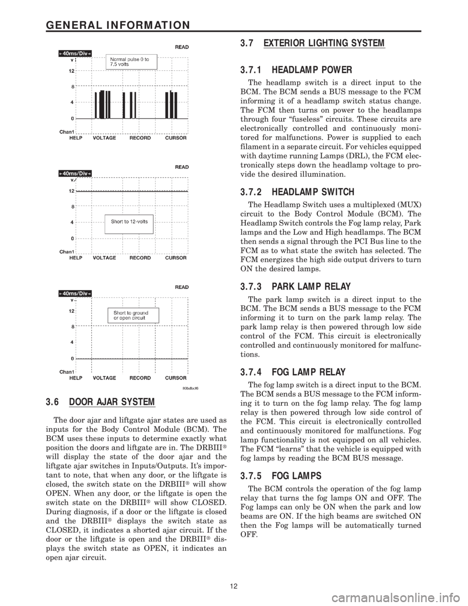
ineffective to try and measure the bus activity witha conventional voltmeter. The preferred method is
to use the DRBIIItlab scope. The 12v square wave
selection on the 20-volt scale provides a good view of
the bus activity. Voltage on the bus should pulse
between zero and about seven and a half volts.
Refer to the following figure for some typical dis-
plays.
The PCI Bus failure modes are broken down into
two categories. Complete PCI Bus Communication
Failure and individual module no response. Causes
of complete PCI Bus Communication Failure in-
clude a short to ground or battery on the PCI
circuit. Individual module no response can be
caused by an open circuit at either the Diagnostic
Junction Port or the module, or an open battery or
ground circuit to the affected module.
Symptoms of a complete PCI Bus Communication
Failure would include but are not limited to:
²All gauges on the MIC stay at zero
²All telltales on MIC illuminate
²MIC backlighting at full intensity
²Dashed lines in the overhead console ambient
temperature display
²No response received from any module on the PCI
bus (except the PCM)
²No start (if equipped with Sentry Key Immobi-
lizer)
Symptoms of Individual module failure could
include any one or more of the above. The difference
would be that at least one or more modules would
respond to the DRBIIIt.
Diagnosis starts with symptom identification. If a
complete PCI Bus Communication Failure is sus-
pected, begin by identifying which modules the
vehicle is equipped with and then attempt to get a
response from the modules with the DRBIIIt.Ifany
modules are responding, the failure is not related to
the total bus, but can be caused by one or more
modules PCI circuit or power supply and ground
circuits. The DRBIIItmay display ªBUS +/- SIG-
NAL OPENº or ªNO RESPONSEº to indicate a
communication problem. These same messages will
be displayed if the vehicle is not equipped with that
particular module. The CCD error message is a
default message used by the DRBIIItand in no way
indicates whether or not the PCI bus is operational.
The message is only an indication that a module is
either not responding or the vehicle is not equipped.
11
GENERAL INFORMATION
Page 41 of 4284
3.6 DOOR AJAR SYSTEM
The door ajar and liftgate ajar states are used as
inputs for the Body Control Module (BCM). The
BCM uses these inputs to determine exactly what
position the doors and liftgate are in. The DRBIIIt
will display the state of the door ajar and the
liftgate ajar switches in Inputs/Outputs. It's impor-
tant to note, that when any door, or the liftgate is
closed, the switch state on the DRBIIItwill show
OPEN. When any door, or the liftgate is open the
switch state on the DRBIIItwill show CLOSED.
During diagnosis, if a door or the liftgate is closed
and the DRBIIItdisplays the switch state as
CLOSED, it indicates a shorted ajar circuit. If the
door or the liftgate is open and the DRBIIItdis-
plays the switch state as OPEN, it indicates an
open ajar circuit.
3.7 EXTERIOR LIGHTING SYSTEM
3.7.1 HEADLAMP POWER
The headlamp switch is a direct input to the
BCM. The BCM sends a BUS message to the FCM
informing it of a headlamp switch status change.
The FCM then turns on power to the headlamps
through four ªfuselessº circuits. These circuits are
electronically controlled and continuously moni-
tored for malfunctions. Power is supplied to each
filament in a separate circuit. For vehicles equipped
with daytime running Lamps (DRL), the FCM elec-
tronically steps down the headlamp voltage to pro-
vide the desired illumination.
3.7.2 HEADLAMP SWITCH
The Headlamp Switch uses a multiplexed (MUX)
circuit to the Body Control Module (BCM). The
Headlamp Switch controls the Fog lamp relay, Park
lamps and the Low and High headlamps. The BCM
then sends a signal through the PCI Bus line to the
FCM as to what state the switch has selected. The
FCM energizes the high side output drivers to turn
ON the desired lamps.
3.7.3 PARK LAMP RELAY
The park lamp switch is a direct input to the
BCM. The BCM sends a BUS message to the FCM
informing it to turn on the park lamp relay. The
park lamp relay is then powered through low side
control of the FCM. This circuit is electronically
controlled and continuously monitored for malfunc-
tions.
3.7.4 FOG LAMP RELAY
The fog lamp switch is a direct input to the BCM.
The BCM sends a BUS message to the FCM inform-
ing it to turn on the fog lamp relay. The fog lamp
relay is then powered through low side control of
the FCM. This circuit is electronically controlled
and continuously monitored for malfunctions. Fog
lamp functionality is not equipped on all vehicles.
The FCM ªlearnsº that the vehicle is equipped with
fog lamps by reading the BCM BUS message.
3.7.5 FOG LAMPS
The BCM controls the operation of the fog lamp
relay that turns the fog lamps ON and OFF. The
Fog lamps can only be ON when the park and low
beams are ON. If the high beams are switched ON
then the Fog lamps will be automatically turned
OFF.
12
GENERAL INFORMATION
Page 44 of 4284
Front and rear blower relay
The blower control switch is part of the Automatic
Temperature Control (ATC) or A/C-Heater Control
Module, (Manual Temp). When the blower switch is
turned on, the ATC or A/C-Heater Control Module
sends a PCI Bus message to the FCM. The front and
rear blower relay is then powered through low side
control on pin 30 of the FCM. The relay provides the
high side to the blower motor, and the blower speed
is governed through low side control in the ATC or
A/C-Heater Control Module. This circuit is electron-
ically controlled and continuously monitored for
malfunctions.
Name Brand Speakers (NBS) relay
The NBS relay operates through the vehicle bus
interface between the radio and the FCM. When the
radio is turned on, the radio sends a PCI Bus
message to the FCM. The NBS relay is then pow-
ered on through low side control on pin 11 of the
FCM. The relay supplies power to the amplified
speaker, and ground is supplied through the radio.
This circuit is electronically controlled and contin-
uously monitored for malfunctions.
Electronic Back Light (EBL) relay
The rear defrost switch is part of the Automatic
Temperature Control or A/C-Heater Control Module
(Manual Temp). When the ignition switch is in the
RUN position and the rear defrost switch is turned
on, the ATC or A/C-Heater Control Module sends a
PCI Bus message to the FCM. The EBL run only
relay is then powered through low side control on
pin 31 of the FCM. The relay provides the high side
to the rear window defrost grid, and ground is
attached to the vehicle body. The FCM will only
allow the rear defrost to operate in the RUN posi-
tion. This circuit is electronically controlled and
continuously monitored for malfunctions.
Cabin Heater Relay
When the ignition is in Run, the FCM monitors
the PCI bus for the Cabin Heater Activation re-
quest. The A/C ± Heater Control Module initiates
this request only when all conditions for Cabin
Heater activation are favorable. The request carries
the status bit that the FCM requires to activate its
Cabin Heater Assist Control output. This output is
a low side driver (coming from FCM pin 15) which
supplies a ground signal to the Cabin Heater (pin
5). When the Cabin Heater receives this ground
signal input, it interprets this as an activation
signal. The FCM low side driver is also capable of
diagnostic sensing. The driver will sense an open
circuit when the driver is off, and will sense a short
to voltage when the driver is on. The FCM will set
DTCs for both of these types of faults. For addi-
tional information, refer to Cabin Heater under
General Information and Diagnostic Procedures in
the manual.3.8.3 ELECTRICAL INPUTS
Headlamp battery supplies1&2Ð12 volt
input on pins 1 and 2. Battery supply voltage for
switching headlamp circuits only.
Module battery supply Ð12 volt input on pin 9.
Battery supply voltage for all other FCM opera-
tions.
Power ground ÐGround source on pin 8 for all
FCM operations.
Ignition switch RUN or START position status
Ð12 volt input on pin 37. Allows the FCM to
determine the ignition switch status for related
FCM operations.
Ignition switch START only status Ð12 volt
input on pin 19. Allows the FCM to discriminate
between RUN/START input and START for related
FCM operations.
PCI Bus ÐApproximately 7.5 volt input on pin 22.
Allows the FCM to communicate with other mod-
ules on the vehicle bus.
Stop lamp Switch status Ð12 volt input on pin
44. Provides for brake shift interlock function.
Horn Switch ÐGround input on pin 17. Primary
means for engaging the horn.
Back-up switch ÐGround input on pin 39. Input
is converted to a PCI Bus status message for use by
other modules.
Wiper park switch ÐGround input on pin 16.
Used to determine park placement of wipers. Also
used as feedback to FCM to determine correct
operating mode of wipers.
Washer fluid level switch ÐGround input to
pull-up on pin 18. Ground is switched into the
circuit when washer bottle fluid level is low.
Brake fluid level switch ÐGround input to
pull-up on pin 36. Ground is switched into the
circuit when brake fluid level is low.
Ambient temperature sensor ÐResistive input
to pull-up on pin 25. Corresponding voltage level is
converted to a PCI Bus message for use by other
modules on the bus.
Right park lamp outage Ð12 volt input on pin
21. Used to determine if right park lamp circuit is
operating properly.
Left park lamp outage Ð12 volt input on pin 41.
Used to determine if left park lamp circuit is
operating properly.
Battery IOD Ð12 volt input on pin 20. The FCM
enters a low power consumption mode when the
ignition is turned OFF. This low current draw
battery supply keeps the microprocessor function-
ing in the low power mode.
Battery (+) connection detection Ð12 volt
input on pin 38. The battery connection on the PDC
incorporates the use of an internal switch to deter-
mine if the connector is properly mated and the
Connector Positive Assurance (CPA) is engaged. If
15
GENERAL INFORMATION
Page 50 of 4284

ating and the combustion air fan operation is sus-
pended for 3 seconds. Subsequently, the combustion
air fan speed is increased in two ramps within 56
seconds to nearly full load operation. After a stabi-
lization phase of 15 seconds, the combustion air fan
speed is again increased in a ramp within 50
seconds to nearly full load. After reaching full load
fuel delivery, the glow plug is deactivated and the
combustion air fan operation is increased to full
load. During the subsequent 45 seconds, as well as
in normal operation, the glow plug functions as a
flame sensor to monitor the flame condition. After
all these events, the automatically controlled heat-
ing operation starts.
In case of a no flame or a flame out condition, a
restart is automatically initiated. If the no flame
condition persists, fuel delivery is stopped and the
heater enters an error lockout mode with a run-
down of the combustion air fan. This will set one or
more DTCs in the DCHA Control's memory. If six
continuous attempts to start the heater fail due to
one or more faults in the DCHA system, the heater
enters a heater lockout mode. This will set DTC
B1813 along with any other fault(s) that the DCHA
Control identified.
3.10.3.2 HEATING
During the automatically controlled heating op-
eration, when the coolant temperature reaches
72ÉC (162ÉF), the heater will switch to a part load
operation. When the coolant temperature reaches
75ÉC (167ÉF) or if the heater runs for longer than 76
minutes the heater will switch to a control idle
period. If the coolant temperature drops to 71ÉC
(160ÉF) during a control idle period, the heater will
perform a regular starting sequence into full load
operation. A drop in coolant temperature to 65ÉC
(149ÉF) during part load operation will cause the
heater to switch to a full load operation.
3.10.3.3 DEACTIVATION
The DCHA will deactivate if the:
²engine is turned off.
²coolant temperature reaches 75ÉC (167ÉF).
²heater runs longer than 76 minutes.
²fuel tank has less than 1/8 of a tank of fuel.
²Power switch on the A/C ± Heater Control Module
is off.
²Blend Control on the A/C ± Heater Control Mod-
ule is set below 75% reheat.
When the heater is deactivated, the combustion
stops and a run-down sequence begins. During the
run-down sequence, the combustion air fan contin-
ues operation to cool down the heater. The fan is
automatically switched off after the run-down se-
quence is complete. The run-down time and thecombustion air fan speed depend on the heater
operating condition at the time of deactivation.
Run-down time is approximately 175 seconds when
deactivated in full load operation and approxi-
mately 100 seconds when deactivated in part load
operation.
3.10.4 DIAGNOSTICS
The DCHA is fully addressable with the DRBIIIt.
System tests include a Field Mode Test to activate
the DCHA for diagnostic testing purposes. The
DCHA Control will store up to three DTCs in its
memory. If the Controller detects a new fault in the
DCHA system, one that is not already stored in its
memory, it will clear the oldest of the three stored
DTCs, and it will store the new fault's DTC. If the
Controller detects a reoccurrence of a stored fault, it
will overwrite that fault's DTC with the most recent
occurrence.
3.11 INSTRUMENT CLUSTER
The Instrument Cluster receives and sends mes-
sages to other modules via the PCI bus circuit. The
indicator lamps will illuminate briefly for a bulb
check when the ignition is turned from off to run.
All of the gauges receive their information via the
PCI bus from the powertrain control module and
body control module.
The gauges and the LEDs are not individually
replaceable thereby requiring complete replace-
ment of the Instrument Cluster if a repair is neces-
sary. In the event that the Instrument Cluster loses
communication with other modules on the PCI bus,
the cluster will display ªno busº in the VF display.
The Trip/Reset button is used to switch the dis-
play from trip to total mileage. Holding the button
when the display is in the trip mode will reset the
trip mileage. This button is also used to put the
cluster in self-diagnostic mode. The odometer dis-
play uses blue-green vacuum fluorescent digital
characters.
On base vehicles, the Instrument Cluster has
three gauges: Speedometer, Fuel and Engine Cool-
ant Temperature. A red dot moves transversely
through openings in the Instrument Cluster face
(P-R-N-D-2-1) to indicate the gear selected.
With all other models, the Instrument Cluster
also includes a Tachometer and uses a vacuum-
fluorescent shift indicator.
The odometer display and door/liftgate ajar indi-
cators turn on when a door is opened to assist both
the customer and service technician to view the
odometer without turning the ignition on.
21
GENERAL INFORMATION