Page 41 of 88
Downloaded from www.Manualslib.com manuals search engine
41
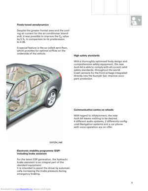
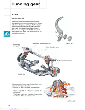
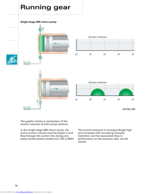
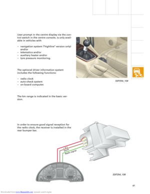
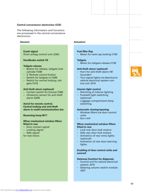
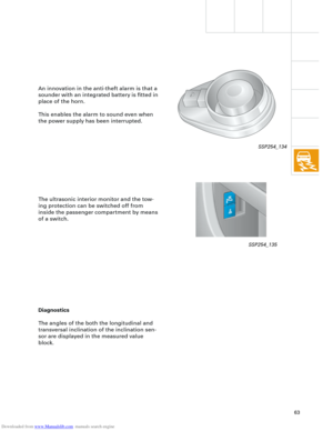
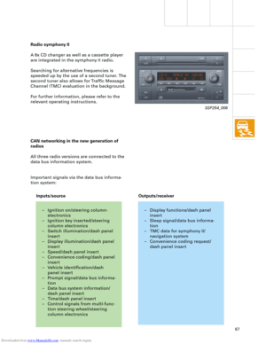
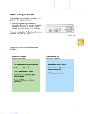
In order to ensure good signal reception for
the radio clock, the receiver is installed in the
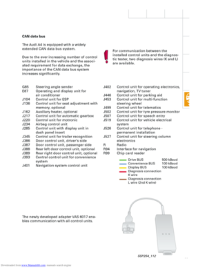
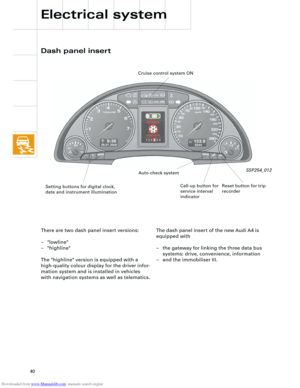
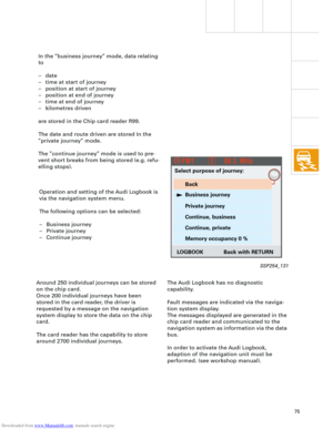
rear bumper bar. User prompt in the centre display via the con-
trol switch in the centre console, is only avail-
able in vehicles with
– navigation system ("highline" version only)
and/or
– telematics and/or
– auxiliary heater and/or
– tyre pressure monitoring.
The optional driver information system
includes the following functions:
– radio clock
– auto-check system
– on-board computer.
The km range is indicated in the basic ver-
sion.
Ear
th
Radio signal
+ 5
V
SSP254_104
SSP254_108
Page 42 of 88
Downloaded from www.Manualslib.com manuals search engine
42
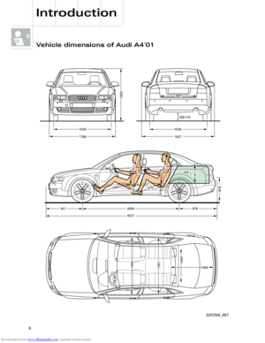
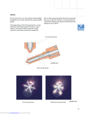
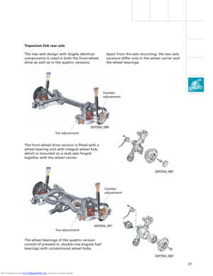
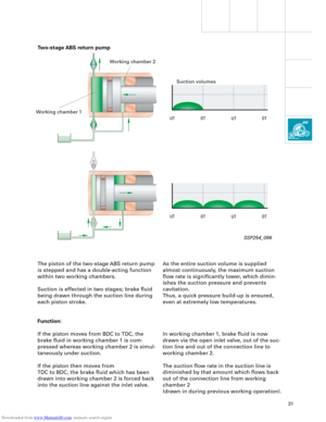
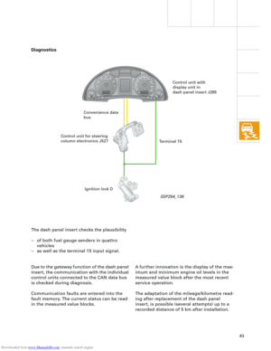
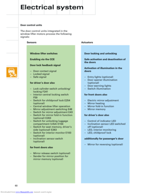
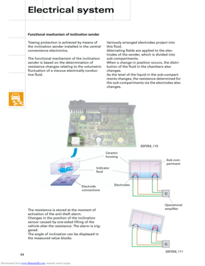
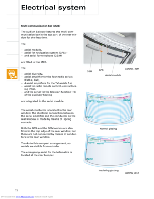
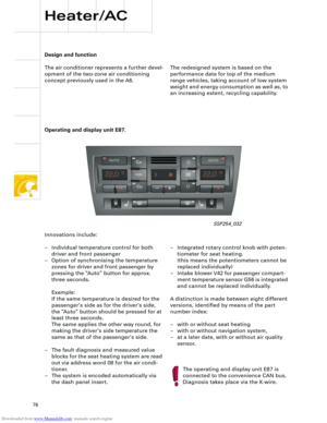
The Audi A4 quattro is equipped with two fuel
gauge senders G and G169.
Sender G registers the lower, and sender
G169 the upper partial volume in the fuel
tank.
The signals from senders G and G169 are
evaluated separately. The calculated litre
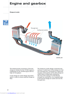
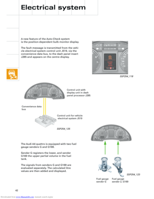
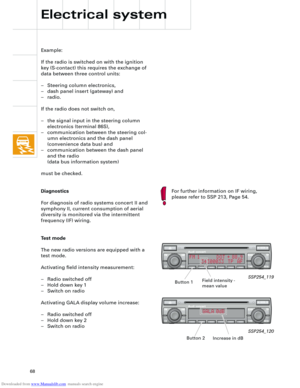
values are then added and displayed. A new feature of the Auto-Check system
is the position-dependent bulb monitor display.
The fault message is transmitted from the vehi-
cle electrical system control unit J519, via the
convenience data bus, to the dash panel insert
J285 and appears on the centre display.
Electrical system
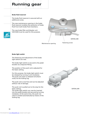
Fuel gauge
sender 2, G169 Fuel gauge
sender G
SSP254_123
Control unit with
display unit in dash
panel processor J285
Control unit for vehicle
electrical system J519 Convenience data
bus
SSP254_118
SSP254_125
Page 43 of 88

Downloaded from www.Manualslib.com manuals search engine
43
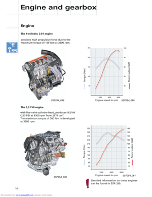
A further innovation is the display of the max-
imum and minimum engine oil levels in the
measured value block after the most recent
service operation.
The adaptation of the mileage/kilometre read-
ing after replacement of the dash panel
insert, is possible (several attempts) up to a
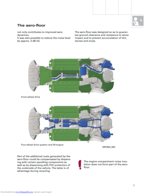
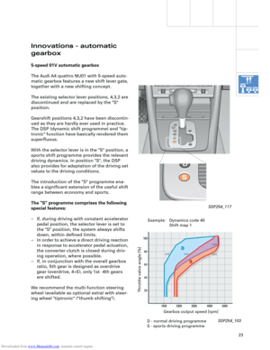
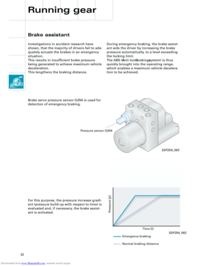
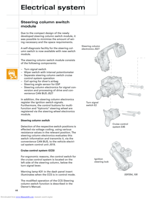
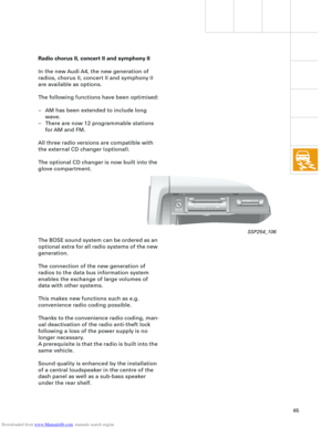
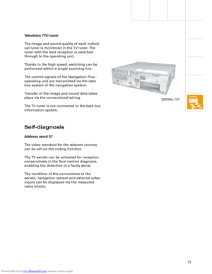
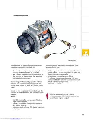
recorded distance of 5 km after installation. The dash panel insert checks the plausibility
– of both fuel gauge senders in quattro
vehicles
– as well as the terminal 15 input signal.
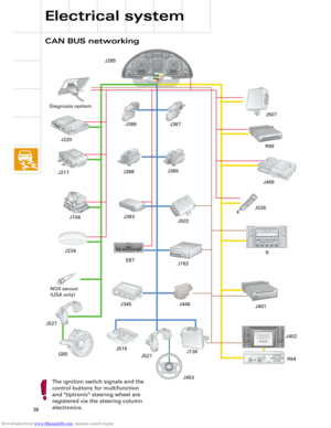
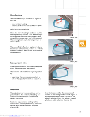
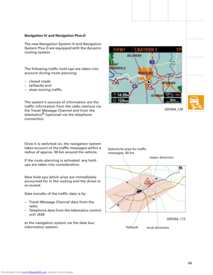
Due to the gateway function of the dash panel
insert, the communication with the individual
control units connected to the CAN data bus
is checked during diagnosis.
Communication faults are entered into the
fault memory. The current status can be read
in the measured value blocks.
Control unit with
display unit in
dash panel insert J285
Control unit for steering
column electronics J527
Ignition lock D Convenience data
bus
Terminal 15
Diagnostics
SSP254_138
Page 44 of 88

Downloaded from www.Manualslib.com manuals search engine
44
Electrical system
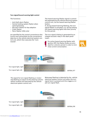
Steering column switch
module
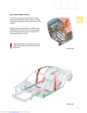
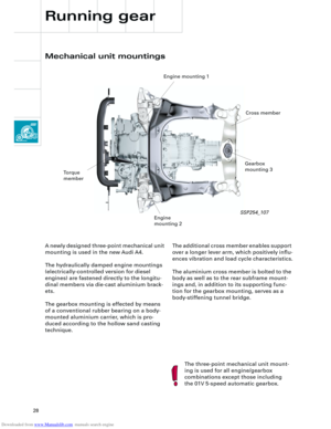
Due to the compact design of the newly
developed steering column switch module, it
was possible to minimise the amount of wir-
ing necessary and the space requirements.
A self-diagnosis facility for the steering col-
umn switch is now available with new switch
module.
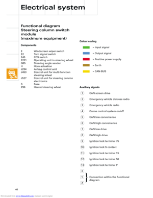
The steering column switch module consists
of the following components:
– Turn signal switch
– Wiper switch with interval potentiometer
– Separate steering column switch cruise
control system operation
– Coil spring for diver's airbag
– Steering angle sensor for ESP
– Steering column electronics for signal con-
version and processing of drive and con-
venience CAN BUS J527
In addition, the steering column electronics
register the ignition switch signals.
Furthermore, the control buttons for multi-
function and "tiptronic" steering wheel are
registered via the steering wheel electronics
module.
Steering column switch
Detection of the respective switch positions is
effected via voltage coding, using various
resistance values in the relevant position. The
steering column electronics evaluates this
switch information and transmits it, via the
convenience CAN BUS, to the vehicle electri-
cal system control unit J519.
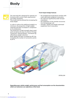
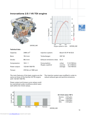
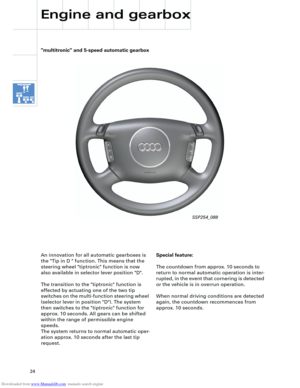
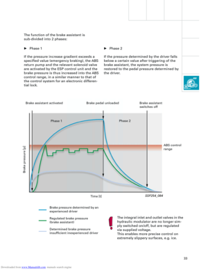
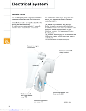
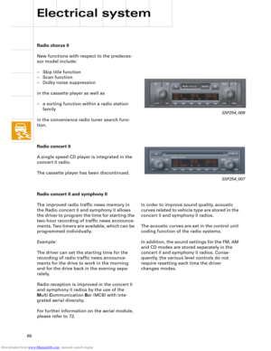
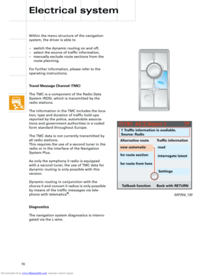
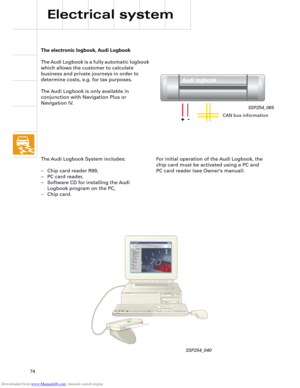
Cruise control system (CCS)
For ergonomic reasons, the control switch for
the cruise control system is located on the
left side of the steering column, below the
turn signal lever.
Warning lamp K31 in the dash panel insert
illuminates when the CCS is in control mode.
The modified operation of the CCS Steering
column switch function is described in the
Owner's Manual.
Cruise control
system E45
Ignition
steering lock Steering column
electronics J527
Turn signal
switch E2
SSP254_105
Page 45 of 88

Downloaded from www.Manualslib.com manuals search engine
45
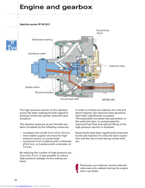
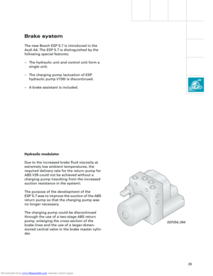
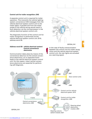
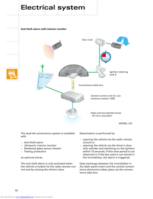
Steering angle sender G85
The determination of steering angle is per-
formed via optical elements in the steering
column electronics J527 and is supplied to
the drive CAN BUS.
The current steering angle position is thus
made available to the ESP control unit.
The steering column switch module
must always be coded.
For further information on the optical
steering angle sensor, please refer to
SSP 204.
Self-diagnosis
Communication between the diagnostic
tester and the steering column electronics
J527 is effected by means of the convenience
data bus via the central convenience electron-
ics J393, as no separate K wire is connected
to the steering column electronics.. (see
graphic 254 018 on Page 57)
The steering column electronics module with
operating unit for "tiptronic", multi-functions,
horn etc., is incorporated in the self-diagnosis.
Address word 16
After the addressing, the tester answers with
the text "steering column electronics".
Wiper
switch E
Steering angle
sensor G85
Steering column electronics
module J453 with operating
unit E221
Ignition lock registration
The signals from the terminals:
– P parking light
– 86s ignition key contact
– 75 Load-reduction relay
– 15 ignition ON
– 50 starter
are transmitted to the steering column elec-
tronics J527 via conventional wiring. The
switch positions of the ignition lock are pre-
pared by the electronics, supplied to the con-
venience CAN bus and then transmitted via
the gateway to the drive and infotainment
CAN bus systems.
Coil spring
RT
SSP254_014
Page 46 of 88
Downloaded from www.Manualslib.com manuals search engine
46
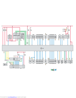
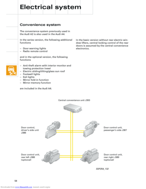
Auxiliary signals
1 CAN screen drive
2 Emergency vehicle distress radio
3 Emergency vehicle radio
4 Cruise control system on/off
5 CAN low convenience
6 CAN high convenience
7 CAN low drive
8 CAN high drive
9 Ignition lock terminal 75
10 Ignition lock S contact
11 Ignition lock terminal 15
12 Ignition lock terminal 50
13 Ignition lock terminal P
X
Y Connection within the functional
diagram
Z
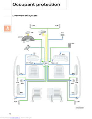
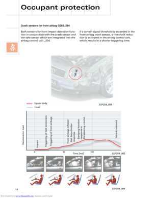
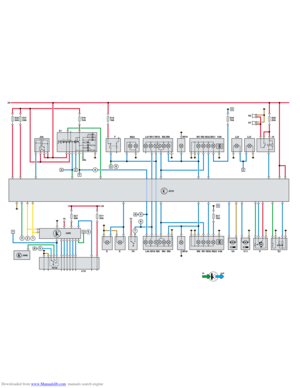
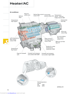
Electrical system
Functional diagram
Steering column switch
module
(maximum equipment)
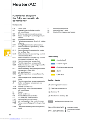
Components
E Windscreen wiper switch
E2 Turn signal switch
E45 CCS switch
E221 Operating unit in steering wheel
G85 Steering angle sender
H Horn actuation
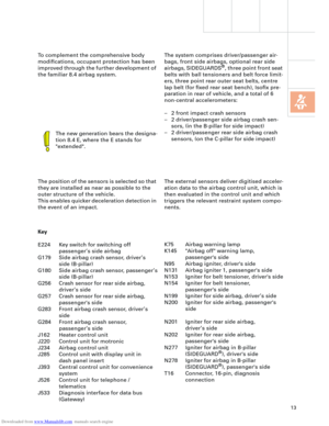
J234 Airbag control unit
J453 Control unit for multi-function
steering wheel
J527 Control unit for steering column
electronics
S Fuse
Z36 Heated steering wheel
Colour coding
= Input signal
= Output signal
= Positive power supply
= Earth
= CAN-BUS
{
Page 47 of 88
Downloaded from www.Manualslib.com manuals search engine 31
J527
31
S13/
10A
E
E45
YX
G85
J453R/T
J234
1
2
3
4
5
6
7
8
9
10
11
12
13
Z
X
E2 E221
Y
Z
+
Z36H
in out
Page 48 of 88

Downloaded from www.Manualslib.com manuals search engine
48
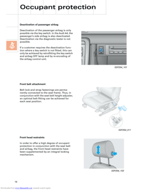
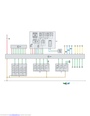
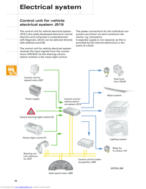
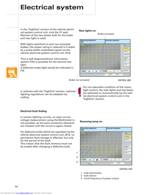
The control unit for vehicle electrical system
J519 is the newly developed electronic central
electrics and comprises a comprehensive
self-diagnosis, which can be selected directly
with address word 09.
The control unit for vehicle electrical system
receives the input signals from the conven-
ience CAN BUS via the steering column
switch module or the rotary light control.
Pb1J0 915 105 A 1J0 915 105 A
C C
The power connections for the individual con-
sumers are driven via semi-conductor ele-
ments, e.g. transistors.
A separate supply is not required, as this is
provided by the internal electronics in the
event of a fault.
J4
Dual tone-
horn H2/H4 Control unit for
speech entry J507
Power supply
Hazard warning lights switch E3
Steering col-
umn electron-
ics J527 Rotary light control E1
Wiper system
Lighting system
Dash panel insert J285Control unit for trailer
recognition J345 Control unit for
vehicle electri-
cal system J519
Relay for
X contact J18
Electrical system
Control unit for vehicle
electrical system J519
SSP254_068