2001 AUDI A4 wheel
[x] Cancel search: wheelPage 39 of 88
Downloaded from www.Manualslib.com manuals search engine
39
CAN data bus
The Audi A4 is equipped with a widely
extended CAN data bus system.
Due to the ever increasing number of control
units installed in the vehicle and the associ-
ated requirement for data exchange, the
importance of the CAN data bus system
increases significantly.For communication between the
installed control units and the diagnos-
tic tester, two diagnosis wires (K and L)
are available.
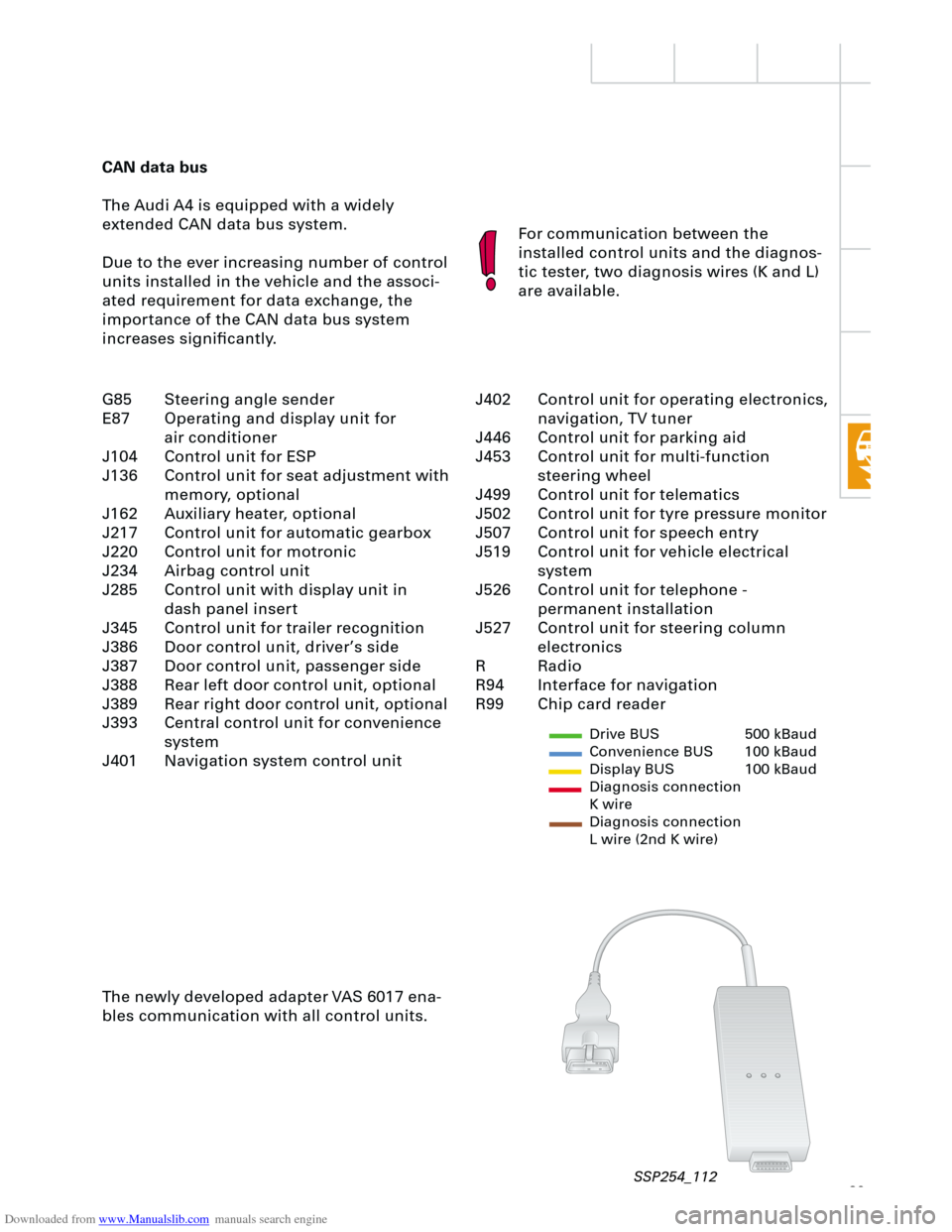
The newly developed adapter VAS 6017 ena-
bles communication with all control units.
Drive BUS 500 kBaud
Convenience BUS 100 kBaud
Display BUS 100 kBaud
Diagnosis connection
K wire
Diagnosis connection
L wire (2nd K wire)
J402 Control unit for operating electronics,
navigation, TV tuner
J446 Control unit for parking aid
J453 Control unit for multi-function
steering wheel
J499 Control unit for telematics
J502 Control unit for tyre pressure monitor
J507 Control unit for speech entry
J519 Control unit for vehicle electrical
system
J526 Control unit for telephone -
permanent installation
J527 Control unit for steering column
electronics
R Radio
R94 Interface for navigation
R99 Chip card reader G85 Steering angle sender
E87 Operating and display unit for
air conditioner
J104 Control unit for ESP
J136 Control unit for seat adjustment with
memory, optional
J162 Auxiliary heater, optional
J217 Control unit for automatic gearbox
J220 Control unit for motronic
J234 Airbag control unit
J285 Control unit with display unit in
dash panel insert
J345 Control unit for trailer recognition
J386 Door control unit, driver’s side
J387 Door control unit, passenger side
J388 Rear left door control unit, optional
J389 Rear right door control unit, optional
J393 Central control unit for convenience
system
J401 Navigation system control unit
SSP254_112
Page 44 of 88
Downloaded from www.Manualslib.com manuals search engine
44
Electrical system
Steering column switch
module
Due to the compact design of the newly
developed steering column switch module, it
was possible to minimise the amount of wir-
ing necessary and the space requirements.
A self-diagnosis facility for the steering col-
umn switch is now available with new switch
module.
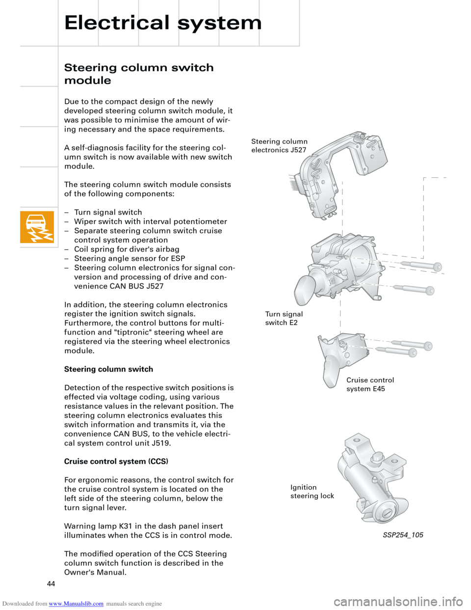
The steering column switch module consists
of the following components:
– Turn signal switch
– Wiper switch with interval potentiometer
– Separate steering column switch cruise
control system operation
– Coil spring for diver's airbag
– Steering angle sensor for ESP
– Steering column electronics for signal con-
version and processing of drive and con-
venience CAN BUS J527
In addition, the steering column electronics
register the ignition switch signals.
Furthermore, the control buttons for multi-
function and "tiptronic" steering wheel are
registered via the steering wheel electronics
module.
Steering column switch
Detection of the respective switch positions is
effected via voltage coding, using various
resistance values in the relevant position. The
steering column electronics evaluates this
switch information and transmits it, via the
convenience CAN BUS, to the vehicle electri-
cal system control unit J519.
Cruise control system (CCS)
For ergonomic reasons, the control switch for
the cruise control system is located on the
left side of the steering column, below the
turn signal lever.
Warning lamp K31 in the dash panel insert
illuminates when the CCS is in control mode.
The modified operation of the CCS Steering
column switch function is described in the
Owner's Manual.
Cruise control
system E45
Ignition
steering lock Steering column
electronics J527
Turn signal
switch E2
SSP254_105
Page 46 of 88
Downloaded from www.Manualslib.com manuals search engine
46
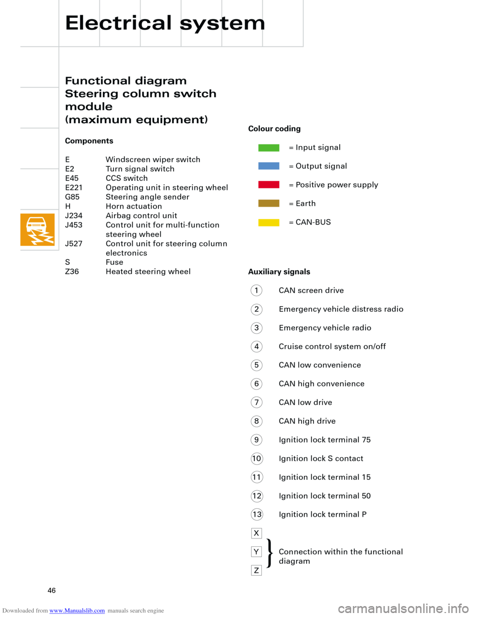
Auxiliary signals
1 CAN screen drive
2 Emergency vehicle distress radio
3 Emergency vehicle radio
4 Cruise control system on/off
5 CAN low convenience
6 CAN high convenience
7 CAN low drive
8 CAN high drive
9 Ignition lock terminal 75
10 Ignition lock S contact
11 Ignition lock terminal 15
12 Ignition lock terminal 50
13 Ignition lock terminal P
X
Y Connection within the functional
diagram
Z
Electrical system
Functional diagram
Steering column switch
module
(maximum equipment)
Components
E Windscreen wiper switch
E2 Turn signal switch
E45 CCS switch
E221 Operating unit in steering wheel
G85 Steering angle sender
H Horn actuation
J234 Airbag control unit
J453 Control unit for multi-function
steering wheel
J527 Control unit for steering column
electronics
S Fuse
Z36 Heated steering wheel
Colour coding
= Input signal
= Output signal
= Positive power supply
= Earth
= CAN-BUS
{
Page 56 of 88
Downloaded from www.Manualslib.com manuals search engine
56
Electrical system
The windscreen wash/wipe relays are inte-
grated into the vehicle electrical system
control unit J519.
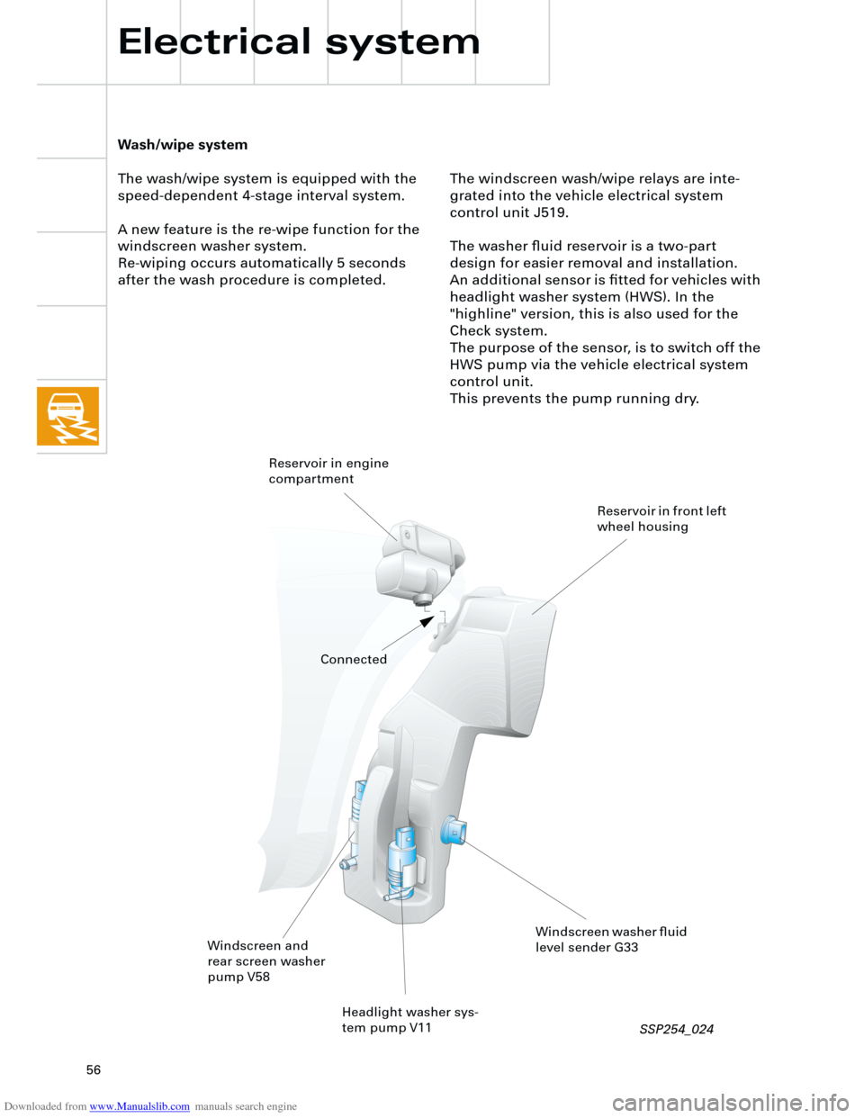
The washer fluid reservoir is a two-part
design for easier removal and installation.
An additional sensor is fitted for vehicles with
headlight washer system (HWS). In the
"highline" version, this is also used for the
Check system.
The purpose of the sensor, is to switch off the
HWS pump via the vehicle electrical system
control unit.
This prevents the pump running dry.
Wash/wipe system
The wash/wipe system is equipped with the
speed-dependent 4-stage interval system.
A new feature is the re-wipe function for the
windscreen washer system.
Re-wiping occurs automatically 5 seconds
after the wash procedure is completed.
Headlight washer sys-
tem pump V11
Windscreen and
rear screen washer
pump V58
Windscreen washer fluid
level sender G33 Reservoir in engine
compartment
Reservoir in front left
wheel housing
Connected
SSP254_024
Page 57 of 88
Downloaded from www.Manualslib.com manuals search engine
57
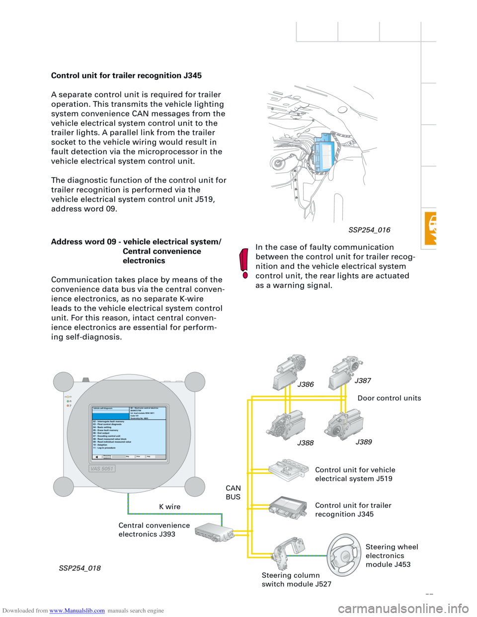
Control unit for trailer recognition J345
A separate control unit is required for trailer
operation. This transmits the vehicle lighting
system convenience CAN messages from the
vehicle electrical system control unit to the
trailer lights. A parallel link from the trailer
socket to the vehicle wiring would result in
fault detection via the microprocessor in the
vehicle electrical system control unit.
The diagnostic function of the control unit for
trailer recognition is performed via the
vehicle electrical system control unit J519,
address word 09.
In the case of faulty communication
between the control unit for trailer recog-
nition and the vehicle electrical system
control unit, the rear lights are actuated
as a warning signal.
RT
Address word 09 - vehicle electrical system/
Central convenience
electronics
Communication takes place by means of the
convenience data bus via the central conven-
ience electronics, as no separate K-wire
leads to the vehicle electrical system control
unit. For this reason, intact central conven-
ience electronics are essential for perform-
ing self-diagnosis.
K wireCAN
BUS
Central convenience
electronics J393
SSP254_018J389
J388J387
J386
Door control units
Control unit for vehicle
electrical system J519
Control unit for trailer
recognition J345
09 – Electronic central electrics
8E0907279B
int. load module RDW 0811
Code 101
Dealership No. 6803
02 - Interrogate fault memory
03 - Final control diagnosis
04 - Basic setting
05 - Erase fault memory
06 - End output
07 - Encoding control unit
08 - Read measured value block
09 - Read individual measured value
10 - Adaption
11 - Log-in procedure
Measuring
equipmentSkip PrintHelp
Steering column
switch module J527
Vehicle self-diagnosis
Steering wheel
electronics
module J453
SSP254_016
VAS 5051
Page 67 of 88
Downloaded from www.Manualslib.com manuals search engine
67
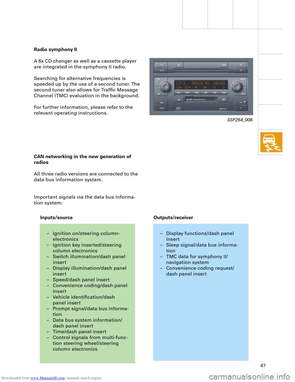
Radio symphony II
A 6x CD changer as well as a cassette player
are integrated in the symphony II radio.
Searching for alternative frequencies is
speeded up by the use of a second tuner. The
second tuner also allows for Traffic Message
Channel (TMC) evaluation in the background.
For further information, please refer to the
relevant operating instructions.
CAN networking in the new generation of
radios
All three radio versions are connected to the
data bus information system.
Important signals via the data bus informa-
tion system:
SSP254_006
– Ignition on/steering column-
electronics
– Ignition key inserted/steering
column electronics
– Switch illumination/dash panel
insert
– Display illumination/dash panel
insert
– Speed/dash panel insert
– Convenience coding/dash panel
insert
– Vehicle identification/dash
panel insert
– Prompt signal/data bus informa-
tion
– Data bus system information/
dash panel insert
– Time/dash panel insert
– Control signals from multi-func-
tion steering wheel/steering
column electronics– Display functions/dash panel
insert
– Sleep signal/data bus informa-
tion
– TMC data for symphony II/
navigation system
– Convenience coding request/
dash panel insert
Inputs/sourceOutputs/receiver
Page 71 of 88
Downloaded from www.Manualslib.com manuals search engine
71
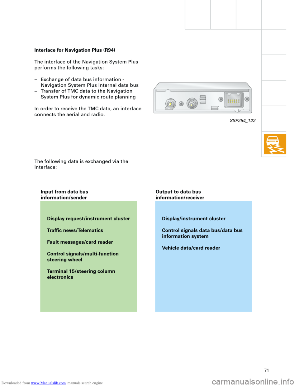
Interface for Navigation Plus (R94)
The interface of the Navigation System Plus
performs the following tasks:
– Exchange of data bus information -
Navigation System Plus internal data bus
– Transfer of TMC data to the Navigation
System Plus for dynamic route planning
In order to receive the TMC data, an interface
connects the aerial and radio.
The following data is exchanged via the
interface:
Display request/instrument cluster
Traffic news/Telematics
Fault messages/card reader
Control signals/multi-function
steering wheel
Terminal 15/steering column
electronicsDisplay/instrument cluster
Control signals data bus/data bus
information system
Vehicle data/card reader Input from data bus
information/senderOutput to data bus
information/receiver
SSP254_122