Page 34 of 121
INSTRUMENT AND CONTROL FUNCTIONS
3-20
3
2. Remove the valve cap from each
fork leg.
3. Check the air pressure using the
air pressure gauge in the owner’s
tool kit, and adjust it if necessary.
Increasing the air pressure in-
creases the spring preload, de-
creasing the air pressure
decreases the spring preload.
To increase the air pressure, use
an air pump or compressed air.
To decrease the air pressure, re-
lease the air by pushing the valve.
EC000012
CAUTION:@ Never exceed the maximum pres-
sure, or oil seal damage may occur. @4. Install the valve caps securely.
1. Front fork air valve cap
Spring preload (air pressure):
Minimum/Standard:
0 kPa (0 kg/cm
2, 0 bar)
Maximum:
50 kPa (0.5 kg/cm2, 0.5 bar)
E_5jc_Functions.fm Page 20 Saturday, October 16, 1999 1:08 PM
Page 35 of 121

INSTRUMENT AND CONTROL FUNCTIONS
3-21
3
EAU01879*
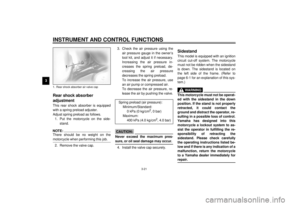
Rear shock absorber
adjustmentThis rear shock absorber is equipped
with a spring preload adjuster.
Adjust spring preload as follows.
1. Put the motorcycle on the side-
stand.NOTE:@ There should be no weight on the
motorcycle when performing this job. @2. Remove the valve cap.3. Check the air pressure using the
air pressure gauge in the owner’s
tool kit, and adjust it if necessary.
Increasing the air pressure in-
creases the spring preload, de-
creasing the air pressure
decreases the spring preload.
To increase the air pressure, use
an air pump or compressed air.
To decrease the air pressure, re-
lease the air by pushing the valve.
EC000012
CAUTION:@ Never exceed the maximum pres-
sure, or oil seal damage may occur. @4. Install the valve cap securely.
EAU00330
SidestandThis model is equipped with an ignition
circuit cut-off system. The motorcycle
must not be ridden when the sidestand
is down. The sidestand is located on
the left side of the frame. (Refer to
page 6-1 for an explanation of this sys-
tem.)
EW000044
WARNING
@ This motorcycle must not be operat-
ed with the sidestand in the down
position. If the stand is not properly
retracted, it could contact the
ground and distract the operator, re-
sulting in a possible loss of control.
Yamaha has designed into this
motorcycle a lockout system to as-
sist the operator in fulfilling the re-
sponsibility of retracting the
sidestand. Please check carefully
the operating instructions listed be-
low and if there is any indication of a
malfunction, return the motorcycle
to a Yamaha dealer immediately for
repair. @
1. Rear shock absorber air valve cap
Spring preload (air pressure):
Minimum/Standard:
0 kPa (0 kg/cm
2, 0 bar)
Maximum:
400 kPa (4.0 kg/cm
2, 4.0 bar)
E_5jc_Functions.fm Page 21 Saturday, October 16, 1999 1:08 PM
Page 57 of 121

5-1
5
EAU01114
5-PRE-OPERATION CHECKSOwners are personally responsible for their vehicle’s condition. Your motorcycle’s vital functions can start to deteriorate
quickly and unexpectedly, even if it remains unused (for instance, if it is exposed to the elements). Any damage, fluid leak or
loss of tire pressure could have serious consequences. Therefore, it is very important that, in addition to a thorough visual in-
spection, you check the following points before each ride.
EAU00340
PRE-OPERATION CHECK LIST
ITEM CHECKS PAGE
Front brake• Check operation, fluid level and vehicle for fluid leakage.
• Fill with DOT 4 brake fluid if necessary.
7-23 ~ 7-26
Rear brake• Check operation, fluid level and vehicle for fluid leakage.
• Fill with DOT 4 brake fluid if necessary.
Clutch• Check operation, fluid level and vehicle for fluid leakage.
• Fill with DOT 4 brake fluid if necessary.7-22
Throttle grip and housing• Check for smooth operation.
• Lubricate if necessary.7-18
Engine oil• Check oil level.
• Fill with oil if necessary.7-11 ~ 7-13
Coolant reservoir tank• Check coolant level.
• Fill with coolant if necessary.7-14
Final gear oil• Check vehicle for leakage. 7-13
Wheels and tires• Check tire pressure, wear and for damage. 7-19 ~ 7-22
Brake and shift pedal
shafts• Check for smooth operation.
• Lubricate if necessary.7-27
Brake and clutch lever
pivots• Check for smooth operation.
• Lubricate if necessary.7-27
Sidestand pivot• Check for smooth operation.
• Lubricate if necessary.7-28
E_5jc_Preop.fm Page 1 Saturday, October 16, 1999 1:10 PM
Page 109 of 121

MOTORCYCLE CARE AND STORAGE
8-5
8a. Remove the spark plug caps and
spark plugs.
b. Pour a teaspoonful of engine oil
into each spark plug bore.
c. Install the spark plug caps onto the
spark plugs and place the spark
plugs on the cylinder head so that
the electrodes are grounded. (This
will limit sparking during the next
step.)
d. Turn the engine over several times
with the starter. (This will coat the
cylinder walls with oil.)
e. Remove the spark plug caps from
the spark plugs, install the spark
plugs and then the spark plug
caps.
EWA00003
WARNING
@ When turning the engine over, be
sure to ground the spark plug elec-
trodes to prevent damage or injury
from sparking. @
6. Lubricate all control cables and
the pivoting points of all levers and
pedals as well as of the sidestand/
centerstand.
7. Check and, if necessary, correct
the tire air pressure, then raise the
motorcycle so that both of its
wheels are off the ground. Alterna-
tively, turn the wheels a little every
month in order to prevent the tires
from becoming degraded in one
spot.
8. Cover up the muffler outlets with
plastic bags to prevent moisture
from entering.9. Remove the battery and fully
charge it. Store it in a cool, dry
place and recharge it once a
month. Do not store the battery in
an excessively cold or warm place
(less than 0 °C or more than
30 °C). For more information, see
“Battery storage” in the chapter
“PERIODIC MAINTENANCE AND
MINOR REPAIRS”.
NOTE:@ Make any necessary repairs before
storing the motorcycle. @
E_5jc_Cleaning.fm Page 5 Saturday, October 16, 1999 1:12 PM
Page 113 of 121

SPECIFICATIONS
9-3
9
Maximum load* 190 kg
Air pressure (cold tire)
Up to 90 kg load*
Front 250 kPa (2.50 kg/cm
2, 2.50 bar)
Rear 250 kPa (2.50 kg/cm2, 2.50 bar)
90 kg load ~ maximum
load*
Front 250 kPa (2.50 kg/cm2, 2.50 bar)
Rear 280 kPa (2.80 kg/cm2, 2.80 bar)
* Load is total weight of cargo, rider, passenger and accessories.
Wheels
Front
Ty p e C a s t
Size 16 ´ MT 3.50
Rear
Ty p e C a s t
Size 15M/C ´ MT 4.00
Brakes
Front
Type Dual disc brake
Operation Right hand operation
Fluid DOT 4Rear
Type Single disc brake
Operation Right foot operation
Fluid DOT 4
Suspension
Fr o n t
Ty p e Te l e s c o p i c f o r k
Rear
Type Swingarm (link suspension)
Shock absorber
Front Coil-air spring/oil damper
Rear Coil-air spring/oil damper
Wheel travel
Front 140 mm
Rear 105 mm
Electrical
Ignition system T.C.I. (digital)
Charging system
Type A.C. magneto
Standard output 14 V, 29 A @ 5,000 r/min
Battery
Type YTX20L-BS
Voltage, capacity 12 V, 18 AH
E_5jc_Spec.fm Page 3 Saturday, October 16, 1999 1:12 PM