Page 11 of 121
2-1
2
EAU00026
2-DESCRIPTIONLeft view1. Shift pedal (page 3-11)
2. Starter (choke) knob (page 3-15)
3. Fuel tank cap (page 3-12)
4. Fuel cock (page 3-14)
5. Battery (page 7-29)
6. Coolant reservoir tank (page 7-14)7. Fuse box B (page 7-31)
8. Saddlebag (page 3-17)
9. Helmet holder (page 3-16)
10. Licence light (page 7-34)
11. Tail/brake light (page 7-33)
12. Rear turn signal lights (page 7-33)
E_5jc_Description.fm Page 1 Saturday, October 16, 1999 1:07 PM
Page 12 of 121
DESCRIPTION
2-2
2
13. Muffler
14. Tool kit (page 7-1)
15. Helmet holder (page 3-16)
16. Travel trunk (page 3-18)
17. Passenger seat
18. Rear shock absorber air valve (page 3-21)
19. Rider seat (page 3-15)
20. Fuel tank (page 3-12)21. Front fork air valve (page 3-19)
22. Headlight (page 7-32)
23. Front turn signal lights (Page 7-33)
24. Fuse box A (page 7-31)
25. Rear brake pedal (page 3-11)
26. Rider footrest
27. Coolant reservoir tank (page 7-14)
28. Passenger footrestRight view
E_5jc_Description.fm Page 2 Saturday, October 16, 1999 1:07 PM
Page 14 of 121

3
INSTRUMENT AND CONTROL FUNCTIONS
Main switch/steering lock ...................................... 3-1
Indicator lights ...................................................... 3-3
Speedometer ........................................................ 3-5
Cruise control system ........................................... 3-7
Antitheft alarm (optional) ...................................... 3-8
Fuel gauge ............................................................ 3-9
Handlebar switches .............................................. 3-9
Clutch lever ......................................................... 3-10
Shift pedal ........................................................... 3-11
Front brake lever ................................................. 3-11
Rear brake pedal ................................................ 3-11
Fuel tank cap ...................................................... 3-12Fuel .................................................................... 3-13
Fuel tank breather hose ..................................... 3-13
Fuel cock ............................................................ 3-14
Starter (choke) knob .......................................... 3-15
Rider seat........................................................... 3-15
Helmet holders ................................................... 3-16
Saddlebags and travel trunk .............................. 3-17
Front fork adjustment ......................................... 3-19
Rear shock absorber adjustment ....................... 3-21
Sidestand ........................................................... 3-21
Sidestand/clutch switch operation check............ 3-22
Auxiliary DC jack and terminal ........................... 3-23
E_5jc_FunctionsTOC.fm Page 1 Saturday, October 16, 1999 1:07 PM
Page 15 of 121

3-1
3
EAU00027
3-INSTRUMENT AND CONTROL FUNCTIONS
EAU00029*
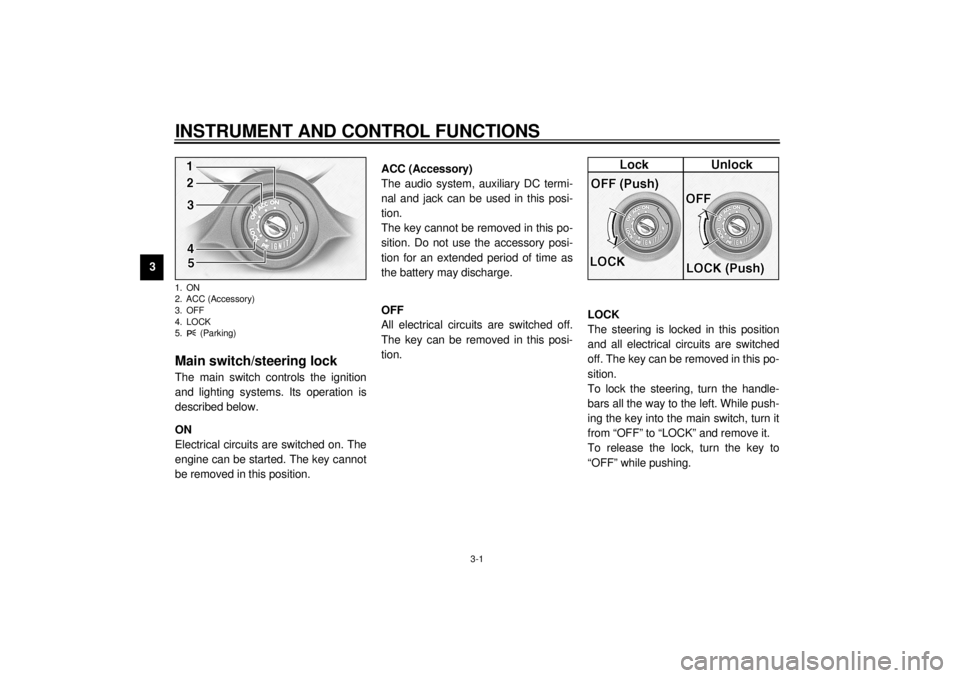
Main switch/steering lockThe main switch controls the ignition
and lighting systems. Its operation is
described below.
EAU00036
ON
Electrical circuits are switched on. The
engine can be started. The key cannot
be removed in this position.
EAU01842
ACC (Accessory)
The audio system, auxiliary DC termi-
nal and jack can be used in this posi-
tion.
The key cannot be removed in this po-
sition. Do not use the accessory posi-
tion for an extended period of time as
the battery may discharge.
EAU00038
OFF
All electrical circuits are switched off.
The key can be removed in this posi-
tion.
EAU00040*
LOCK
The steering is locked in this position
and all electrical circuits are switched
off. The key can be removed in this po-
sition.
To lock the steering, turn the handle-
bars all the way to the left. While push-
ing the key into the main switch, turn it
from “OFF” to “LOCK” and remove it.
To release the lock, turn the key to
“OFF” while pushing.
1. ON
2. ACC (Accessory)
3. OFF
4. LOCK
5. (Parking)E_5jc_Functions.fm Page 1 Saturday, October 16, 1999 1:08 PM
Page 16 of 121
INSTRUMENT AND CONTROL FUNCTIONS
3-2
3
EW000016
WARNING
@ Never turn the key to “OFF” or
“LOCK” when the motorcycle is
moving. The electrical circuits will
be switched off which may result in
loss of control or an accident. Be
sure the motorcycle is stopped be-
fore turning the key to “OFF” or
“LOCK”. @
On the right side of the headpipe, there
is also a place to lock the steering with
a padlock. Turn the handlebars to align
the holes in the two brackets and lock
the steering with a suitable padlock.
EAU01861
(Parking)
The steering is locked in this position,
and the taillight, license light and auxil-
iary light come on but all other circuits
are off. The key can be removed in this
position.
To use the parking position, first lock
the steering, then turn the key to “ ”.
Do not use this position for an extend-
ed length of time as the battery may
discharge.
1. Push
2. Turn
E_5jc_Functions.fm Page 2 Saturday, October 16, 1999 1:08 PM
Page 17 of 121
INSTRUMENT AND CONTROL FUNCTIONS
3-3
3
EAU00056
Indicator lights
EAU00058
1. Turn indicator lights “ ” / “ ”
The corresponding indicator flashes
when the turn switch is moved to the
left or right.
EAU00063
2. High beam indicator light “ ”
This indicator comes on when the
headlight high beam is used.
EAU01209
3. Oil level indicator light “ ”
This indicator light will come on if the oil
level is low. To check that the indicator
light is working properly:
l
Turn the engine stop switch to
“ ” and the main switch to “ON”.
l
Put the transmission in neutral or
apply the clutch lever.
l
Push the start switch.
If the indicator light does not come on
while pushing the start switch, have a
Yamaha dealer inspect the electrical
circuit.
NOTE:@ Even if the oil is filled to the specified
level, the indicator light may flicker
when riding on a slope or during sud-
den acceleration or deceleration, but
this is normal. @
E_5jc_Functions.fm Page 3 Saturday, October 16, 1999 1:08 PM
Page 18 of 121

INSTRUMENT AND CONTROL FUNCTIONS
3-4
3
EAU01774
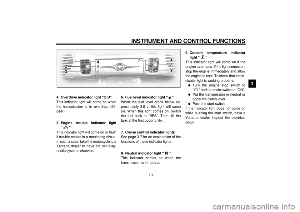
4. Overdrive indicator light “O/D”
This indicator light will come on when
the transmission is in overdrive (5th
gear).
EAU00091
5. Engine trouble indicator light
“”
This indicator light will come on or flash
if trouble occurs in a monitoring circuit.
In such a case, take the motorcycle to a
Yamaha dealer to have the self-diag-
nostic systems checked.
EAU00079
6. Fuel level indicator light “ ”
When the fuel level drops below ap-
proximately 3.5 L, this light will come
on. When this light comes on, switch
the fuel cock to “RES”. Then, fill the
tank at the first opportunity.
EAU01773
7. Cruise control indicator lights
See page 3-7 for an explanation of the
functions of these indicator lights.
EAU00061
8. Neutral indicator light “ ”
This indicator comes on when the
transmission is in neutral.
EAU01257*
9. Coolant temperature indicator
light “ ”
This indicator light will come on if the
engine overheats. If the light comes on,
stop the engine immediately and allow
the engine to cool. To check that the in-
dicator light is working properly:l
Turn the engine stop switch to
“ ” and the main switch to “ON”.
l
Put the transmission in neutral or
apply the clutch lever.
l
Push the start switch.
If the indicator light does not come on
while pushing the start switch, have a
Yamaha dealer inspect the electrical
circuit.
E_5jc_Functions.fm Page 4 Saturday, October 16, 1999 1:08 PM
Page 19 of 121

INSTRUMENT AND CONTROL FUNCTIONS
3-5
3
EAU01775*
SpeedometerThis speedometer is equipped with:l
an odometer
l
two trip odometers
l
a fuel reserve trip meter
l
a clockOdometer and trip meter modes
Use the trip meters to estimate how far
you can ride on a tank of fuel.
Use the fuel reserve trip meter to see
the distance traveled from when the
fuel level dropped to the reserve level.
Selecting a mode
Push the “SELECT” button to change
between the odometer mode “ODO”
and the trip odometer modes “TRIP 1”
and “TRIP 2” in the following order:
“ODO”
® “TRIP 1”
® “TRIP 2”
®
“ODO”
If the fuel level indicator light comes on
(see page 3-4), the odometer display
will automatically change to the fuel re-
serve trip meter mode “TRIP F” and
start counting the distance traveled
from that point. Push the “SELECT”
button to change between the fuel re-
serve trip meter, trip odometers and
odometer modes in the following order:
“TRIP F”
® “TRIP 1”
® “TRIP 2”
®
“ODO”
® “TRIP F”Resetting a meter
To reset a trip odometer to 0.0, select it
by pushing the “SELECT” button and
push the “RESET” button. To reset the
fuel reserve trip meter, select it by
pushing the “SELECT” button and
push the “RESET” button. The display
will return to “TRIP 1”. If you do not re-
set the fuel reserve trip meter manual-
ly, it will automatically reset and return
to “TRIP 1” after refueling and traveling
5 km.NOTE:@ After resetting the fuel reserve trip
meter, the display always returns to the
“TRIP 1” mode, unless a different mode
had been previously selected; in that
case, the display automatically returns
to the prior mode. @
1. Speedometer
2. Odometer/tripmeter/clock
3. “RESET” button
4. “SELECT” buttonE_5jc_Functions.fm Page 5 Saturday, October 16, 1999 1:08 PM