Page 64 of 104
6-19
PERIODIC MAINTENANCE AND MINOR REPAIR
1
2
3
4
5
6
7
8
9
EAU00687Wheels
To ensure maximum performance,
long service, and safe operation, note
the following:
8Always inspect the wheels
before a ride. Check for cracks,
bends, or warpage of the wheels.
If any abnormal condition exists
in a wheel, consult a Yamaha
dealer. Do not attempt even
small repairs to the wheel. If a
wheel is deformed or cracked, it
must be replaced.
8Tires and wheels should be bal-
anced whenever either one is
changed or replaced. Failure to
have a wheel balanced can
result in poor performance,
adverse handling characteristics,
and shortened tire life.
8Ride at moderate speeds after
changing a tire since the tire sur-
face must first be broken in for it
to develop its optimal character-
istics.
a
b12 3
EAU00694
Clutch lever free play
adjustment
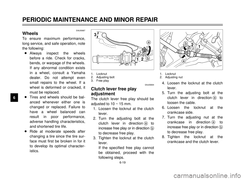
The clutch lever free play should be
adjusted to 10 ~ 15 mm.
1. Loosen the locknut at the clutch
lever.
2. Turn the adjusting bolt at the
clutch lever in directionato
increase free play or in direction b
to decrease free play.
3. Tighten the locknut at the clutch
lever.
If the specified free play cannot
be obtained, proceed with the
following steps.
1. Locknut
2. Adjusting bolt
3. Free play
b
a
12
4. Loosen the locknut at the clutch
lever.
5. Turn the adjusting bolt at the
clutch lever in directionato
loosen the cable.
6. Loosen the locknut at the
crankcase side.
7. Turn the adjusting nut at the
crankcase in directionato
increase free play or in direction b
to decrease free play.
8. Tighten the locknut at the
crankcase and the clutch lever.
1. Locknut
2. Adjusting nut
5AE-9-E3 (ENG) 4/11/0 11:06 AM Page 62
Page 65 of 104
6-20
PERIODIC MAINTENANCE AND MINOR REPAIR
1
2
3
4
5
6
7
8
9
1
2
b
a3
EAU00696
Front brake lever free play
adjustment
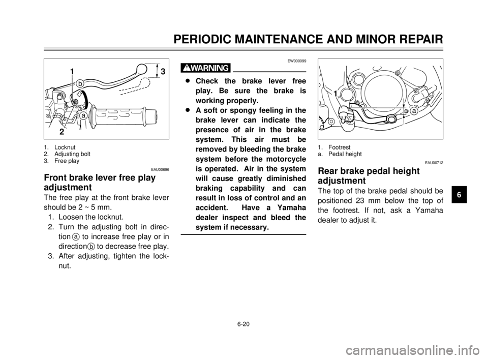
The free play at the front brake lever
should be 2 ~ 5 mm.
1. Loosen the locknut.
2. Turn the adjusting bolt in direc-
tionato increase free play or in
directionbto decrease free play.
3. After adjusting, tighten the lock-
nut.
1. Locknut
2. Adjusting bolt
3. Free play
EW000099
w
8 8
Check the brake lever free
play. Be sure the brake is
working properly.
8 8
A soft or spongy feeling in the
brake lever can indicate the
presence of air in the brake
system. This air must be
removed by bleeding the brake
system before the motorcycle
is operated. Air in the system
will cause greatly diminished
braking capability and can
result in loss of control and an
accident. Have a Yamaha
dealer inspect and bleed the
system if necessary.
a
1
EAU00712
Rear brake pedal height
adjustment
The top of the brake pedal should be
positioned 23 mm below the top of
the footrest. If not, ask a Yamaha
dealer to adjust it.
1. Footrest
a. Pedal height
5AE-9-E3 (ENG) 4/11/0 11:06 AM Page 63
Page 68 of 104
6-23
PERIODIC MAINTENANCE AND MINOR REPAIR
1
2
3
4
5
6
7
8
98Refill with the same type of brake
fluid. Mixing fluids may result in a
harmful chemical reaction and
lead to poor brake performance.
8Be careful that water does not
enter the master cylinder when
refilling. Water will significantly
lower the boiling point of the fluid
and may result in vapor lock.
8Brake fluid may deteriorate paint-
ed surfaces or plastic parts.
Always clean up spilled fluid
immediately.
8Have a Yamaha dealer check
the cause if the brake fluid level
goes down.
EAU00742Brake fluid replacement
The brake fluid should be replaced
only by trained Yamaha service per-
sonnel. Have the Yamaha dealer
replace the following components
during periodic maintenance or when
they are damaged or leaking:
8oil seals (every two years)
8brake hoses (every four years)
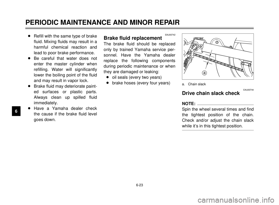
EAU00744Drive chain slack check
NOTE:
Spin the wheel several times and find
the tightest position of the chain.
Check and/or adjust the chain slack
while it’s in this tightest position.
a
a. Chain slack
5AE-9-E3 (ENG) 4/11/0 11:06 AM Page 66
Page 69 of 104
6-24
PERIODIC MAINTENANCE AND MINOR REPAIR
1
2
3
4
5
6
7
8
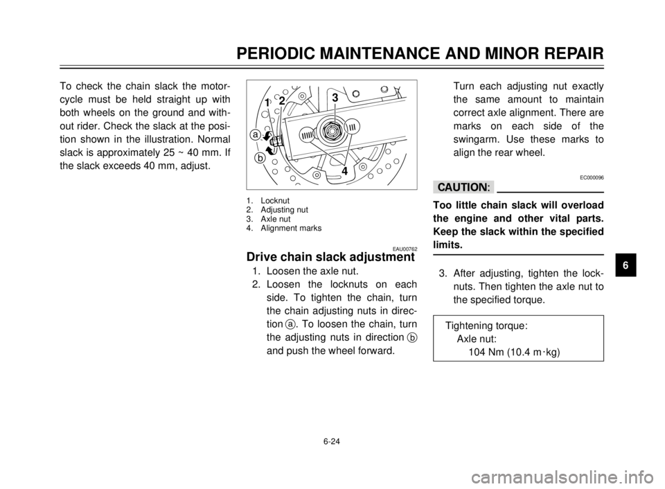
9 To check the chain slack the motor-
cycle must be held straight up with
both wheels on the ground and with-
out rider. Check the slack at the posi-
tion shown in the illustration. Normal
slack is approximately 25 ~ 40 mm. If
the slack exceeds 40 mm, adjust.
EAU00762Drive chain slack adjustment
1. Loosen the axle nut.
2. Loosen the locknuts on each
side. To tighten the chain, turn
the chain adjusting nuts in direc-
tiona. To loosen the chain, turn
the adjusting nuts in directionb
and push the wheel forward.
3
412
a
b
1. Locknut
2. Adjusting nut
3. Axle nut
4. Alignment marks
Turn each adjusting nut exactly
the same amount to maintain
correct axle alignment. There are
marks on each side of the
swingarm. Use these marks to
align the rear wheel.
EC000096
cC
Too little chain slack will overload
the engine and other vital parts.
Keep the slack within the specified
limits.
3. After adjusting, tighten the lock-
nuts. Then tighten the axle nut to
the specified torque.
Tightening torque:
Axle nut:
104 Nm (10.4 m0kg)
5AE-9-E3 (ENG) 4/11/0 11:06 AM Page 67
Page 77 of 104
6-32
PERIODIC MAINTENANCE AND MINOR REPAIR
1
2
3
4
5
6
7
8
9
12
EAU01078
Taillight bulb replacement
1. Remove the seat.
2. Remove panel A. (See page
6-7 for panel removal and instal-
lation procedures.)
3. To remove the socket, turn it
counterclockwise.
1. Screw (´2)
2. Panel A
1
4. To remove the defective bulb,
turn it counterclockwise.
5. Push a new bulb into the socket
and turn it clockwise.
6. Install the socket and turn it
clockwise.
7. Install the panel and the seat.
1. Socket
12
EAU01095
Turn signal light bulb
replacement
1. Remove the screw and the lens.
2. Remove the defective bulb by
pushing it inward and turning it
counterclockwise.
1. Lens
2. Screw
5AE-9-E3 (ENG) 4/11/0 11:06 AM Page 75
Page 78 of 104
6-33
PERIODIC MAINTENANCE AND MINOR REPAIR
1
2
3
4
5
6
7
8
9
1
1. Speedometer cable
EAU00894Front wheel removalEW000122
w
8 8
It is advisable to have a
Yamaha dealer service the
wheel.
8 8
Securely support the motorcy-
cle so there is no danger of it
falling over.
1. Remove the speedometer cable
from the front wheel side.
2
1
1. Pinch bolt
2. Wheel axle
2. Loosen the pinch bolt and wheel
axle.
3. Elevate the front wheel by plac-
ing a suitable stand under the
engine.
4. Remove the wheel axle and the
front wheel.
NOTE:
Do not depress the brake lever when
the disc and caliper are separated.
1
1. Bulb
3. Install a new bulb by pushing it
inward and turning it clockwise.
4. Install the lens and tighten the
screw.
5AE-9-E3 (ENG) 4/11/0 11:06 AM Page 76
Page 79 of 104
6-34
PERIODIC MAINTENANCE AND MINOR REPAIR
1
2
3
4
5
6
7
8
9
3. Install the wheel axle and let the
motorcycle down.
4. Push down hard on the handle-
bars several times to check for
proper fork operation.
5. Tighten the wheel axle to the
specified torque.
6. Install the pinch bolt and tighten
it to the specified torque.
7. Install the speedometer cable.Tightening torque:
Wheel axle:
59 Nm (5.9 m0kg)
Pinch bolt:
20 Nm (2.0 m0kg)
312
EAU01618Rear wheel removalEW000122
w
8 8
It is advisable to have a
Yamaha dealer service the
wheel.
8 8
Securely support the motorcy-
cle so there is no danger of it
falling over.
1. Loosen the axle nut.
1. Locknut
2. Adjusting nut
3. Axle nut
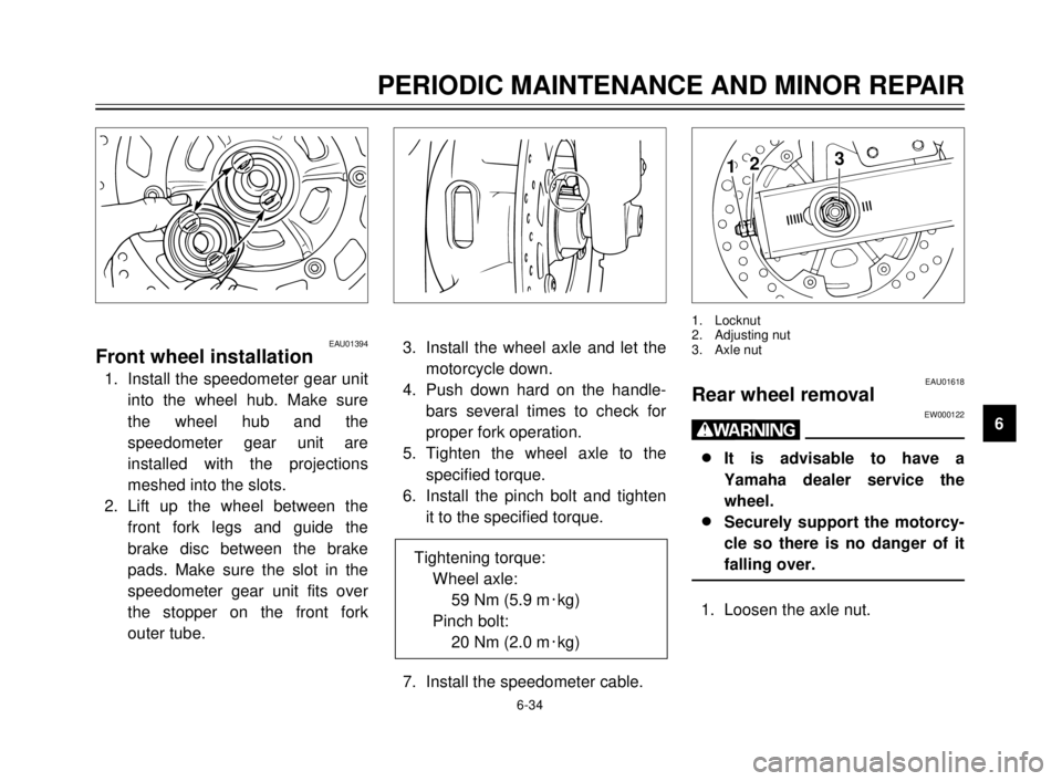
EAU01394Front wheel installation
1. Install the speedometer gear unit
into the wheel hub. Make sure
the wheel hub and the
speedometer gear unit are
installed with the projections
meshed into the slots.
2. Lift up the wheel between the
front fork legs and guide the
brake disc between the brake
pads. Make sure the slot in the
speedometer gear unit fits over
the stopper on the front fork
outer tube.
5AE-9-E3 (ENG) 4/11/0 11:06 AM Page 77
Page 80 of 104
6-35
PERIODIC MAINTENANCE AND MINOR REPAIR
1
2
3
4
5
6
7
8
9
2. Elevate the rear wheel by placing
a suitable stand under the
engine.
3. Remove the axle nut.
4. Loosen the locknuts and chain
adjusting nuts on each side.
5. Push the wheel forward and
remove the drive chain.
6. While supporting the brake
caliper, pull out the wheel axle.
7. Remove the wheel assembly.
NOTE:
8Do not depress the brake pedal
when the disc and caliper are
separated.
8You do not have to disassemble
the chain in order to remove or
install the rear wheel.
EAU01620
Rear wheel installation
1. Install the rear brake caliper.
Make sure the slot in the caliper
bracket is fit over the stopper on
the swingarm.
2. Install the rear wheel and chain.
Guide the brake disc between
the brake pads. Make sure there
is enough gap between the
brake pads before inserting the
brake disc.
3. Install the wheel axle and axle
nut, and let the motorcycle down.
5AE-9-E3 (ENG) 4/11/0 11:06 AM Page 78