Page 14 of 104
1
2
3
4
5
6
7
8
9
DESCRIPTION
2-3
15. Clutch lever (page 3-8, 6-20)
16. Left handlebar switches (page 3-5)
17. Speedometer (page 3-4)
18. Engine temperature gauge (page 3-5)
19. Tachometer (page 3-5)20. Right handlebar switches (page 3-6)
21. Front brake lever (page 3-9, 6-21)
22. Throttle grip (page 6-17)
23. Fuel tank cap (page 3-9)
24. Main switch/Steering lock (page 3-1)
15 16 17 18 19 20 21
22 23 24
Controls/Instruments
5AE-9-E3 (ENG) 4/11/0 11:06 AM Page 12
Page 15 of 104

INSTRUMENT AND CONTROL FUNCTIONS
Main switch/steering lock........................................3-1
Indicator lights ........................................................3-2
Oil level indicator circuit check ...............................3-3
Speedometer ..........................................................3-4
Tachometer ............................................................3-4
Engine temperature gauge .....................................3-5
Handlebar switches ................................................3-5
Headlight beam variation ........................................3-6
Clutch lever.............................................................3-8
Shift pedal...............................................................3-8
Front brake lever ....................................................3-8
Rear brake pedal ....................................................3-9
Fuel tank cap ..........................................................3-9
Fuel.......................................................................3-10
Catalyzer (for Switzerland and Austria) ................3-11
Two-stroke engine oil ...........................................3-12
Fuel cock ..............................................................3-12
Starter (choke) “1” ..............................................3-13
Seat ......................................................................3-13
Helmet holder .......................................................3-14
Rear shock absorber adjustment..........................3-14
Note on handling of the Yamaha Energy
Induction System (Y.E.I.S.) ..................................3-15Y.P.V.S. (Yamaha Power Valve System) .............3-16
Sidestand..............................................................3-16
Sidestand/clutch switch operation check ..............3-17
3
5AE-9-E3 (ENG) 4/11/0 11:06 AM Page 13
Page 24 of 104
3-9
INSTRUMENT AND CONTROL FUNCTIONS
1
2
3
4
5
6
7
8
91
1. Rear brake pedal
EAU00162Rear brake pedal
The rear brake pedal is on the right
side of the motorcycle. Press down
on the brake pedal to apply the rear
brake.
NOTE:
This tank cap cannot be closed
unless the key is in the lock. The key
cannot be removed if the cap is not
locked properly.
EW000023
w
Be sure the cap is properly
installed and locked in place
before riding the motorcycle.
2
1
EAU02935
Fuel tank cap
To open
Open the lock cover. Insert the key
and turn it 1/4 turn clockwise. The
lock will be released and the cap can
be opened.
To close
Push the tank cap into position with
the key inserted. To remove the key,
turn it counterclockwise to the original
position. Then, close the lock cover.
1. Open
2. Unlock
5AE-9-E3 (ENG) 4/11/0 11:06 AM Page 22
Page 26 of 104

3-11
INSTRUMENT AND CONTROL FUNCTIONS
1
2
3
4
5
6
7
8
9
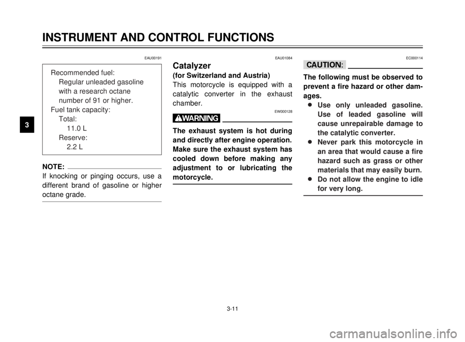
EAU00191
NOTE:
If knocking or pinging occurs, use a
different brand of gasoline or higher
octane grade.
EAU01084
Catalyzer
(for Switzerland and Austria)
This motorcycle is equipped with a
catalytic converter in the exhaust
chamber.
EW000128
w
The exhaust system is hot during
and directly after engine operation.
Make sure the exhaust system has
cooled down before making any
adjustment to or lubricating the
motorcycle.
EC000114
cC
The following must be observed to
prevent a fire hazard or other dam-
ages.
8 8
Use only unleaded gasoline.
Use of leaded gasoline will
cause unrepairable damage to
the catalytic converter.
8 8
Never park this motorcycle in
an area that would cause a fire
hazard such as grass or other
materials that may easily burn.
8 8
Do not allow the engine to idle
for very long.Recommended fuel:
Regular unleaded gasoline
with a research octane
number of 91 or higher.
Fuel tank capacity:
Total:
11.0 L
Reserve:
2.2 L
5AE-9-E3 (ENG) 4/11/0 11:06 AM Page 24
Page 27 of 104
3-12
INSTRUMENT AND CONTROL FUNCTIONS
1
2
3
4
5
6
7
8
9ON1
1. Arrow mark pointing to “ON”
EAU03050
Fuel cock
The fuel cock supplies fuel from the
tank to the carburetor while filtering it
also.
The fuel cock has three positions:
OFF
With the lever in this position, fuel will
not flow. Always return the lever to
this position when the engine is not
running.ON
With the lever in this position, fuel
flows to the carburetor. Normal riding
is done with the lever in this position.
1
OFF
1. Arrow mark pointing to “OFF”
EAU02956
Two-stroke engine oil
Make sure the two-stroke engine oil
is at the specified level. Fill with oil as
necessary.
1
1. Filler cap
Recommended oil:
Yamalube 2 or 2-stroke
engine oil (JASO FC grade or
ISO EG-C, EG-D grade)
Oil quantity:
1.2 L
OFF: closed positionON: normal position
5AE-9-E3 (ENG) 4/11/0 11:06 AM Page 25
Page 58 of 104

6-13
PERIODIC MAINTENANCE AND MINOR REPAIR
1
2
3
4
5
6
7
8
9
2
1
4
5
3
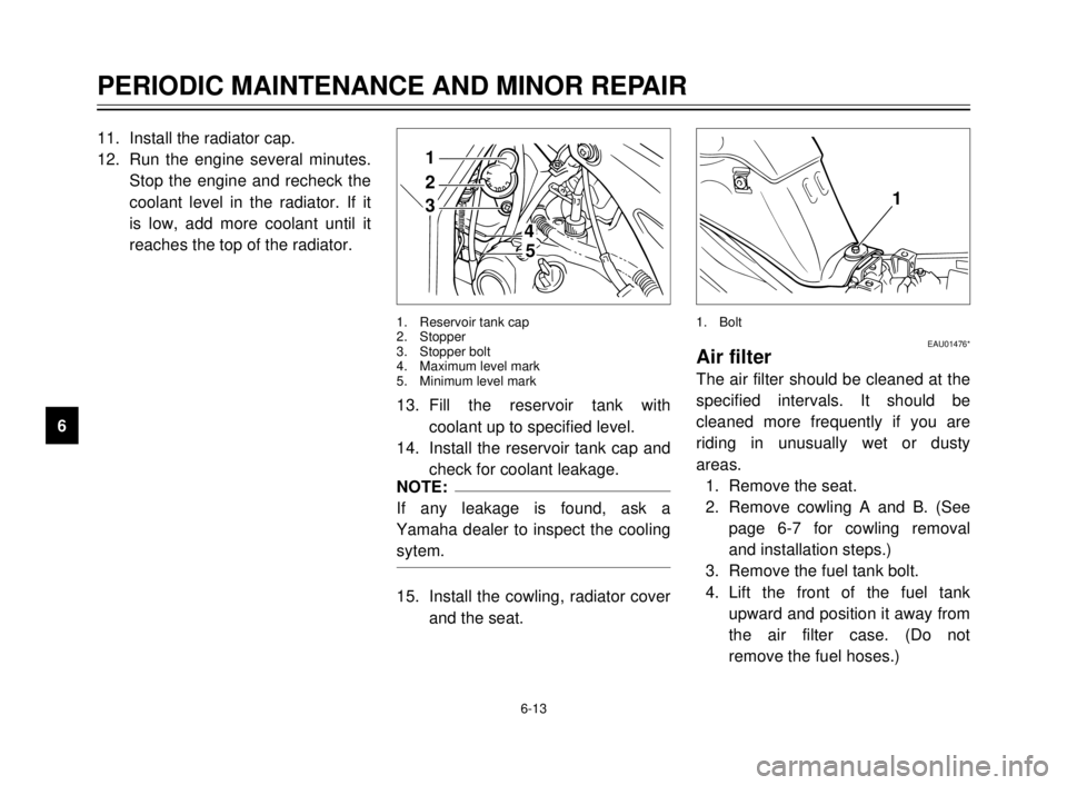
1. Reservoir tank cap
2. Stopper
3. Stopper bolt
4. Maximum level mark
5. Minimum level mark
11. Install the radiator cap.
12. Run the engine several minutes.
Stop the engine and recheck the
coolant level in the radiator. If it
is low, add more coolant until it
reaches the top of the radiator.
13. Fill the reservoir tank with
coolant up to specified level.
14. Install the reservoir tank cap and
check for coolant leakage.
NOTE:
If any leakage is found, ask a
Yamaha dealer to inspect the cooling
sytem.
15. Install the cowling, radiator cover
and the seat.
1
EAU01476*Air filter
The air filter should be cleaned at the
specified intervals. It should be
cleaned more frequently if you are
riding in unusually wet or dusty
areas.
1. Remove the seat.
2. Remove cowling A and B. (See
page 6-7 for cowling removal
and installation steps.)
3. Remove the fuel tank bolt.
4. Lift the front of the fuel tank
upward and position it away from
the air filter case. (Do not
remove the fuel hoses.)
1. Bolt
5AE-9-E3 (ENG) 4/11/0 11:06 AM Page 56
Page 89 of 104

1
2
3
4
5
6
7
8
9
7-4
Storage
Short-term
Always store your motorcycle in a
cool, dry place and, if necessary, pro-
tect it against dust with a porous
cover.
ECA00014
cC
8
8
Storing the motorcycle in a
poorly ventilated room or cov-
ering it with a tarp while it is
still wet will allow water and
humidity to seep in and cause
rust.
8 8
To prevent corrosion, avoid
damp cellars, stables (because
of the presence of ammonia)
and areas where strong chemi-
cals are stored.
Long-term
Before storing your motorcycle for
several months:
1. Follow all the instructions in the
“Care” section of this chapter.
2. Drain the carburetor float cham-
ber by loosening the drain bolt;
this will prevent fuel deposits
from building up. Pour the
drained fuel into the fuel tank.
3. Only for motorcycles equipped
with a fuel cock which has an
“OFF” position: Turn the fuel
cock to “OFF”.
4. Fill up the fuel tank and add fuel
stabilizer (if available) to prevent
the fuel tank from rusting and the
fuel from deteriorating.
5. Perform the following steps to
protect the cylinder, piston rings,
etc. from corrosion.a. Remove the spark plug cap and
spark plug.
b. Pour a teaspoonful of engine oil
into the spark plug bore.
c. Install the spark plug cap onto
the spark plug and place the
spark plug on the cylinder head
so that the electrodes are
grounded. (This will limit spark-
ing during the next step.)
d. Turn the engine over several
times with the starter. (This will
coat the cylinder wall with oil.)
e. Remove the spark plug cap from
the spark plug, install the spark
plug and then the spark plug
cap.
EWA00003
w
When turning the engine over, be
sure to ground the spark plug elec-
trodes to prevent damage or injury
from sparking.
MOTORCYCLE CARE AND STORAGE
7
5AE-9-E3 (ENG) 4/11/0 11:06 AM Page 87
Page 92 of 104

SPECIFICATIONS
1
2
3
4
5
6
7
8
9
Specifications
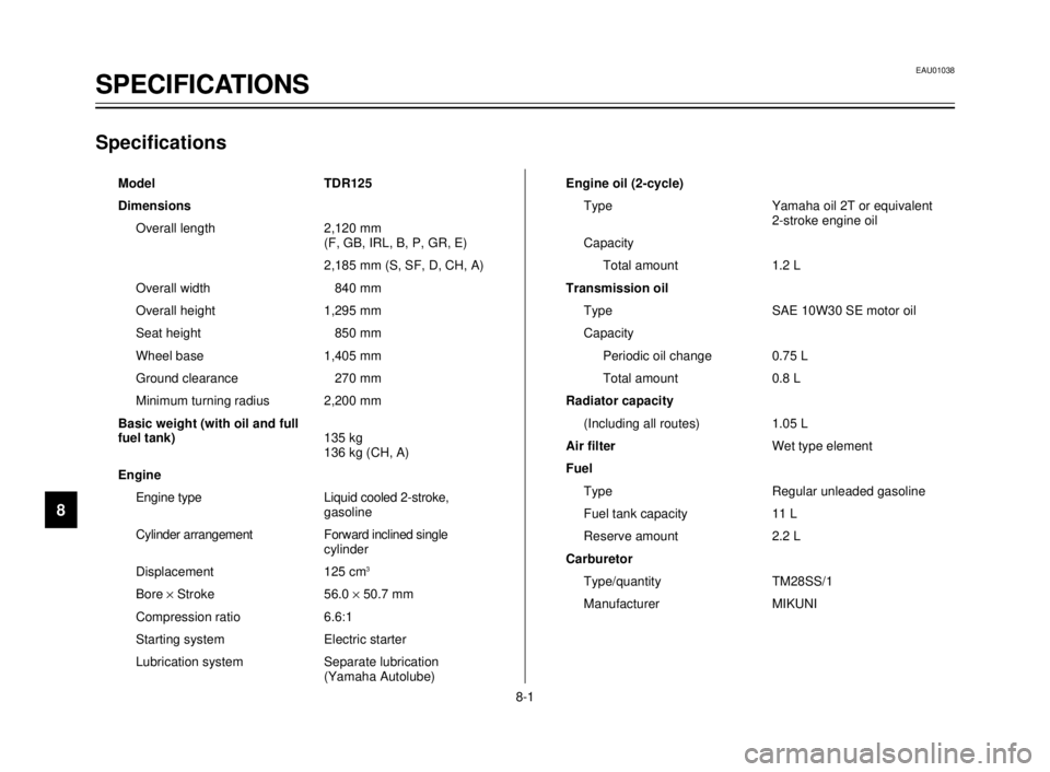
Model TDR125
Dimensions
Overall length 2,120 mm
(F, GB, IRL, B, P, GR, E)
2,185 mm (S, SF, D, CH, A)
Overall width 840 mm
Overall height 1,295 mm
Seat height 850 mm
Wheel base 1,405 mm
Ground clearance 270 mm
Minimum turning radius 2,200 mm
Basic weight (with oil and full
fuel tank)135 kg
136 kg (CH, A)
Engine
Engine type Liquid cooled 2-stroke,
gasoline
Cylinder arrangement Forward inclined single
cylinder
Displacement 125 cm
3
Bore ´Stroke 56.0 ´50.7 mm
Compression ratio 6.6:1
Starting system Electric starter
Lubrication system Separate lubrication
(Yamaha Autolube)Engine oil (2-cycle)
Type Yamaha oil 2T or equivalent
2-stroke engine oil
Capacity
Total amount 1.2 L
Transmission oil
Type SAE 10W30 SE motor oil
Capacity
Periodic oil change 0.75 L
Total amount 0.8 L
Radiator capacity
(Including all routes) 1.05 L
Air filterWet type element
Fuel
Type Regular unleaded gasoline
Fuel tank capacity 11 L
Reserve amount 2.2 L
Carburetor
Type/quantity TM28SS/1
Manufacturer MIKUNI
EAU01038
SPECIFICATIONS
8-1
5AE-9-E3 (ENG) 4/11/0 11:06 AM Page 90