Page 1997 of 4770
BO0LN±01
N20998
H01772
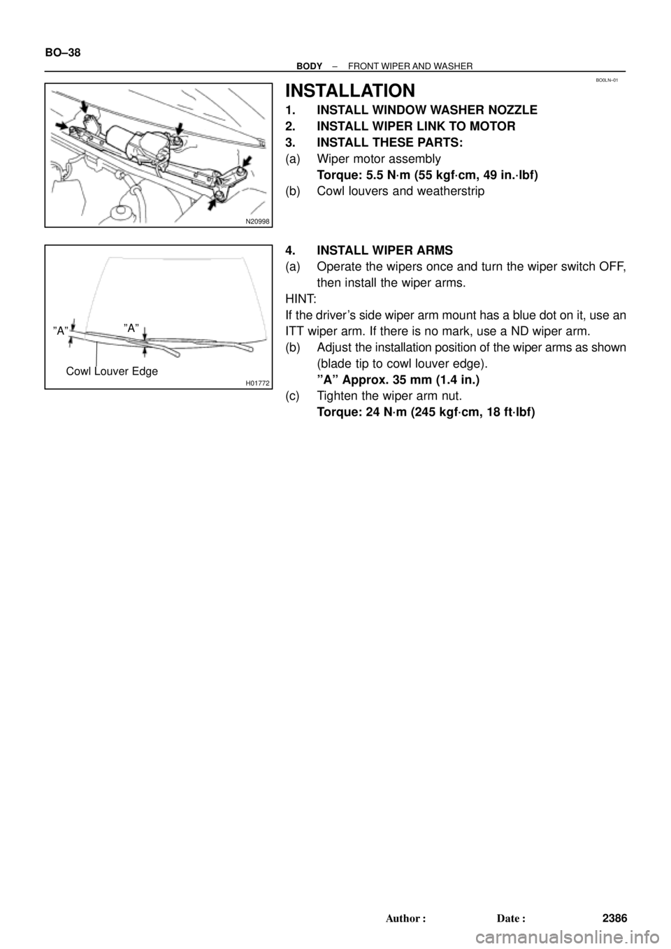
ºAººAº
Cowl Louver Edge
BO±38
± BODYFRONT WIPER AND WASHER
2386 Author�: Date�:
INSTALLATION
1. INSTALL WINDOW WASHER NOZZLE
2. INSTALL WIPER LINK TO MOTOR
3. INSTALL THESE PARTS:
(a) Wiper motor assembly
Torque: 5.5 N´m (55 kgf´cm, 49 in.´lbf)
(b) Cowl louvers and weatherstrip
4. INSTALL WIPER ARMS
(a) Operate the wipers once and turn the wiper switch OFF,
then install the wiper arms.
HINT:
If the driver's side wiper arm mount has a blue dot on it, use an
ITT wiper arm. If there is no mark, use a ND wiper arm.
(b) Adjust the installation position of the wiper arms as shown
(blade tip to cowl louver edge).
ºAº Approx. 35 mm (1.4 in.)
(c) Tighten the wiper arm nut.
Torque: 24 N´m (245 kgf´cm, 18 ft´lbf)
Page 2296 of 4770

Z18811
Maintenance±Free Battery
Type A
Type B
Blue White Red
OK Charging
NecessaryInsufficient
Water
GREEN EYE DARK EYECLEAR EYE or
CHARGED DISCHARGED ADD WATERLIGHT YELLOW
Z00015
Z00038
DENSOBorroughs
CH0086
CORRECTWRONG CH±2
± CHARGING (5S±FE)CHARGING SYSTEM
1749 Author�: Date�:
HINT:
Check the indicator as shown in the illustration.
4. CHECK BATTERY TERMINALS, FUSIBLE LINK AND
FUSES
(a) Check that the battery terminals are not loose or cor-
roded.
If the terminals are corroded, clean the terminals.
(b) Check the fusible link, H±fuses, M±fuse and fuses for
continuity.
5. INSPECT DRIVE BELTS
(a) Visually check the drive belt for excessive wear, frayed
cords etc.
If any defect has been found, replace the drive belt.
HINT:
Cracks on the rib side of a drive belt are considered acceptable.
If the drive belt has chunks missing from the ribs, it should be
replaced.
(b) Using a belt tension gauge, measure the belt tension.
Belt tension gauge:
DENSO BTG±20 (95506±00020)
Borroughs No. BT±33±73F
Drive belt tension:
w/ A/C New belt
Used belt165 ± 25 lbf
110 ± 10 lbf
w/o A/C New belt
Used belt125 ± 25 lbf
95 ± 20 lbf
If the belt tension is not as specified, adjust it.
HINT:
�ºNew beltº refers to a belt which has been used less than
5 minutes on a running engine.
�ºUsed beltº refers to a belt which has been used on a run-
ning engine for 5 minutes or more.
�After installing a belt, check that it fits properly in the
ribbed grooves.
�Check with your hand to confirm that the belt has not
slipped out of the groove on the bottom of the pulley.
Page 2312 of 4770

Z18811
Maintenance±Free Battery
Type A
Type B
Blue White Red
OK Charging
NecessaryInsufficient
Water
GREEN EYE DARK EYECLEAR EYE or
CHARGED DISCHARGED ADD WATERLIGHT YELLOW
Z00015
Z00038
DENSO
Borroughs
CH0086
CORRECT WRONG CH±2
± CHARGING (1MZ±FE)CHARGING SYSTEM
1765 Author�: Date�:
HINT:
Check the indicator as shown in the illustration.
4. CHECK BATTERY TERMINALS, FUSIBLE LINK AND
FUSES
(a) Check that the battery terminals are not loose or cor-
roded.
If the terminals are corroded, clean the terminals.
(b) Check the fusible link, H±fuses, M±fuse and fuses for
continuity.
5. INSPECT DRIVE BELTS
(a) Visually check the drive belt for excessive wear, frayed
cords etc.
If any defect has been found, replace the drive belt.
HINT:
Cracks on the rib side of a drive belt are considered acceptable.
If the drive belt has chunks missing from the ribs, it should be
replaced.
(b) Using a belt tension gauge, measure the belt tension.
Belt tension gauge:
DENSO BTG±20 (95506±00020)
Borroughs No. BT±33±73F
Drive belt tension:
New belt175 ± 5 lbf
Used belt115 ± 20 lbf
If the belt tension is not as specified, adjust it.
HINT:
�ºNew beltº refers to a belt which has been used less than
5 minutes on a running engine.
�ºUsed beltº refers to a belt which has been used on a run-
ning engine for 5 minutes or more.
�After installing a belt, check that it fits properly in the
ribbed grooves.
�Check with your hand to confirm that the belt has not
slipped out of the groove on the bottom of the pulley.
Page 3437 of 4770
CYLINDER HEAD
EM±45
1217 Author�: Date�:
(d) Check the valve overall length.
Standard overall length:")
EM2534
Overall Length
EM0255
P03272
45° Carbide
Cutter
Z00055
Width
± ENGINE MECHANICAL (5S±FE)CYLINDER HEAD
EM±45
1217 Author�: Date�:
(d) Check the valve overall length.
Standard overall length:
Intake97.40 ± 97.80 mm (3.8346 ± 3.8504 in.)
Exhaust98.25 ± 98.65 mm (3.8681 ± 3.8839 in.)
Minimum overall length:
Intake97.1 mm (3.823 in.)
Exhaust98.0 mm (3.858 in.)
If the overall length is less than minimum, replace the valve.
(e) Check the surface of the valve stem tip for wear.
If the valve stem tip is worn, resurface the tip with a grinder or
replace the valve.
NOTICE:
Do not grind off more than the minimum length.
8. INSPECT AND CLEAN VALVE SEATS
(a) Using a 45° carbide cutter, resurface the valve seats.
Remove only enough metal to clean the seats.
(b) Check the valve seating position.
Apply a light coat of prussian blue (or white lead) to the
valve face. Lightly press the valve against the seat. Do not
rotate valve.
(c) Check the valve face and seat for the following:
�If blue appears 360° around the face, the valve is
concentric. If not, replace the valve.
�If blue appears 360° around the valve seat, the
guide and face are concentric. If not, resurface the
seat.
�Check that the seat contact is in the middle of the
valve face with the following width:
1.0 ± 1.4 mm (0.039 ± 0.055 in.)
Page 3552 of 4770
CYLINDER HEAD
1332 Author�: Date�:
(d) Check the valve overall length.
Standard over")
EM2534
Overall Length
EM0255
P12704
P12729
Width
Z03988
45°
1.0 ± 1.4 mm30° EM±46
± ENGINE MECHANICAL (1MZ±FE)CYLINDER HEAD
1332 Author�: Date�:
(d) Check the valve overall length.
Standard overall length:
Intake95.45 mm (3.5779 in.)
Exhaust95.40 mm (3.7559 in.)
Minimum overall length:
Intake94.95 mm (3.7382 in.)
Exhaust94.90 mm (3.7362 in.)
If the overall length is less than minimum, replace the valve.
(e) Check the surface of the valve stem tip for wear.
If the valve stem tip is worn, resurface the tip with a grinder or
replace the valve.
NOTICE:
Do not grind off more than minimum.
11. INSPECT AND CLEAN VALVE SEATS
(a) Using a 45° carbide cutter, resurface the valve seats.
Remove only enough metal to clean the seats.
(b) Check the valve seating position.
Apply a light coat of prussian blue (or white lead) to the
valve face. Lightly press the valve against the seat. Do not
rotate valve.
(c) Check the valve face and seat for the following:
�If blue appears 360° around the face, the valve is
concentric. If not, replace the valve.
�If blue appears 360° around the valve seat, the
guide and face are concentric. If not, resurface the
seat.
�Check that the seat contact is in the middle of the
valve face with the following width:
1.0 ± 1.4 mm (0.039 ± 0.055 in.)
If not, correct the valve seats as follows:
(1) If the seating is too high on the valve face, use 30°
and 45° cutters to correct the seat.
Page 3700 of 4770

V08423 Knock Sensor 1
GRECM
KNK
E1 12
E6
WIRING DIAGRAM
Wiring Diagram
This shows a wiring diagram of the circuit.
Use this diagram together with ELECTRICAL
WIRING DIAGRAM to thoroughly understand the
circuit.
Wire colors are indicated by an alphabetical code.
B = Black, L = Blue, R = Red, BR = Brown,
LG = Light Green, V = Violet, G = Green,
O = Orange, W = White, GR = Gray, P = Pink,
Y = Yellow, SB = Sky Blue
The first letter indicates the basic wire color and
the second letter indicates the color of the stripe.
DTC P0325Knock Sensor 1 Circuit Malfunction
CIRCUIT DESCRIPTION
Knock sensor is fitted to the cylinder block to detect engine knocking. This sensor contains a piezoelectric element which
generates a voltage when it becomes deformed, which occurs when the cylinder block vibrates due to knocking. If engine
knocking occurs, ignition timing is retarded to suppress it.
DTC No. DTC Detecting Condition Trouble Area
P0325No knock sensor 1 signal to ECM with engine speed,
1,200 rpm or more.� Open or short in knock sensor1 circuit
� Knock sensor 1 (looseness)
� ECM
If the ECM detects the above diagnosis conditions, it operates the fall safe function in which the corrective retard angle
value is set to the maximum value.
� Diagnostic Trouble Code No. and Detection Item
� Circuit Description
The major role and operation, etc. of the circuit
and its component parts are explained.
� Indicates the diagnostic trouble code, diagnostic
trouble code set parameter and suspect area of
the problem.
�
± INTRODUCTIONHOW TO TROUBLESHOOT ECU CONTROLLED
SYSTEMSIN±29
29 Author�: Date�:
6. CIRCUIT INSPECTION
How to read and use each page is shown below.
Page 3958 of 4770
PP1XJ±01
± PREPARATIONAIR CONDITIONING
PP±107
159 Author�: Date�:
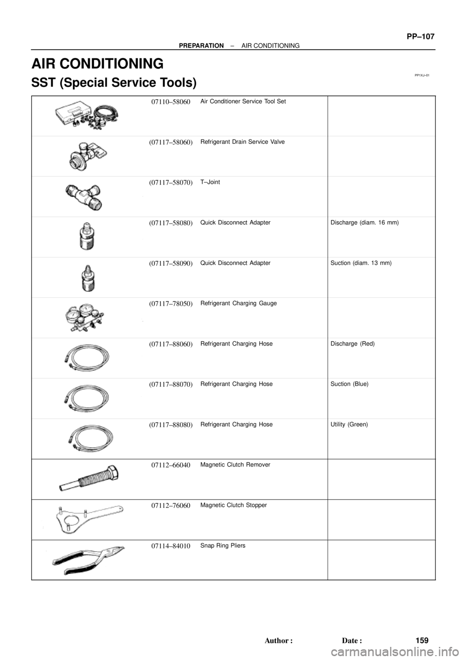
AIR CONDITIONING
SST (Special Service Tools)
07110±58060Air Conditioner Service Tool Set
(07117±58060)Refrigerant Drain Service Valve
(07117±58070)T±Joint
(07117±58080)Quick Disconnect AdapterDischarge (diam. 16 mm)
(07117±58090)Quick Disconnect AdapterSuction (diam. 13 mm)
(07117±78050)Refrigerant Charging Gauge
(07117±88060)Refrigerant Charging HoseDischarge (Red)
(07117±88070)Refrigerant Charging HoseSuction (Blue)
(07117±88080)Refrigerant Charging HoseUtility (Green)
07112±66040Magnetic Clutch Remover
07112±76060Magnetic Clutch Stopper
07114±84010Snap Ring Pliers
Page 4423 of 4770

Toyota Supports ASE CertificationPage 1 of 2
AX003±00Title:
PORT INSTALLED RS3000 TVIP TRUNK
COURTESY CONNECTION
Models:
'99 Camry
Technical Service
BULLETIN
March 31, 2000
The trunk courtesy connection for 1999 model year Camry vehicles equipped with a Port
Installed Option RS3000 (V3) has been relocated from the luggage compartment light
switch to below the dash (lower finish panel) on the driver's side in the Instrument Panel
J/B. (Refer to Illustrations A & B on page 2.)
�The location was changed to improve the installation process.
�A splicing connector is used for the new trunk courtesy wire installation (blue) to the
vehicle's wire harness at Instrument Panel J/B (red/yellow).
�The previous location is the same as the dealer installed RS3000 trunk courtesy
connection to the luggage compartment light switch connection.
For service related purposes, this bulletin describes the procedures to locate the new
trunk courtesy connection at Instrument Panel J/B in vehicles equipped with PIO
RS3000.
�The remote transmitter has two
buttons, Top and Bottom.�The status monitor has a Toyota label,
LED, and microphone.
Remote Control
LED
Status Monitor
Microphone
�1999 model year Camry vehicles equipped with PIO (V3) TVIP.
OP CODEDESCRIPTIONTIMEOPNT1T2
N/ANot Applicable to Warranty ±±±±
ACCESSORIES
Introduction
Applicable
Vehicles
Warranty
Information