Page 4198 of 4770
Width
± SUPPLEMENTAL RESTRAINT SYSTEMSTEERING WHEEL PAD AND SPIRAL CABLE
RS±23
2168 Author�: Date�:
(e) Install the SST.
CAUTION:
Pl")
H06696
SST
H00401Weight
x y
y
R04211
Inner Diam.
Tires
(3 or More)Width
± SUPPLEMENTAL RESTRAINT SYSTEMSTEERING WHEEL PAD AND SPIRAL CABLE
RS±23
2168 Author�: Date�:
(e) Install the SST.
CAUTION:
Place the disc wheel on the level ground.
(1) Connect the connector of SST to the steering wheel
pad connector.
SST 09082±00700
NOTICE:
To avoid damaging the SST connector and wire harness,
do not lock the secondary lock of the twin lock. Also, se-
cure some slack for the SST wire harness inside the disc
wheel.
(2) Move the SST to at least 10 m (33 ft) away from the
steering wheel pad tied down on the disc wheel.
(f) Cover the steering wheel pad with a cardboard box or
tires.
�Covering method using a cardboard box:
Cover the steering wheel pad with the cardboard
box and weight the cardboard box down in 4 places
with at least 190 N (20 kg, 44 lb).
Size of cardboard box:
Must exceed the following dimensions:
x= 460 mm (18.11 in.)
When dimension of the cardboard box exceeds the di-
ameter of the disc wheel with tire to which the steer-
ing wheel pad is tied
x= 460 mm (18.11 in.) + width of tire
y= 650 mm (25.59 in.)
NOTICE:
If a cardboard box smaller than the specified size is used,
the cardboard box will be broken by the shock from the air-
bag deployment.
�Covering method using tires:
Place at least 3 tires without disc wheel on top of the
disc wheel with tire to which the steering wheel pad
is tied.
Tire size: Must exceed the following dimensions±
Width: 185 mm (7.87 in.)
Inner diameter: 360 mm (14.17 in.)
Page 4209 of 4770

W03519
L
M
W03652
2 times or more
R08582
Width
Inner
Diam. RS±34
± SUPPLEMENTAL RESTRAINT SYSTEMFRONT PASSENGER AIRBAG ASSEMBLY
2179 Author�: Date�:
CAUTION:
If the front passenger airbag assembly is tied down with
too thin wire harness, it may snap. This is highly danger-
ous. Always use a wire harness which is at least 1.25 mm
2
(0.0019 in.2).
HINT:
To calculate the square of the stripped wire harness section:
Square = 3.14 X (Diameter)
2 divided by 4
(1) Install the 2 bolts with washers in the 2 bolt holes in
the front passenger airbag assembly,
Bolt:
L: 35.0 mm (1.387 in.)
M: 6.0 mm (0.236 in.)
Pitch: 1.0 mm (0.039 in.)
NOTICE:
�Tighten the bolts by hand until the bolts become diffi-
cult to turn.
�Do not tighten the bolts too much.
(2) Using 3 wire harness, wind the wire harness at least
2 times each around the bolts installed on the front
passenger airbag assembly.
(3) Position the front passenger airbag assembly in-
side the tire with the airbag deployment side facing
inside.
Tire size: Must exceed the following dimensions±
Width: 185 mm (7.28 in.)
Inner diameter: 360 mm (14.17 in.)
CAUTION:
�Make sure that the wire harness is tight. It is very dan-
gerous if looseness in the wire harness results in the
front passenger airbag assembly coming free due to
the shock from the airbag deploying.
�Always tie down the front passenger airbag assembly
with the airbag deployment side facing inside.
NOTICE:
The tire will be marked by the airbag deployment, so use a
redundant tire.
Page 4220 of 4770
H01333
H01334
H08326
Inner
Diam.Width
AB0158
SSTBattery
± SUPPLEMENTAL RESTRAINT SYSTEMSIDE AIRBAG ASSEMBLY (TMC Made)
RS±45
2190 Author�: Date�:
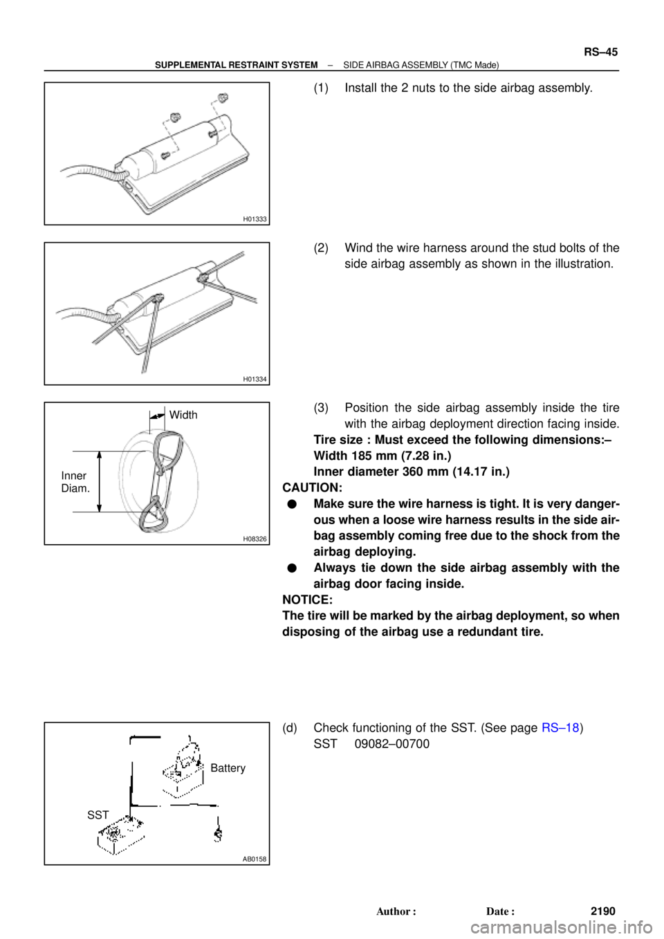
(1) Install the 2 nuts to the side airbag assembly.
(2) Wind the wire harness around the stud bolts of the
side airbag assembly as shown in the illustration.
(3) Position the side airbag assembly inside the tire
with the airbag deployment direction facing inside.
Tire size : Must exceed the following dimensions:±
Width 185 mm (7.28 in.)
Inner diameter 360 mm (14.17 in.)
CAUTION:
�Make sure the wire harness is tight. It is very danger-
ous when a loose wire harness results in the side air-
bag assembly coming free due to the shock from the
airbag deploying.
�Always tie down the side airbag assembly with the
airbag door facing inside.
NOTICE:
The tire will be marked by the airbag deployment, so when
disposing of the airbag use a redundant tire.
(d) Check functioning of the SST. (See page RS±18)
SST 09082±00700
Page 4342 of 4770
 Check the tires for wear and proper inflation pressu")
R03031
SA078±01
R15157
Front
R07928
SA±2
± SUSPENSION AND AXLETIRE AND WHEEL
1953 Author�: Date�:
TIRE AND WHEEL
INSPECTION
1. INSPECT TIRE
(a) Check the tires for wear and proper inflation pressure.
Cold inflation pressure:
Normal driving
Tire sizeFront, Rear
kPa (kgf/cm2 or bar, psi)
P195/70R14 90S, 90H210 (2.1, 30)
P205/65R15 92H*1 220 (2.2, 32)
*2 200 (2.0, 29)
*1: For all loads including full rated loads
*
2: For reduced loads (1 to 4 passengers)
Trailer towing
Tire sizeFront, Rear
kPa (kgf/cm2 or bar, psi)
P195/70R14 90S*1 210 (2.1, 30)
*2 240 (2.4, 36)
P205/65R15 92H*1 220 (2.2, 32)
*2 240 (2.4, 36)
*1: For driving under 160 km/h (100 mph)
*
2: For driving at 160 km/h (100 mph) or over
(b) Check the tire runout.
Tire runout: 1.0 mm (0.039 in.) or less
2. ROTATING TIRES
HINT:
See the illustration for where to rotate each tire.
3. INSPECT WHEEL BALANCE
(a) Check and adjust the Off±the±car balance.
(b) If necessary, check and adjust the On±the±car balance.
Imbalance after adjustment:
8.0 g (0.018 lb) or less
Page 4344 of 4770

W03085
Front
R03030
Rear
SA079±01
Z03382
SA3213
AB
C D
Front SA±4
± SUSPENSION AND AXLEFRONT WHEEL ALIGNMENT
1955 Author�: Date�:
FRONT WHEEL ALIGNMENT
INSPECTION
1. MEASURE VEHICLE HEIGHT
Tire sizeFront*1 mm (in.)Rear*2 mm (in.)
195/70R14212 (8.35)264 (10.39)
205/65R15215 (8.46)266 (10.49)
*1: Front measuring point
Measure from the ground to the center of the front side lower
suspension arm mounting bolt.
*
2: Rear measuring point
Measure from the ground to the center of the strut rod mounting
bolt.
NOTICE:
Before inspecting the wheel alignment, adjust the vehicle
height to the specification.
If the vehicle height is not within the specification, try to adjust
it by pushing down on or lifting the body.
2. INSTALL CAMBER±CASTER±KINGPIN GAUGE
ONTO VEHICLE OR POSITION VEHICLE ON WHEEL
ALIGNMENT TESTER
Follow the specific instructions of the equipment manufacturer.
3. INSPECT CAMBER, CASTER AND STEERING AXIS
INCLINATION
5S±FE1MZ±FE
Camber
Left±right error±0°36' ± 45'
(±0.6° ± 0.75°)
45' (0.75°) or less±0°37' ± 45'
(±0.62° ± 0.75°)
45' (0.75°) or less
Caster
Left±right error2°10' ± 45'
(2.17° ± 0.75°)
45' (0.75°) or less2°11' ± 45'
(2.18° ± 0.75°)
45' (0.75°) or less
Steering axis inclination
Left±right error13°01' ± 45'
(13.02° ± 0.75°)
45' (0.75°) or less13°04' ± 45'
(13.07° ± 0.75°)
45' (0.75°) or less
HINT:
If the caster and steering axis inclination are not within the spec-
ification, after the camber has correctly adjusted, recheck the
suspension parts for damaged and/or worn out parts.
4. INSPECT TOE±IN
Toe±in
(Total)A + B: 0° ± 12' (0° ± 0.2°)
C ± D: 0 ± 2 mm (0 ± 0.08 in.)
If the toe±in is not within the specification, adjust it at the rack
ends.
Page 4346 of 4770
W03088
SA0028
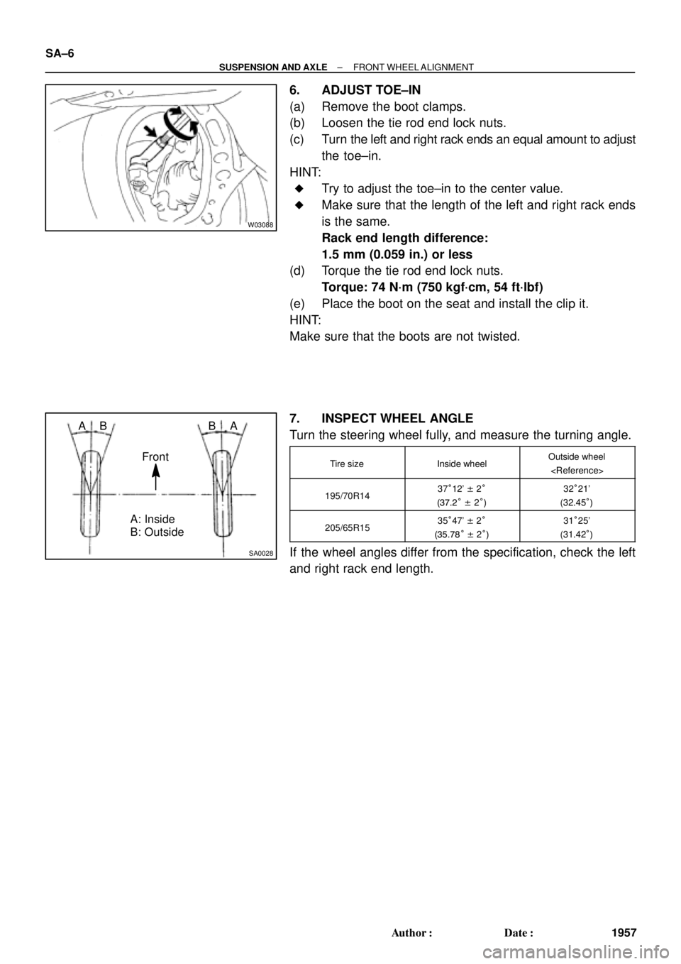
A: Inside
B: Outside AB
Front BA SA±6
± SUSPENSION AND AXLEFRONT WHEEL ALIGNMENT
1957 Author�: Date�:
6. ADJUST TOE±IN
(a) Remove the boot clamps.
(b) Loosen the tie rod end lock nuts.
(c) Turn the left and right rack ends an equal amount to adjust
the toe±in.
HINT:
�Try to adjust the toe±in to the center value.
�Make sure that the length of the left and right rack ends
is the same.
Rack end length difference:
1.5 mm (0.059 in.) or less
(d) Torque the tie rod end lock nuts.
Torque: 74 N´m (750 kgf´cm, 54 ft´lbf)
(e) Place the boot on the seat and install the clip it.
HINT:
Make sure that the boots are not twisted.
7. INSPECT WHEEL ANGLE
Turn the steering wheel fully, and measure the turning angle.
Tire sizeInside wheelOutside wheel
195/70R1437°12' ± 2°
(37.2° ± 2°)32°21'
(32.45°)
205/65R1535°47' ± 2°
(35.78° ± 2°)31°25'
(31.42°)
If the wheel angles differ from the specification, check the left
and right rack end length.
Page 4677 of 4770

Toyota Supports ASE CertificationPage 1 of 2
SS002±99Title:
1999 SPECIAL SERVICE TOOLS
Models:
All '98 & '99 Models
Technical Service
BULLETIN
July 9, 1999
This TSB contains information regarding Special Service Tools (SSTs) distributed or
added to the SST program during 1999 model year. Both the Essential and Available
SSTs are listed by tool number, tool name, and model application.
Special Service Tools can be ordered through the Toyota SST Program by calling
1±800±933±8335.
�All 1998 and 1999 MY Toyota Vehicles.
1999 ESSENTIAL SPECIAL SERVICE TOOLS
TOOL NUMBERTOOL NAMEAPPLICATION
09521±25021±1Rear Axle Shaft Puller AttachmentLand Cruiser
09631±12090Seal Ring ToolLand Cruiser
09710±28012±01Front Suspension Bushing Tool SetLand Cruiser
02002±02XXXHaweka Flange Plate
Note: XXX is Spindle Shaft Size
Land Cruiser
09950±60030±01Replacer Set #3Land Cruiser
09999±00310Toyota Spare Tire Lock KitLand Cruiser,
T100, Tacoma
09999±00305
Part of Kit #
09999±00310Spare Tire Lock Adapter
(Toyota/Lexus Dual Dealers)T100
09268±21010±01Fuel Hose PullerCorolla ('99)
SPECIAL SERVICE TOOLS
Introduction
Applicable
Vehicles
1999 Essential
Special Service
Tools