Page 3216 of 4770
H08301
LG±R P±B
B
BJ3 Junction
ConnectorAirbag Sensor
Assembly
A2119
Tc
11
LG±R 11
Tc
E1DLC1
3 BR
A
J22 (1MZ±FE)
J23 (5S±FE)
Junction Connector
BR (*4)
ECEC BR A
Junction
Connector
6
J7B
J8 C
BR 3
E1Tc DLC2 LG±R (*1)
P±B (*2)
4
B II3
II3
BR
J22
Junction Connector
A A BR BR (*3)J26
Junction
ConnectorB
B
BR (*3)
*1: TMC Made
*2: TMMK Made
*3: California, 1MZ±FE
*4: Except California DI±796
± DIAGNOSTICSSUPPLEMENTAL RESTRAINT SYSTEM
1031 Author�: Date�:
Tc Terminal Circuit
CIRCUIT DESCRIPTION
By connecting terminals Tc and E1 of the DLC1 the airbag sensor assembly is set in the DTC output mode.
The DTCs are displayed by blinking the SRS warning light.
WIRING DIAGRAM
DI1BQ±08
Page 3217 of 4770
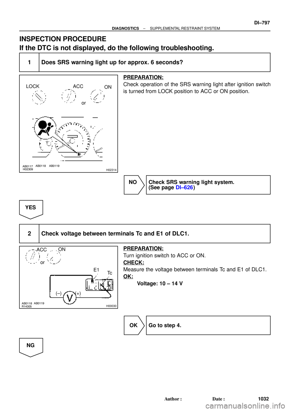
AB0117AB0118AB0119
H02309H02314
LOCK ACC
ON
or
AB0118
R14305AB0119
H00030
ACCON
or
E1
Tc
(+) (±)
± DIAGNOSTICSSUPPLEMENTAL RESTRAINT SYSTEM
DI±797
1032 Author�: Date�:
INSPECTION PROCEDURE
If the DTC is not displayed, do the following troubleshooting.
1 Does SRS warning light up for approx. 6 seconds?
PREPARATION:
Check operation of the SRS warning light after ignition switch
is turned from LOCK position to ACC or ON position.
NO Check SRS warning light system.
(See page DI±626)
YES
2 Check voltage between terminals Tc and E1 of DLC1.
PREPARATION:
Turn ignition switch to ACC or ON.
CHECK:
Measure the voltage between terminals Tc and E1 of DLC1.
OK:
Voltage: 10 ± 14 V
OK Go to step 4.
NG
Page 3218 of 4770

(±)
AB0117 AB0118 AB0119H01302H01303
LOCK
ACCON
or
Airbag Sensor Assembly
Tc
DI±798
± DIAGNOSTICSSUPPLEMENTAL RESTRAINT SYSTEM
1033 Author�: Date�:
3 Check")
AB0118
R14304AB0119
H00031
ACCON
orTc
(+)
(±)
AB0117 AB0118 AB0119H01302H01303
LOCK
ACCON
or
Airbag Sensor Assembly
Tc
DI±798
± DIAGNOSTICSSUPPLEMENTAL RESTRAINT SYSTEM
1033 Author�: Date�:
3 Check voltage between terminal Tc of DLC1 and body ground.
CHECK:
Measure the voltage between terminal Tc of DLC1 and body
ground.
OK:
Voltage: 10 ± 14 V
OK Check harness between terminal E1 of DLC1
and body ground.
NG
4 Check airbag sensor assembly.
PREPARATION:
(a) Turn ignition switch to LOCK.
(b) Disconnect negative (±) terminal cable from the battery,
and wait at least for 90 seconds.
(c) Disconnect the airbag sensor assembly connector.
(d) Insert service wire into terminal Tc from back side as
shown in the illustration.
(e) Connect the airbag sensor assembly connector with ser-
vice wire.
(f) Connect negative (±) terminal cable to the battery.
(g) Turn ignition switch to ACC or ON and wait at least for 20
seconds.
(h) Connect service wire of terminal Tc to body ground.
CHECK:
Check operation of SRS warning light.
OK:
SRS waning light comes on.
NOTICE:
Pay due attention to the terminal connecting position to
avoid a malfunction.
OK Check harness between the airbag sensor as-
sembly and DLC1.
NG
Replace airbag sensor assembly.
Page 3242 of 4770
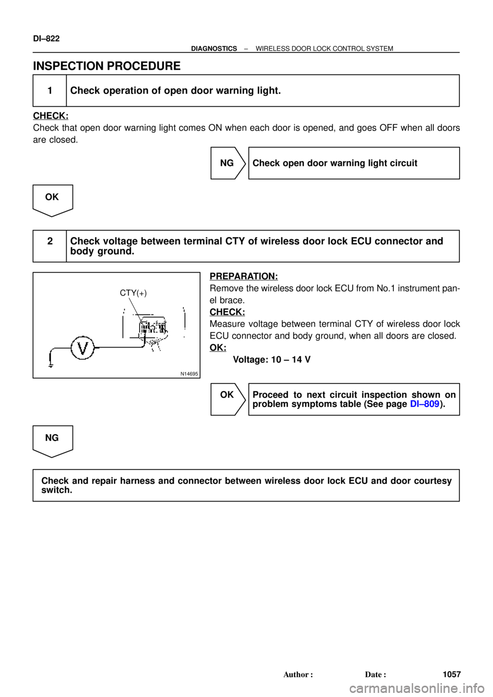
N14695
CTY(+)
DI±822
± DIAGNOSTICSWIRELESS DOOR LOCK CONTROL SYSTEM
1057 Author�: Date�:
INSPECTION PROCEDURE
1 Check operation of open door warning light.
CHECK:
Check that open door warning light comes ON when each door is opened, and goes OFF when all doors
are closed.
NG Check open door warning light circuit
OK
2 Check voltage between terminal CTY of wireless door lock ECU connector and
body ground.
PREPARATION:
Remove the wireless door lock ECU from No.1 instrument pan-
el brace.
CHECK:
Measure voltage between terminal CTY of wireless door lock
ECU connector and body ground, when all doors are closed.
OK:
Voltage: 10 ± 14 V
OK Proceed to next circuit inspection shown on
problem symptoms table (See page DI±809).
NG
Check and repair harness and connector between wireless door lock ECU and door courtesy
switch.
Page 3247 of 4770

DI06N±05
THEFT DETERRENT SYSTEM Check Sheet
Inspector 's name:
Customer 's Name
Date of VehicleRegistration No.
Registration Year
Frame No.
Odometer Reading / /km
Mile
Weather Conditions
When Problem
Occurred Frequency Problem OccursWeather
Outdoor temperature
/ /
� Constant � Sometimes ( Times per day, month)
� Once only Brought in
� Theft deterrent system cannot be set.
� Indicator light does not flash when the theft deterrent system is set.
(It stays on or does not light at all.)
� Theft deterrent system
does not operate.� When unlocked using the
door lock knob.
� When the engine hood is
opened.
� System cannot be
canceled once set.� When door is unlocked using key or wireless door lock control system.
� When the key is inserted in the ignition key cylinder and turned to ACC or ON
position.
(However, only when the system has never operated)
� When the luggage compartment door is opened with the key.
� System cannot be
canceled during warning
operation.� When door is unlocked using key or wireless door lock control system.
� When the key is inserted in the ignition key cylinder and turned to ACC or ON
position.
� Warning operation starts when the system is set and the door or luggage compartment door is opened with
the key.
� Others.
Date Problem First Occurred
� Fine � Cloudy � Rainy � Snowy
� Various/Others
� Hot � Warm � Cool
� Cold (Approx. 5F ( 5C))
Problem Symptom
Malfunction
� Horns only
� Theft deterrent horn only
� Headlights only
� Taillights only
� Starter cut only
� Door lock operation only
± DIAGNOSTICSTHEFT DETERRENT SYSTEM
DI±827
1062 Author�: Date�:
CUSTOMER PROBLEM ANALYSIS CHECK
Page 3253 of 4770
DI06P±05
I00233
I00234
I00236
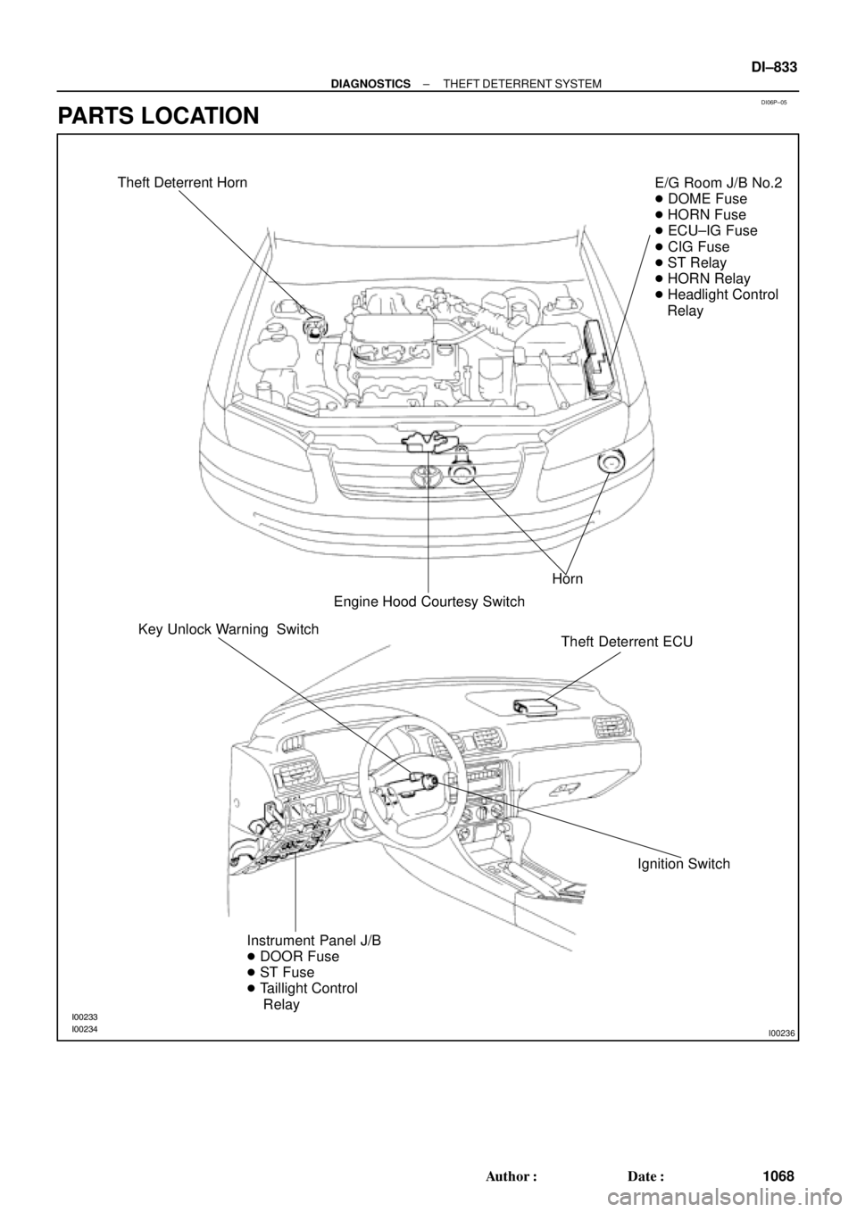
Theft Deterrent Horn
Horn
Engine Hood Courtesy SwitchE/G Room J/B No.2
� DOME Fuse
� HORN Fuse
� ECU±IG Fuse
� CIG Fuse
� ST Relay
� HORN Relay
� Headlight Control
Relay
Theft Deterrent ECU
Ignition Switch Key Unlock Warning Switch
Instrument Panel J/B
� DOOR Fuse
� ST Fuse
� Taillight Control
Relay
± DIAGNOSTICSTHEFT DETERRENT SYSTEM
DI±833
1068 Author�: Date�:
PARTS LOCATION
Page 3257 of 4770

DI06R±06
Details of Problem
The theft deterrent system cannot be set
Inspecting Circuit*1See page
DI±838 1. Indicator light circuit
2. ECU power source circuit
3. Key unlock warning switch circuit
7. Door courtesy switch circuit
8. Door unlock detection switch circuit
9. Engine hood courtesy switch circuit
The indicator light does not blink when system is setIndicator light circuit
When the
system is
set
When the rear doors are unlocked
When the luggage compartment door is opened
by a method other than the key4. Luggage compartment door key
lock and unlock switch circuit
5. Luggage compartment door
courtesy switch circuit
When the engine hood is opened
The system
does not
operateDoor unlock detection switch circuit
Luggage compartment door
courtesy switch circuit
Engine hood courtesy switch circuit
While the system is
in warning operation
Horns do not sound
Theft deterrent horn does not sound
Headlights do not flash
Taillights do not flash
The door lock is not locked in unlock conditionHorn relay circuit
Theft deterrent horn circuit
Headlight control relay circuit
Taillight control relay circuit
Door unlock detection switch circuit
6. Door key lock and unlock switch
circuit
It is not canceled when the ignition key is turned to
ACC or ON position
It still operates when the luggage compartment door is
opened with the key When the
system is
set
Ignition switch circuit
Luggage compartment door key
lock and unlock switch circuit
System is still set even when a rear door is open
Door courtesy switch circuit
Even when the
system is not
setHorns sound
Theft deterrent horn sounds
Headlights stay on
Taillights stay onHorn relay circuit
Theft deterrent horn circuit
Headlight control relay circuit
Taillight control relay circuit
DI±840
DI±853
DI±855
DI±858
DI±855
DI±864
DI±862
DI±866
DI±838
DI±862
DI±858
DI±866
DI±845
DI±843
DI±847
DI±849
DI±862
DI±851
DI±855
DI±864
DI±845
DI±843
DI±847
DI±849
*1: If numbers are given to the circuit proceed with troubleshooting in the order indicated by those numbers.
± DIAGNOSTICSTHEFT DETERRENT SYSTEM
DI±837
1072 Author�: Date�:
PROBLEM SYMPTOMS TABLE
Proceed to the reference page shown in the matrix chart below for each malfunction symptom and trouble-
shoot for each circuit.
HINT:
Troubleshooting of the theft deterrent system is based on the premise that the door lock control system is
operating normally. Accordingly, before troubleshooting the theft deterrent system, first make certain that
the door lock control system is operating normally.
Page 3285 of 4770
± DIAGNOSTICSTHEFT DETERRENT SYSTEM
DI±865
1100 Author�: Date�:
INSPECTION PROCEDURE
1 Check operation of open door warning light.
CHECK:
Check that open door warning light comes ON when each door is opened, and goes OFF when all doors
are closed.
NG Check and repair open door warning light cir-
cuit.
OK
2 Check for open in harness and connector between theft deterrent ECU and door
courtesy switch (See page IN±31).
NG Repair or replace harness or connector.
OK
Check and replace theft deterrent ECU.*1
*1: When there is a malfunction that the theft deterrent system
cannot be set, proceed to the next numbered circuit inspection
shown on problem symptoms table (See page DI±837).

J23 (5S±FE)
Junction Connector
BR (*4)
ECEC BR A
Junction
Connector
6
J7B
J8 C
BR")