Page 2809 of 4770

DI02W±02
FI0534
S05335
TOYOTA hand±held tester
DLC3
± DIAGNOSTICSAUTOMATIC TRANSAXLE (A140E)
DI±389
624 Author�: Date�:
PRE±CHECK
1. DIAGNOSIS SYSTEM
(a) Description
�When troubleshooting OBD II vehicles, the only dif-
ference from the usual troubleshooting procedure
is that you connect an OBD II scan tool complying
with SAE J1987 or TOYOTA hand±held tester to the
vehicle, and read off various data output from the
vehicle's ECM.
OBD II regulations require that the vehicle's on±
board computer lights up the Malfunction Indicator
Lamp (MIL) on the instrument panel when the com-
puter detects a malfunction in the computer itself or
in drive system components which affect vehicle
emissions. In addition to the MIL lighting up when
a malfunction is detected, the applicable DTCs pre-
scribed by SAE J2012 are recorded in the ECM
memory (See page DI±16).
If the malfunction only occurs in 3 trips, the MIL goes
off but the DTCs remain recorded in the ECM
memory.
�To check the DTCs, connect an OBD II scan tool or
TOYOTA hand±held tester to DLC3 on the vehicle.
The OBD II scan tool or TOYOTA hand±held tester
also enables you to erase the DTCs and check
freeze frame data and various forms of engine data
(For instruction book).
DTCs include SAE controlled codes and Manufac-
turer controlled codes.
SAE controlled codes must be set as the codes pre-
scribed by the SAE, while Manufacturer controlled
codes can be set freely by the manufacturer within
the prescribed limits.
(See DTC chart on page DI±401)
Page 2846 of 4770

D00043 Q08479BE3840D00994
w/ Engine Immobiliser System
w/o Engine Immobiliser SystemON
NSW
LL
2
R
NSWR
2
(±)(+) (+)
(±)
Position
P, N
R
D
2
LNSW±Body
groundR±Body
ground2±Body
groundL±Body
ground
0 V
0 V0 V0 V
0 V
0 V
0 V 0 V
0 V
0 V 0 V
0 V
0 V 9 ~ 14 V*
9 ~ 14 V
9 ~ 14 V
9 ~ 14 V9 ~ 14 V
9 ~ 14 V 9 ~ 14 V*
DI±426
± DIAGNOSTICSAUTOMATIC TRANSAXLE (A140E)
661 Author�: Date�:
INSPECTION PROCEDURE
1 Read PNP, REVERSE, 2ND and LOW signals.
When using TOYOTA hand±held tester:
PREPARATION:
(a) Remove the DLC3 cover.
(b) Connect a TOYOTA hand±held tester to the DLC3.
(c) Turn the ignition switch ON and TOYOTA hand±held tes-
ter main switch ON.
CHECK:
Shift the shift lever into the P, R, N, 2 and L positions, and read
the PNP, REVERSE, 2ND and LOW signals on the TOYOTA
hand±held tester.
OK:
Shift positionSignal
22ND OFF " ON
LLOW OFF " ON
RREVERSE OFF " ON
P, NPNP OFF " ON
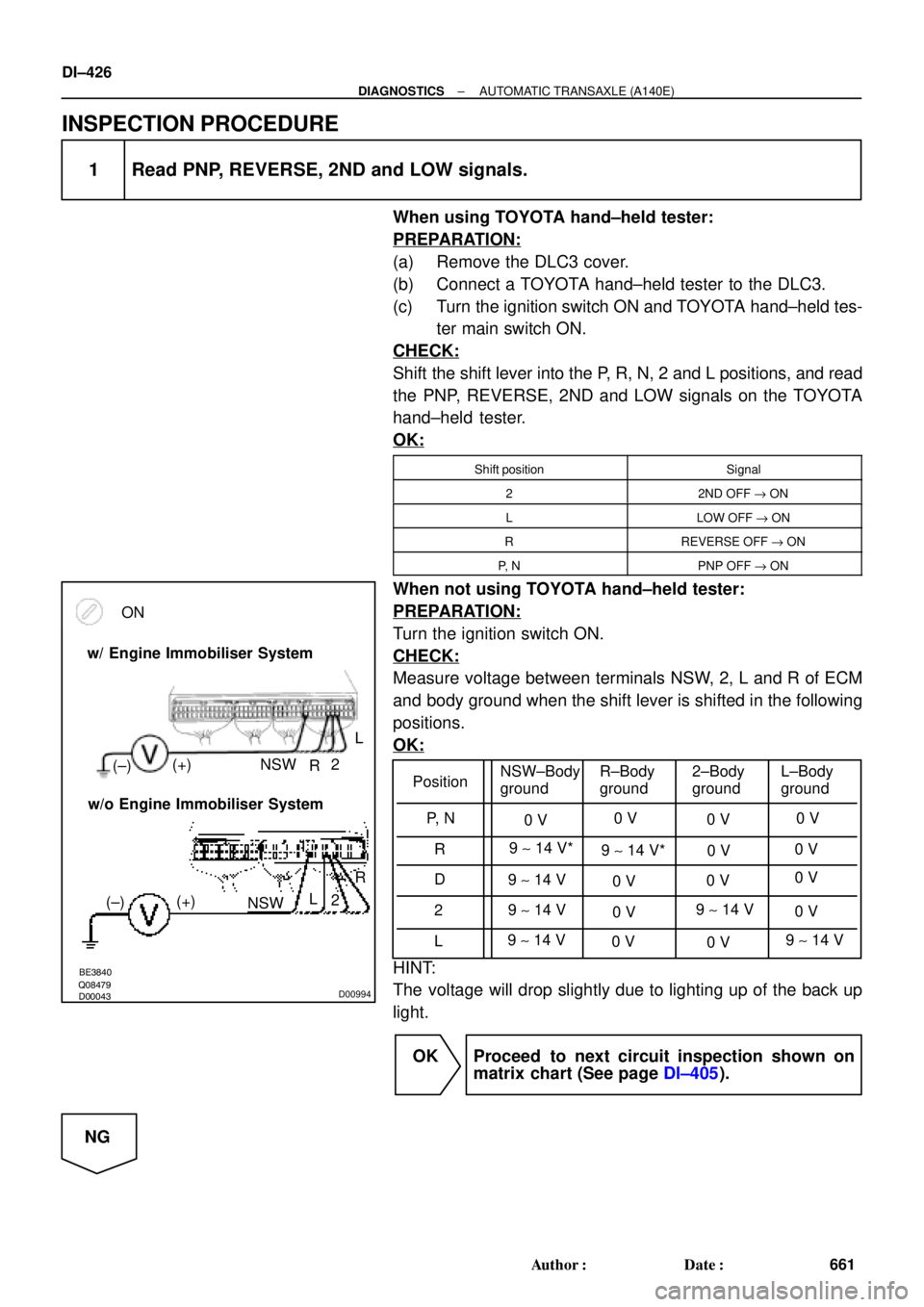
When not using TOYOTA hand±held tester:
PREPARATION:
Turn the ignition switch ON.
CHECK:
Measure voltage between terminals NSW, 2, L and R of ECM
and body ground when the shift lever is shifted in the following
positions.
OK:
HINT:
The voltage will drop slightly due to lighting up of the back up
light.
OK Proceed to next circuit inspection shown on
matrix chart (See page DI±405).
NG
Page 2858 of 4770

FI0534
DI02E±02
S05335
TOYOTA hand±held tester
DLC3
DI±438
± DIAGNOSTICSAUTOMATIC TRANSAXLE (A541E)
673 Author�: Date�:
PRE±CHECK
1. DIAGNOSIS SYSTEM
(a) Description
�When troubleshooting OBD II vehicles, the only dif-
ference from the usual troubleshooting procedure
is that you connect to the vehicle an OBD II scan
tool complying with SAE J1987 or TOYOTA hand±
held tester, and read off various data output from
the vehicle's ECM.
OBD II regulations require that the vehicle's on±
board computer lights up the Malfunction Indicator
Lamp (MIL) on the instrument panel when the com-
puter detects a malfunction in the computer itself or
in drive system components which affect vehicle
emissions. In addition to the MIL lighting up when
a malfunction is detected, the applicable DTCs pre-
scribed by SAE J2012 are recorded in the ECM
memory. (See page DI±211)
If the malfunction only occurs in 3 trips, the MIL goes
off but the DTCs remain recorded in the ECM
memory.
�To check the DTCs, connect an OBD II scan tool or
TOYOTA hand±held tester to DLC3 on the vehicle.
The OBD II scan tool or TOYOTA hand±held tester
also enables you to erase the DTCs and check
freeze frame data and various forms of engine data
(For instruction book).
DTCs include SAE controlled codes and Manufac-
turer controlled codes.
SAE controlled codes must be set as prescribed by
the SAE, while Manufacturer controlled codes can
be set freely by the manufacturer within the pre-
scribed limits (See DTC chart on page DI±449).
Page 2902 of 4770

BE3840D00052D00836D01914
Except California, w/ Engine Immobilizer
and / or TRAC:
California, w/ Engine Immobilizer
and / or TRAC:ON
L
NSW
2
R
2R
L
NSW
Position
P, N
R
D
2
LNSW±Body
groundR±Body
ground2±Body
groundL±Body
ground
0 V
0 V0 V0 V
0 V
0 V
0 V 0 V
0 V
0 V 0 V
0 V
0 V 9 ~ 14 V*
9 ~ 14 V
9 ~ 14 V
9 ~ 14 V9 ~ 14 V
9 ~ 14 V 9 ~ 14 V* DI±482
± DIAGNOSTICSAUTOMATIC TRANSAXLE (A541E)
717 Author�: Date�:
INSPECTION PROCEDURE
1 Read PNP, REVERSE, 2ND and LOW signals.
When using TOYOTA hand±held tester.
PREPARATION:
(a) Remove the DLC3 cover.
(b) Connect a TOYOTA hand±held tester to the DLC3.
(c) Turn the ignition switch ON and TOYOTA hand±held tes-
ter main switch ON.
CHECK:
Shift lever into the P, R, N, 2 and L positions, and read the PNP,
REVERSE, 2ND and LOW signals on the TOYOTA hand±held
tester.
OK:
Shift positionSignal
22ND OFF " ON
LLOW OFF " ON
RREVERSE OFF " ON
P, NNSW OFF " ON
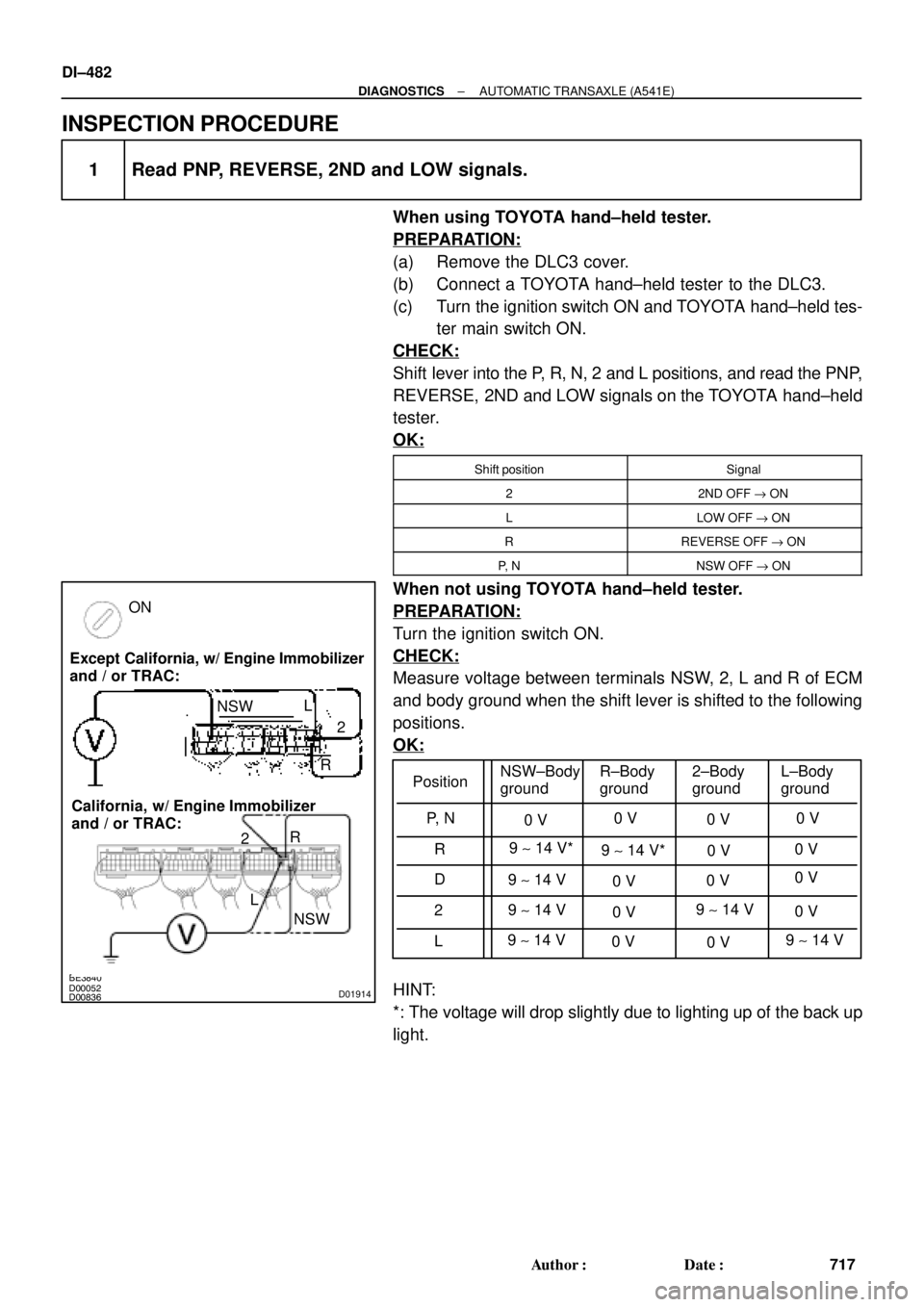
When not using TOYOTA hand±held tester.
PREPARATION:
Turn the ignition switch ON.
CHECK:
Measure voltage between terminals NSW, 2, L and R of ECM
and body ground when the shift lever is shifted to the following
positions.
OK:
HINT:
*: The voltage will drop slightly due to lighting up of the back up
light.
Page 4452 of 4770

Toyota Supports ASE CertificationPage 1 of 1
BO007±99
Title:
TMMK CAMRY/SIENNA HEADLIGHT
ALIGNMENT
Models:
'97±'99 Camry, '98±'99 Sienna
Technical Service
BULLETIN
April 16, 1999
To enhance headlamp performance on dark roads, the headlamp alignment process has
been modified.
�1997±1999 TMMK Camrys produced before the following VINs:
Camry (4±Cyl) 4T1BG2 * K * XU453367
Camry (V±6) 4T1BF2 * K * XU079094
Camry (4±Cyl) 4T1BG2 * K * XU877828
Camry (V±6) 4T1BF2 * K * XU930732
�1998±1999 Siennas produced before the following VIN:
Sienna 4T3ZF13C * XU119213
Headlight Aiming Device.
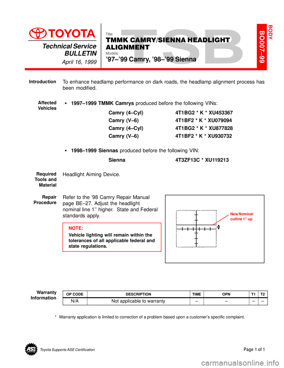
Refer to the '98 Camry Repair Manual
page BE±27. Adjust the headlight
nominal line 1'' higher. State and Federal
standards apply.
NOTE:
Vehicle lighting will remain within the
tolerances of all applicable federal and
state regulations.
OP CODEDESCRIPTIONTIMEOPNT1T2
N/ANot applicable to warranty±±±±
* Warranty application is limited to correction of a problem based upon a customer's specific complaint.
BODY
Introduction
Affected
Vehicles
Required
Tools and
Material
Repair
Procedure
New Nominal
cutline 1'' up
Warranty
Information