Page 124 of 4770
13. TEMPORARILY INSTALL NO.1 IDLER PULLEY AND
TENSION SPRING
(a) Install the pulley with the bolt. Do not tighten the bolt
yet.
HINT: Use bolt 42 mm (1.65 in.) in length.
(b) Install the tension spring.
(c) Pry the pulley toward the left as far as it will go and
tighten the bolt.
(d) Check that the idler pulley moves smoothly.
14. INSTALL CAMSHAFT TIMING PULLEY AND
TIMING BELT
(See page EG1±33)
15. INSTALL INJECTORS AND DELIVERY PIPE
(a) California:
Install new insulator and grommet to each injector.
(b) Except California:
Install a new grommet to each injector.
(c) California:
Apply a light coat of gasoline to 2 new 0±rings, and
install them to each injector.
(d) Except California:
Apply a light coat of gasoline to a new 0±ring, and
install it to each injector.
(e) While turning the injector left and right, install it to the
delivery pipes. Install the 4 injectors.
± 5S±FE ENGINEENGINE MECHANICALEG1±74
Page 193 of 4770
Backlash
Crankshaft x No. 1 balance shaft
Off±vehicle
On±vehicle
No. 1 balance shaft x No.2 balance shaft
at D mark
at E mark
at F mark
Spacer thickness
Engine moving control rod x No. 2 engine mounting bracketCamshaft timing pulley x Camshaft (For use with SST)
TORQUE SPECIFICATIONS
No. 2 engine mounting bracket x Cylinder blockBalance shaft housing bolt outer diameter
Engine moving control rod X Fender apronOil pump pulley x Oil pump drive 'shaft Cylinder head cover x Cylinder head
Cylinder head x Cylinder block (1 styCamshaft timing pulley x Camshaft No. 2 idler pulley x Cylinder block
No. 1 idler pulley x Cylinder heedCrankshaft pulley x Crankshaft Spark plug x Cylinder headEngine
balancerThrust clearance
Part tightened
± 5S±FE ENGINEENGINE MECHANICALEG1±143
Page 521 of 4770

42ENGINEÐ5S±FE ENGINE
5. Main Components of Engine Control System
The following table compares the main components of the new 5S±FE engine, and previous 5S±FE engine.
Model
NewPreviousComponentNewPrevious
Manifold Absolute Pressure SensorSemiconductoru
Throttle Position SensorLinear Typeu
Crankshaft Position SensorPick±Up Coil Type, 1u
Camshaft Position SensorPick±Up Coil Type, 1Ð
DistributorCamshaft PositionPick Up Coil Type 1DistributorSensorÐPick±Up Coil Type, 1
Knock SensorBuilt±In Piezoelectric
Element Type 1u
Oxygen Sensor
Heated Oxygen Sensor
(Bank 1, Sensor 1)*
1
(Bank 1, Sensor 2)
Air Fuel Ratio Sensor*
2
Oxygen Sensor
(Bank 1, Sensor 1)
(Bank 1, Sensor 2)
Injector2±Hole Typeu
IAC ValveRotary Solenoid Typeu
*1: Except for California Specification Models.
*
2: Only for California Specification Models.
Camshaft Position Sensor
The camshaft position sensor is mounted onto the
cylinder head. Using the protusion that is provided
on the timing pulley, the sensor generates 1 signal
for every revolution. This signal is then sent to the
ECM as a cranskshaft angle system.
Page 2386 of 4770
B06388
No.2 Timing Belt CoverTiming Belt
Gasket
Timing Belt Guide
No.2 Generator
Bracket RH Engine Mounting Bracket
Crankshaft
PulleyGasket
Engine Wire Protector
RH Camshaft Timing PulleyNo.2 Idler Pulley
Dust Boot
Timing Belt Tensioner
� Non±reusable part
*For use with SSTNo.1 Timing Belt Cover
LH Camshaft
Timing Pulley
N´m (kgf´cm, ft´lbf) : Specified torque
28 (290, 21)
215 (2,200, 159)
125 (1,300, 94)*88 (900, 65)
43 (440, 32)
27 (280, 20)
125 (1,300, 94)
CO±4
± COOLING (1MZ±FE)WATER PUMP
1612 Author�: Date�:
Page 2388 of 4770
CO03E±03
P12942
CO±6
± COOLING (1MZ±FE)WATER PUMP
1614 Author�: Date�:
REMOVAL
1. DRAIN ENGINE COOLANT
2. REMOVE TIMING BELT (See page EM±15)
3. REMOVE CAMSHAFT TIMING PULLEYS
(See page EM±15)
4. REMOVE NO.2 IDLER PULLEY
(See page EM±15)
5. REMOVE NO.3 TIMING BELT COVER
(See page EM±32)
6. REMOVE WATER PUMP
Remove the 4 bolts, 2 nuts, water pump and gasket.
Page 2390 of 4770
CO0SO±01
P12942
CO±8
± COOLING (1MZ±FE)WATER PUMP
1616 Author�: Date�:
INSTALLATION
1. INSTALL WATER PUMP
Install a new gasket and the water pump with the 4 bolts and 2
nuts.
Torque: 8 N´m (80 kgf´cm, 69 in.´lbf)
NOTICE:
Do not get oil on the gasket.
2. INSTALL NO.3 TIMING BELT COVER
(See page EM±57)
3. INSTALL NO.2 IDLER PULLEY
(See page EM±21)
4. INSTALL CAMSHAFT TIMING PULLEYS
(See page EM±21)
5. INSTALL TIMING BELT
(See page EM±21)
6. FILL WITH ENGINE COOLANT
7. START ENGINE AND CHECK FOR LEAKS
8. RECHECK ENGINE COOLANT LEVEL
Page 2524 of 4770

339 Author�: Date�:
INSPECTION PROCEDURE
HINT:
Read freeze frame data using TOYOTA hand±held tester or OBD II scan tool. Because freeze frame records
the engine")
DI±104
± DIAGNOSTICSENGINE (5S±FE)
339 Author�: Date�:
INSPECTION PROCEDURE
HINT:
Read freeze frame data using TOYOTA hand±held tester or OBD II scan tool. Because freeze frame records
the engine conditions when the malfunction is detected, when troubleshooting it is useful for determining
whether the vehicle was running or stopped, the engine warmed up or not, the air±fuel ratio lean or rich, etc.
at the time of the malfunction.
1 Check resistance of camshaft position sensor (signal generator)
(See page IG±1).
Reference: INSPECTION USING OSCILLOSCOPE
Refer to DTC P0335 (Crankshaft Position Sensor ºAº Circuit Malfunction) on page DI±100.
NG Replace camshaft position sensor.
OK
2 Check for open and short in harness and connector between ECM and camshaft
position sensor (See page IN±31).
NG Repair or replace harness or connector.
OK
3 Inspect sensor installation and tooth of camshaft timing pulley
(See pages IG±9 and EM±17).
NG Tighten the sensor. Replace camshaft timing
pulley.
OK
Check and replace ECM (See page IN±31).
Page 2711 of 4770
± DIAGNOSTICSENGINE (1MZ±FE)
DI±291
526 Author�: Date�:
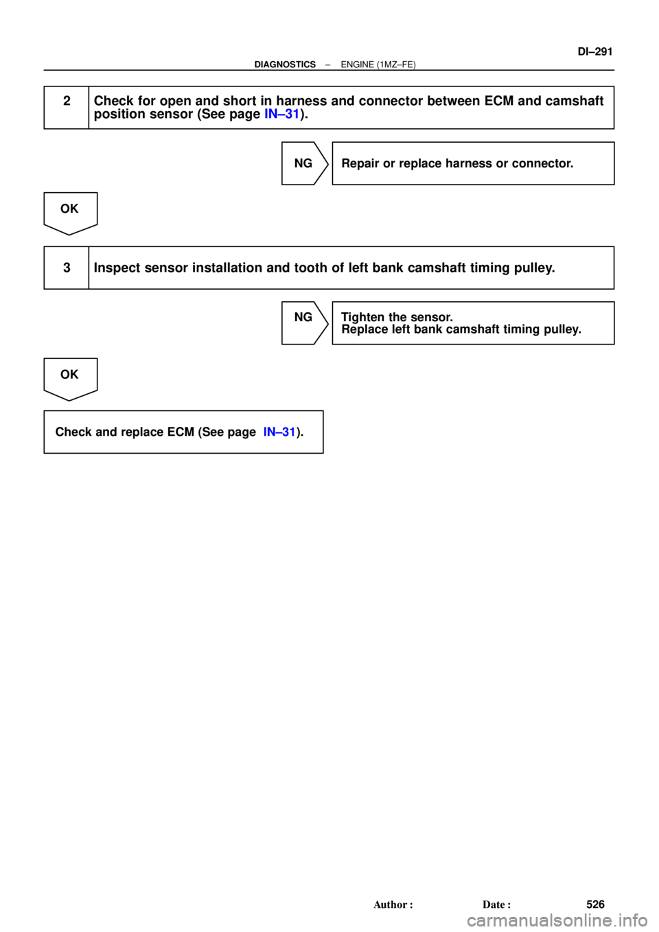
2 Check for open and short in harness and connector between ECM and camshaft
position sensor (See page IN±31).
NG Repair or replace harness or connector.
OK
3 Inspect sensor installation and tooth of left bank camshaft timing pulley.
NG Tighten the sensor.
Replace left bank camshaft timing pulley.
OK
Check and replace ECM (See page IN±31).
 Install the pulley with the bolt. Do not tighten the bolt
yet.
HINT: Use bolt 42 mm (1.65 in.) in length.
(b) Install the tension")