Page 4395 of 4770
Z00212
SST
SA088±01
Z00213
± SUSPENSION AND AXLEREAR WHEEL HUB BOLT
SA±55
2006 Author�: Date�:
REAR WHEEL HUB BOLT
REPLACEMENT
1. REMOVE REAR WHEEL
2. REMOVE REAR DISC OR DRUM (See page SA±52)
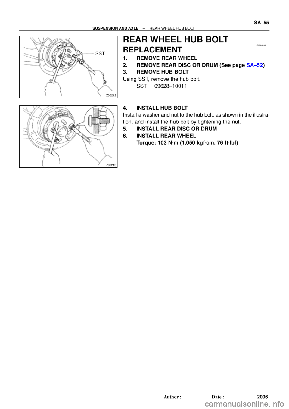
3. REMOVE HUB BOLT
Using SST, remove the hub bolt.
SST 09628±10011
4. INSTALL HUB BOLT
Install a washer and nut to the hub bolt, as shown in the illustra-
tion, and install the hub bolt by tightening the nut.
5. INSTALL REAR DISC OR DRUM
6. INSTALL REAR WHEEL
Torque: 103 N´m (1,050 kgf´cm, 76 ft´lbf)
Page 4396 of 4770
SA089±01
W03212
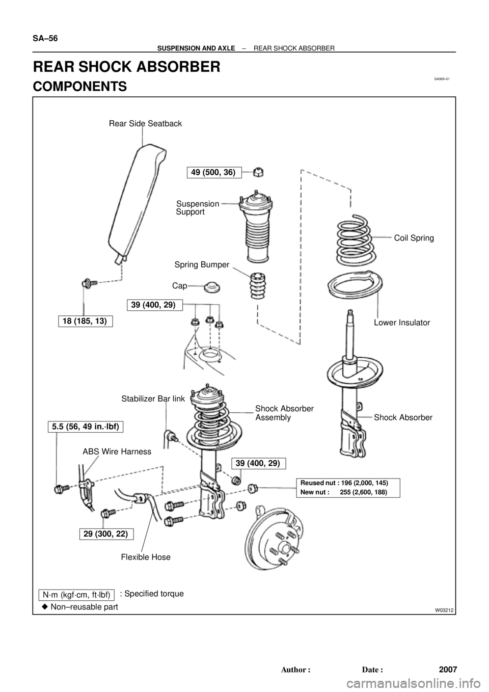
Spring Bumper
Lower Insulator
N´m (kgf´cm, ft´lbf): Specified torque
� Non±reusable partSuspension
Support
Coil Spring
Stabilizer Bar link
Assembly Shock Absorber Rear Side Seatback
Cap
Shock Absorber
ABS Wire Harness
Flexible Hose
49 (500, 36)
5.5 (56, 49 in.´lbf)
39 (400, 29)
29 (300, 22)
39 (400, 29)
Reused nut : 196 (2,000, 145)
New nut : 255 (2,600, 188)
18 (185, 13) SA±56
± SUSPENSION AND AXLEREAR SHOCK ABSORBER
2007 Author�: Date�:
REAR SHOCK ABSORBER
COMPONENTS
Page 4397 of 4770

2. REMOVE REAR WHEEL
Torque: 103")
SA08A±01
R00749
R10288
W03213
± SUSPENSION AND AXLEREAR SHOCK ABSORBER
SA±57
2008 Author�: Date�:
REMOVAL
1. REMOVE REAR SIDE SEATBACK
(See page BO±113 or BO±118)
2. REMOVE REAR WHEEL
Torque: 103 N´m (1,050 kgf´cm, 76 ft´lbf)
3. REMOVE FLEXIBLE HOSE AND ABS SPEED SEN-
SOR WIRE HARNESS (w/ ABS) FROM SHOCK AB-
SORBER
Remove the 2 bolts, flexible hose bracket and ABS wire har-
ness clamp.
Torque:
Flexible hose: 29 N´m (300 kgf´cm, 22 ft´lbf)
ABS wire: 5.5 N´m (56 kgf´cm, 49 in.´lbf)
4. DISCONNECT STABILIZER BAR LINK FROM SHOCK
ABSORBER (See page SA±70)
5. REMOVE SHOCK ABSORBER WITH COIL SPRING
(a) Loosen the 2 nuts on the lower side of the shock absorber.
Torque:
Reused nut: 196 N´m (2,000 kgf´cm, 145 ft´lbf)
New nut: 255 N´m (2,600 kgf´cm, 188 ft´lbf)
HINT:
At the time of installation, coat the nut's threads with engine oil.
(b) Support the rear axle carrier with a jack.
(c) Remove the cap.
(d) Loosen the nut in the middle of the suspension support.
NOTICE:
Do not remove it.
Torque: 49 N´m (500 kgf´cm, 36 ft´lbf)
(e) Remove the 3 nuts of the suspension support.
Torque: 39 N´m (400 kgf´cm, 29 ft´lbf)
(f) Lower the rear axle carrier and remove the 2 bolts.
(g) Remove the shock absorber with the coil spring.
Page 4398 of 4770
SA08B±01
W03214
SST SA±58
± SUSPENSION AND AXLEREAR SHOCK ABSORBER
2009 Author�: Date�:
DISASSEMBLY
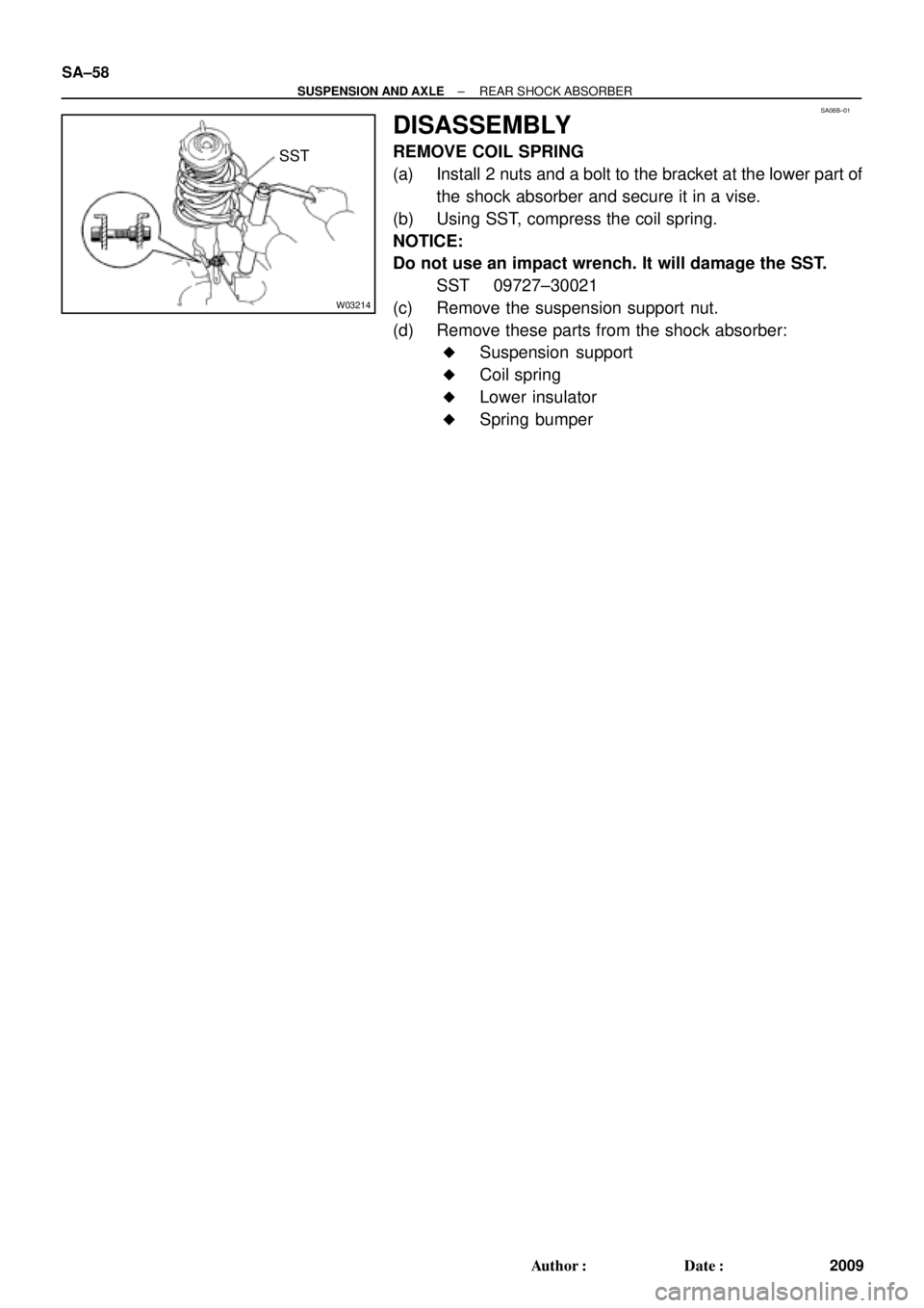
REMOVE COIL SPRING
(a) Install 2 nuts and a bolt to the bracket at the lower part of
the shock absorber and secure it in a vise.
(b) Using SST, compress the coil spring.
NOTICE:
Do not use an impact wrench. It will damage the SST.
SST 09727±30021
(c) Remove the suspension support nut.
(d) Remove these parts from the shock absorber:
�Suspension support
�Coil spring
�Lower insulator
�Spring bumper
Page 4399 of 4770
SA08C±01
W03646
± SUSPENSION AND AXLEREAR SHOCK ABSORBER
SA±59
2010 Author�: Date�:
INSPECTION
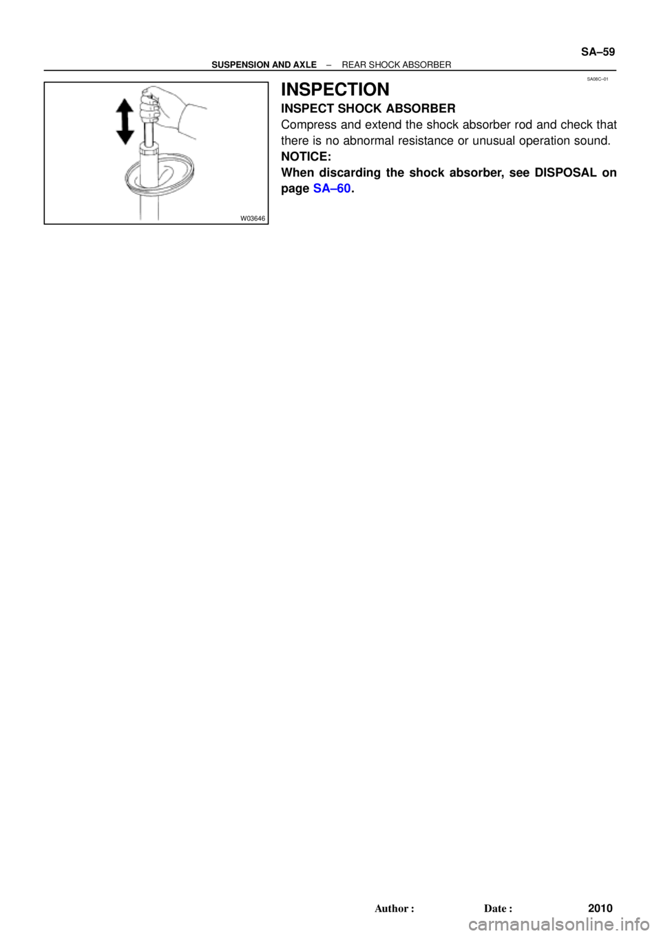
INSPECT SHOCK ABSORBER
Compress and extend the shock absorber rod and check that
there is no abnormal resistance or unusual operation sound.
NOTICE:
When discarding the shock absorber, see DISPOSAL on
page SA±60.
Page 4400 of 4770
SA0IJ±01
W03647
SA±60
± SUSPENSION AND AXLEREAR SHOCK ABSORBER
2011 Author�: Date�:
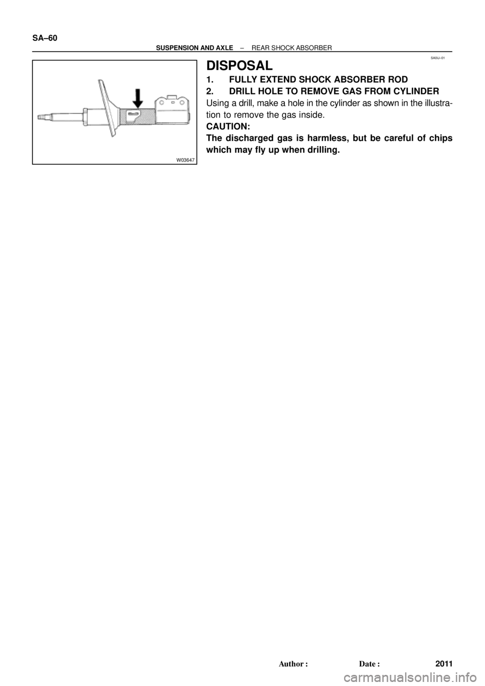
DISPOSAL
1. FULLY EXTEND SHOCK ABSORBER ROD
2. DRILL HOLE TO REMOVE GAS FROM CYLINDER
Using a drill, make a hole in the cylinder as shown in the illustra-
tion to remove the gas inside.
CAUTION:
The discharged gas is harmless, but be careful of chips
which may fly up when drilling.
Page 4401 of 4770
SA08E±01
R00911
SST
R00912
R00823
Outside I
± SUSPENSION AND AXLEREAR SHOCK ABSORBER
SA±61
2012 Author�: Date�:
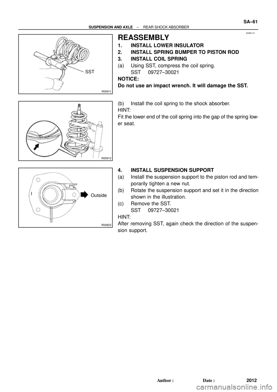
REASSEMBLY
1. INSTALL LOWER INSULATOR
2. INSTALL SPRING BUMPER TO PISTON ROD
3. INSTALL COIL SPRING
(a) Using SST, compress the coil spring.
SST 09727±30021
NOTICE:
Do not use an impact wrench. It will damage the SST.
(b) Install the coil spring to the shock absorber.
HINT:
Fit the lower end of the coil spring into the gap of the spring low-
er seat.
4. INSTALL SUSPENSION SUPPORT
(a) Install the suspension support to the piston rod and tem-
porarily tighten a new nut.
(b) Rotate the suspension support and set it in the direction
shown in the illustration.
(c) Remove the SST.
SST 09727±30021
HINT:
After removing SST, again check the direction of the suspen-
sion support.
Page 4402 of 4770
SA08F±01
SA±62
± SUSPENSION AND AXLEREAR SHOCK ABSORBER
2013 Author�: Date�:
INSTALLATION
Installation is in the reverse order of removal (See page SA±57).
AFTER INSTALLATION, CHECK REAR WHEEL ALIGNMENT (See page SA±7)