Page 123 of 447
AUTOMATIC TRANSMISSION (4 A/T) 7B-81
17) Remove thrust needle roller bearing (1) and thrust bearing
race (2) from the top of counter driven gear assembly (3).
18) Remove differential gear assembly (1).
19) Remove oil pump assembly and gasket (1).
20) Remove front clutch assembly (1).
21) Remove thrust bearing race (1) and thrust needle roller bear-
ing (2).
Page 124 of 447
7B-82 AUTOMATIC TRANSMISSION (4 A/T)
22) Remove rear clutch assembly (1).
23) Remove intermediate shaft assembly (1) and follow shaft
assembly (2).
24) Remove reverse brake (B2) snap ring, brake flange, brake
discs, brake plates and cushion plate.
25) Remove oil guide plate (1) parking lock pawl cover (2), shaft,
torsional spring (3) and parking lock pawl (4).
26) Remove parking lock pawl sleeve (5).
Page 126 of 447
7B-84 AUTOMATIC TRANSMISSION (4 A/T)
31) Remove rear cover assembly (1), thrust washer (2) and
thrust needle roller bearing (3).
Remove gasket (4).
32) Remove direct clutch (C0) assembly (1), thrust roller bearing
(2) and rear planetary sun gear No.1 assembly (3).
33) Remove planetary set (1) with bearing, thrust needle roller
bearing (2).
34) Remove O/D brake (B0) piston adapter (1), B0 plates (2)
and discs (3).
Page 129 of 447

AUTOMATIC TRANSMISSION (4 A/T) 7B-87
INSPECTION
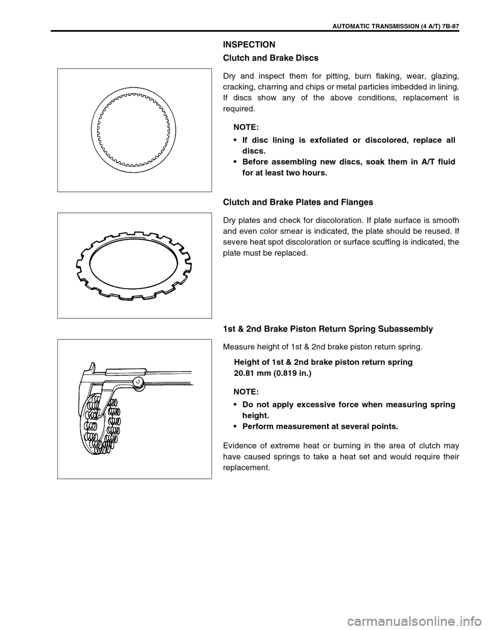
Clutch and Brake Discs
Dry and inspect them for pitting, burn flaking, wear, glazing,
cracking, charring and chips or metal particles imbedded in lining.
If discs show any of the above conditions, replacement is
required.
Clutch and Brake Plates and Flanges
Dry plates and check for discoloration. If plate surface is smooth
and even color smear is indicated, the plate should be reused. If
severe heat spot discoloration or surface scuffing is indicated, the
plate must be replaced.
1st & 2nd Brake Piston Return Spring Subassembly
Measure height of 1st & 2nd brake piston return spring.
Height of 1st & 2nd brake piston return spring
20.81 mm (0.819 in.)
Evidence of extreme heat or burning in the area of clutch may
have caused springs to take a heat set and would require their
replacement.NOTE:
If disc lining is exfoliated or discolored, replace all
discs.
Before assembling new discs, soak them in A/T fluid
for at least two hours.
NOTE:
Do not apply excessive force when measuring spring
height.
Perform measurement at several points.
Page 130 of 447

7B-88 AUTOMATIC TRANSMISSION (4 A/T)
DISASSEMBLY/ASSEMBLY OF SUBASSEMBLY
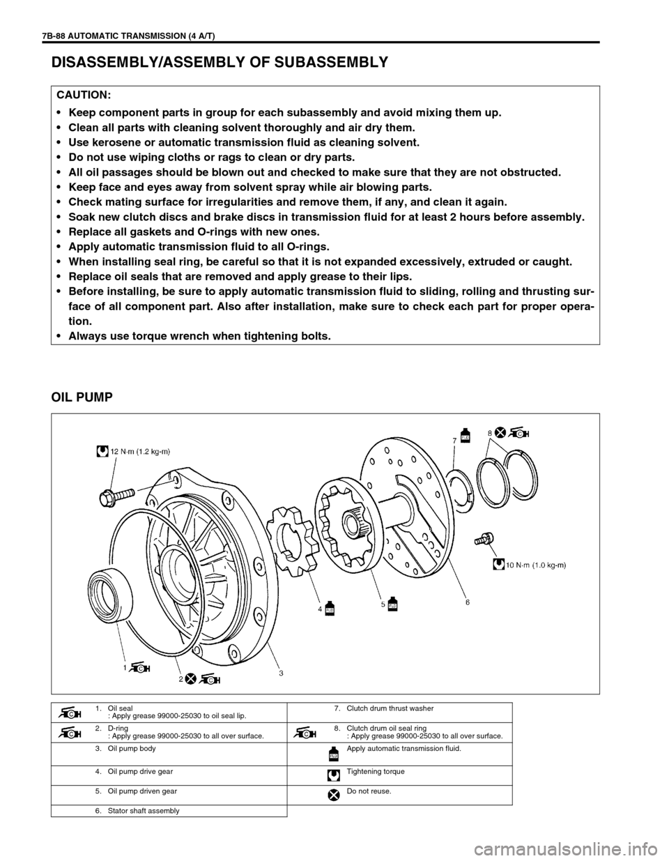
OIL PUMP
CAUTION:
Keep component parts in group for each subassembly and avoid mixing them up.
Clean all parts with cleaning solvent thoroughly and air dry them.
Use kerosene or automatic transmission fluid as cleaning solvent.
Do not use wiping cloths or rags to clean or dry parts.
All oil passages should be blown out and checked to make sure that they are not obstructed.
Keep face and eyes away from solvent spray while air blowing parts.
Check mating surface for irregularities and remove them, if any, and clean it again.
Soak new clutch discs and brake discs in transmission fluid for at least 2 hours before assembly.
Replace all gaskets and O-rings with new ones.
Apply automatic transmission fluid to all O-rings.
When installing seal ring, be careful so that it is not expanded excessively, extruded or caught.
Replace oil seals that are removed and apply grease to their lips.
Before installing, be sure to apply automatic transmission fluid to sliding, rolling and thrusting sur-
face of all component part. Also after installation, make sure to check each part for proper opera-
tion.
Always use torque wrench when tightening bolts.
1. Oil seal
: Apply grease 99000-25030 to oil seal lip.7. Clutch drum thrust washer
2. D-ring
: Apply grease 99000-25030 to all over surface. 8. Clutch drum oil seal ring
: Apply grease 99000-25030 to all over surface.
3. Oil pump body Apply automatic transmission fluid.
4. Oil pump drive gear Tightening torque
5. Oil pump driven gear Do not reuse.
6. Stator shaft assembly
Page 131 of 447

AUTOMATIC TRANSMISSION (4 A/T) 7B-89
DISASSEMBLY
1) Remove D-ring from pump body.
2) Remove 2 oil seal rings and clutch drum thrust washer.
3) Remove 11 bolts.
4) Separate pump body from stator shaft assembly.
5) Remove oil seal from pump body.
INSPECTION
1) Inspect pump body oil seal.
Check for wear, damage or cracks.
Replace oil seal if necessary and apply grease to its lip por-
tion slightly when it is installed.
2) Check body clearance of driven gear.
Push driven gear to one side of body. Using a feeler gauge,
measure clearance between driven gear and body.
If clearance exceeds its standard value, replace oil pump
assembly.
Clearance between oil pump driven gear and oil pump
body
Standard : 0.08 – 0.15 mm (0.0027 – 0.0059 in.)
Limit : 0.30 mm (0.018 in.)
3) Check tip clearance of both drive and driven gears.
Measure radial clearance between gear tooth and crescent.
If clearance exceeds its standard value, replace oil pump
assembly.
.Radial clearance between oil pump gear tooth and oil
pump crescent
Standard : 0.13 – 0.20 mm (0.0051 – 0.0079 in.)
Limit : 0.30 mm (0.018 in.)
4) Check side clearance of both gears.
Using a straightedge (1) and a feeler gauge (2), measure
side clearance between gear and pump body.
If clearance exceeds its standard value, replace oil pump
assembly.
Side clearance between gear and oil pump body
Standard : 0.02 – 0.04 mm (0.0008 – 0.0015 in.)
1. Oil pump drive gear
2. Driven gear
3. Body
1. Pump body crescent portion
Page 133 of 447
AUTOMATIC TRANSMISSION (4 A/T) 7B-91
FRONT CLUTCH (C2 CLUTCH)
DISASSEMBLY
1) Remove snap ring.
2) Remove flange (1), discs and plates.
3) Remove shaft snap ring (1).
Compress piston return springs and remove shaft snap ring.
Place special tool (clutch spring compressor) on spring seat
and compress spring with a press (2), and then remove shaft
snap ring, using a flat end rod or the like (3).
Special tool
(A) : 09926-96010
1. Front clutch No.1 drum 7. Clutch plate
2. D-ring
: Apply grease 99000-25030 to all over surface.8. Clutch disc
3. Front clutch piston
: Apply grease 99000-25030 to the lip of the piston.9. Clutch flange
4. Front clutch return spring seat 10. Snap ring
5. Front clutch balancer Apply automatic transmission fluid.
6. Shaft snap ring Do not reuse.
CAUTION:
Do not push down return spring more than necessary.
Page 134 of 447

7B-92 AUTOMATIC TRANSMISSION (4 A/T)
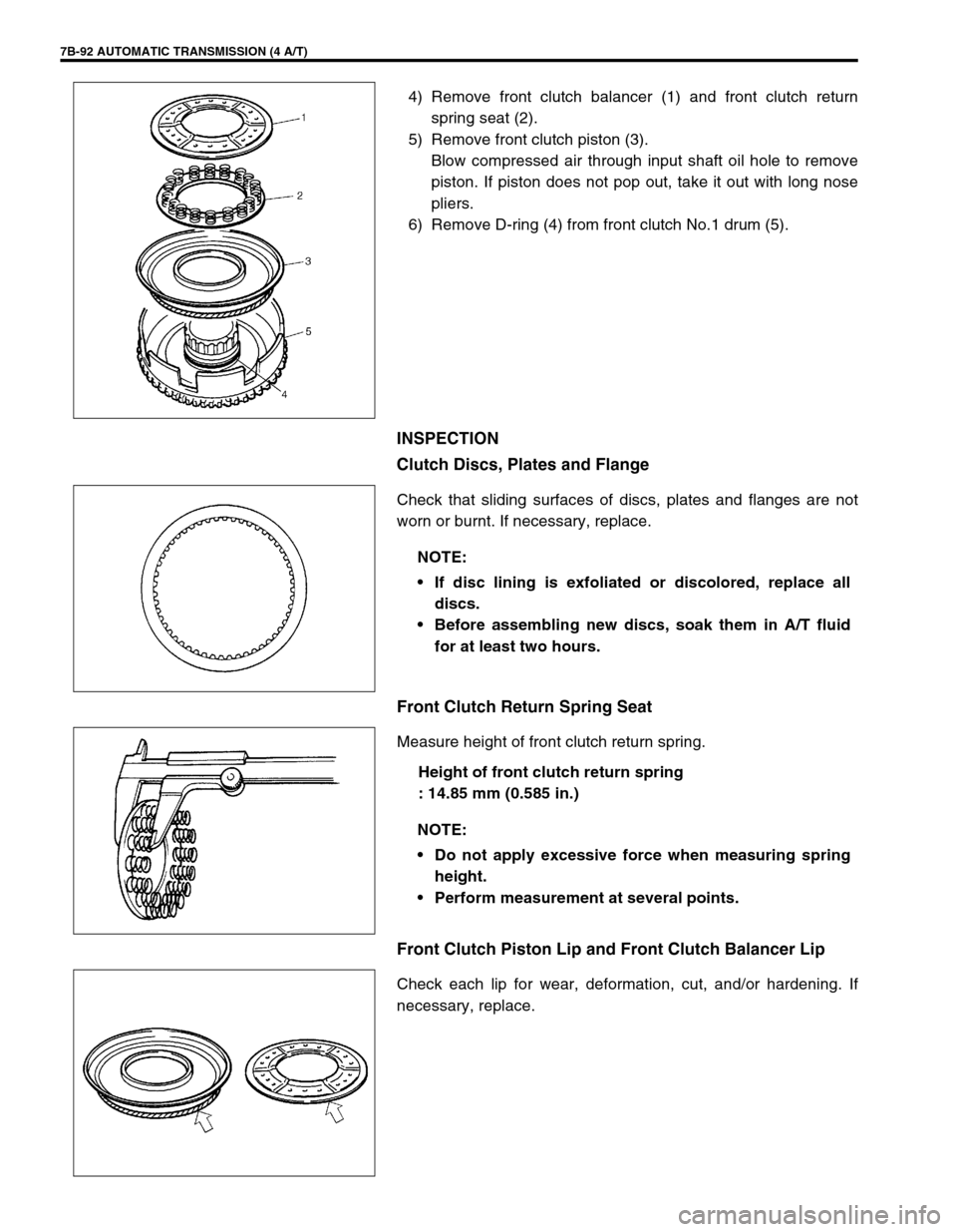
4) Remove front clutch balancer (1) and front clutch return
spring seat (2).
5) Remove front clutch piston (3).
Blow compressed air through input shaft oil hole to remove
piston. If piston does not pop out, take it out with long nose
pliers.
6) Remove D-ring (4) from front clutch No.1 drum (5).
INSPECTION
Clutch Discs, Plates and Flange
Check that sliding surfaces of discs, plates and flanges are not
worn or burnt. If necessary, replace.
Front Clutch Return Spring Seat
Measure height of front clutch return spring.
Height of front clutch return spring
: 14.85 mm (0.585 in.)
Front Clutch Piston Lip and Front Clutch Balancer Lip
Check each lip for wear, deformation, cut, and/or hardening. If
necessary, replace.
NOTE:
If disc lining is exfoliated or discolored, replace all
discs.
Before assembling new discs, soak them in A/T fluid
for at least two hours.
NOTE:
Do not apply excessive force when measuring spring
height.
Perform measurement at several points.