2000 SUZUKI SWIFT brake
[x] Cancel search: brakePage 61 of 447

AUTOMATIC TRANSMISSION (4 A/T) 7B-19
TABLE 2 (MECHANICAL)
Condition Possible Cause Correction
Vehicle does not move
at any rangeManual valve faulty Clean or replace.
Primary regulator valve faulty Clean or replace.
No gear
change
1st
↔
↔↔ ↔ 2nd
Shift solenoid -D (No.4) and/or -E (No.5)
stuck Clean or replace.
2nd
↔
↔↔ ↔ 3rd
Shift solenoid -A (No.1), -C (No.3) and/or fail
valve No.1 stuckClean or replace.
3rd
↔
↔↔ ↔ 4th
Shift solenoid -B (No.2), -C (No.3) and/or fail
valve No.2 stuckClean or replace.
Harsh engagement
P, N
→
→→ → R
Front clutch accumulator faulty Clean or replace.
N
→
→→ → D
1st & 2nd brake accumulator faulty Clean or replace.
1st
→
→→ → 2nd at D
range or 2 rangeFront clutch accumulator faulty Clean or replace.
Shift solenoid -D (No.4) Clean or replace.
2nd
→
→→ → 3rd at D
rangeDirect clutch accumulator faulty Clean or replace.
Shift solenoid -E (No.5) Clean or replace.
3rd
→
→→ → 4th at D
rangeOverdrive brake accumulator faulty Clean or replace.
Shift solenoid -B (No.2) Clean or replace.
All gear change
Primary regulator valve faulty Clean or replace.
Excessive slip
(low line pressure)Primary regulator valve faulty Clean or replace.
Vehicle does not
move at
1st, 2nd, 3rd and
reverse gearRear clutch faulty Repair or replace.
Reverse gear
Reverse brake faulty Repair or replace.
2nd, 3rd and 4th
gearFront clutch faulty Repair or replace.
3rd and 4th gear
Direct clutch faulty Repair or replace.
1st and 2nd gear
1st & 2nd brake faulty Repair or replace.
4th gear
Overdrive brake faulty Repair or replace.
Any forward and
reverse gearParking lock pawl faulty Repair or replace.
Shock or engine stalls
when starting off and
stoppingTCC (lock-up clutch) faulty Inspect and replace as necessary.
TCC (lock-up) solenoid faulty Clean or replace.
Lock-up control valve faulty Clean or replace.
Lock-up signal valve faulty Clean or replace.
No up-shift
1st
→
→→ → 2nd
Front clutch faulty Repair or replace.
2nd
→
→→ → 3rd
Direct clutch faulty Repair or replace.
3rd
→
→→ → 4th
Overdrive brake faulty Repair or replace.
No engine
braking
2nd or 3rd gear
Front, rear or direct clutch or 1st & 2nd brake
faultyRepair or replace
L range 1st gear
Direct clutch or 1st & 2nd brake faulty Repair or replace.
No lock-up
Torque converter clutch faulty Inspect and replace as necessary.
Lock-up control valve faulty Clean or replace.
TCC (lock-up) solenoid faulty Clean or replace.
Secondary regulator valve faulty Clean or replace.
Signal valve faulty Clean or replace.
Page 62 of 447

7B-20 AUTOMATIC TRANSMISSION (4 A/T)
STALL TEST
This test is to check overall performance of automatic transmis-
sion and engine by measuring stall speed at “D” and “R” ranges.
Be sure to perform this test only when transmission fluid is at nor-
mal operating temperature and its level is between FULL and
LOW marks.
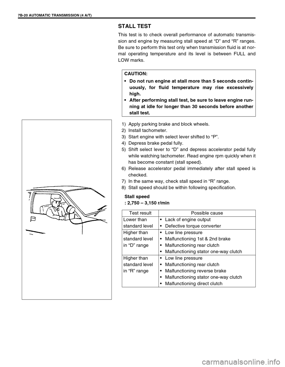
1) Apply parking brake and block wheels.
2) Install tachometer.
3) Start engine with select lever shifted to “P”.
4) Depress brake pedal fully.
5) Shift select lever to “D” and depress accelerator pedal fully
while watching tachometer. Read engine rpm quickly when it
has become constant (stall speed).
6) Release accelerator pedal immediately after stall speed is
checked.
7) In the same way, check stall speed in “R” range.
8) Stall speed should be within following specification.
Stall speed
: 2,750 – 3,150 r/min CAUTION:
Do not run engine at stall more than 5 seconds contin-
uously, for fluid temperature may rise excessively
high.
After performing stall test, be sure to leave engine run-
ning at idle for longer than 30 seconds before another
stall test.
Test result Possible cause
Lower than
standard levelLack of engine output
Defective torque converter
Higher than
standard level
in “D” rangeLow line pressure
Malfunctioning 1st & 2nd brake
Malfunctioning rear clutch
Malfunctioning stator one-way clutch
Higher than
standard level
in “R” rangeLow line pressure
Malfunctioning rear clutch
Malfunctioning reverse brake
Malfunctioning stator one-way clutch
Malfunctioning direct clutch
Page 63 of 447

AUTOMATIC TRANSMISSION (4 A/T) 7B-21
TIME LAG TEST
This test is to check conditions of clutch, reverse brake and fluid
pressure. “Time lag” means time elapsed since select lever is
shifted with engine idling till shock is felt.
1) With chocks placed in front and behind front and rear wheels
respectively, depress brake pedal.
2) Start engine.
3) With stop watch ready, shift select lever from “N” to “D”
range and measure time from that moment till shock is felt.
4) Similarly measure time lag by shifting select lever from “N” to
“R” range.
Specification for time lag
“N”
→
→ → → “D” : Less than 1.0 sec.
“N”
→
→→ → “R” : Less than 1.2 sec.
NOTE:
Make sure that selector cable is properly adjusted.
When repeating this test, be sure to wait at least
minute after select lever is shifted back to “N” range.
Engine should be warmed up fully for this test.
Test result Possible cause
When “N” →
“D”
time lag exceeds specification.Low line pressure
Worn rear clutch
Worn 1st & 2nd brake
When “N” →
“R”
time lag exceeds specification.Low line pressure
Worn rear clutch
Worn direct clutch
Worn reverse brake
Page 64 of 447

7B-22 AUTOMATIC TRANSMISSION (4 A/T)
LINE PRESSURE TEST
Purpose of this test is to check operating conditions of each part
by measuring fluid pressure in fluid pressure line.
Line pressure test requires following conditions.
Automatic fluid is at normal operating temperature (70 –
80°C /158 – 176°F).
Fluid is filled to proper level (between FULL and LOW on
dipstick).
1) Apply parking brake securely and place chocks against
wheels.
2) Remove fluid pressure check hole plug bolt.
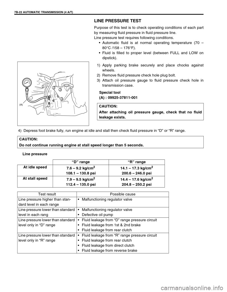
3) Attach oil pressure gauge to fluid pressure check hole in
transmission case.
Special tool
(A) : 09925-37811-001
4) Depress foot brake fully, run engine at idle and stall then check fluid pressure in “D” or “R” range.
Line pressureCAUTION:
After attaching oil pressure gauge, check that no fluid
leakage exists.
(A)
CAUTION:
Do not continue running engine at stall speed longer than 5 seconds.
“D” range “R” range
At idle speed
7.6 – 9.2 kg/cm
2
108.1 – 130.8 psi14.1 – 17.3 kg/cm
2
200.6 – 246.0 psi
At stall speed
7.9 – 9.5 kg/cm
2
112.4 – 135.0 psi14.4 – 17.6 kg/cm
2
204.8 – 250.2 psi
Test result Possible cause
Line pressure higher than stan-
dard level in each rangeMalfunctioning regulator valve
Line pressure lower than standard
level in each rangMalfunctioning regulator valve
Defective oil pump
Line pressure lower than standard
level only in “D” rangeFluid leakage from “D” range pressure circuit
Fluid leakage from 1st & 2nd brake
Fluid leakage from rear clutch
Line pressure lower than standard
level only in “R” rangeFluid leakage from “R” range pressure circuit
Fluid leakage from rear clutch
Fluid leakage from direct clutch
Fluid leakage from reverse brake
Page 65 of 447

AUTOMATIC TRANSMISSION (4 A/T) 7B-23
ENGINE BRAKE TEST
1) While driving vehicle in 3rd gear of “D” range, shift select lever down to “2” range and check if engine brake
operates.
2) In the same way as in Step 1), check engine brake for operation when select lever is shifted down to “L”
range.
3) Engine brake should operate in above test.
“P” RANGE TEST
1) Stop vehicle on a slope, shift select lever to “P” range and at the same time apply parking brake.
2) After stopping engine, depress brake pedal and release parking brake.
3) Then, release brake pedal gradually and check that vehicle remains stationary.
4) Depress brake pedal and shift select lever to “N” range.
5) Then, release brake pedal gradually and check that vehicle moves.WARNING:
Before test, make sure that there is no vehicle behind so as to pre-
vent rear-end collision.
Test result Possible cause
Fails to operate when shifted down to “2”
rangeDefective shift switch
1st & 2nd brake defective
Direct clutch defective
Fails to operate when shifted down to “L”
range
WARNING:
Before test, check to make sure no one is around vehicle or
down on a slope and keep watchful for safety during test.
Test result Possible cause
Vehicle moves at “P” range or
remains stationary at “N” rangeDefective parking lock pawl or
spring
Page 96 of 447

7B-54 AUTOMATIC TRANSMISSION (4 A/T)
C4312Serial data link (SUZUKI scan
tool)10 – 14 V IG switch ON
13Output shaft speed sensor
shield––
14 Output shaft speed sensor(–)––
15 Input shaft speed sensor(–)––
C442 IG power source 10 – 14 V IG switch ON
3Transmission temperature
sensor0 – 4.5 V IG switch ON
4 Brake switch 10 – 14 V IG switch ON, brake pedal depressed
5 A/C compressor0 – 2 V A/C OFF
10 – 14 V A/C ON
8 Idle up signal10 – 14 V Selector lever at “P” or “N” range
0 – 1 V Selector lever other than “P” or “N” range
10 Shift solenoid-A (No.1) 0 – 1 V IG switch ON, select lever at “P” range
11Shift solenoid-C (Dropping
resistor)0 – 1 V IG switch ON, select lever at “P” range
12Shift solenoid-D (Dropping
resistor)10 – 14 V IG switch ON, select lever at “P” range
13Shift solenoid-E (Dropping
resistor)0 – 1 V IG switch ON, select lever at “P” range
15 Ground––
16Transmission temperature
sensor ground––
17 O/D off switch0 – 1 V IG switch ON, O/D off switch ON
10 – 14 V IG switch ON, O/D off switch OFF
18Engine coolant temperature/
Barometric pressure signal––
20 A/T failure serial data 0 – 1 V IG switch ON
21 O/D OFF lamp10 – 14 V IG switch ON, O/D off switch OFF
0 – 1 V IG switch ON, O/D off switch ON
22 Lock-up solenoid 0 – 1 V IG switch ON, selector lever at “P” range
23 Shift solenoid-B (No.2) 0 – 1 V IG switch ON, selector lever at “P” range
24 Shift solenoid-C (No.3) 0 – 1 V IG switch ON, selector lever at “P” range
25 Shift solenoid-D (No.4) 2.2 – 4.9 V IG switch ON, selector lever at “P” range
26 Shift solenoid-E (No.5) 0 – 1 V IG switch ON, selector lever at “P” range TERMINAL CIRCUITSTAN-
DARD
VOLTAGECONDITION
Page 97 of 447

AUTOMATIC TRANSMISSION (4 A/T) 7B-55
ON-VEHICLE SERVICE
MAINTENANCE SERVICE
FLUID LEVEL AT NORMAL OPERATING TEMPERA-
TURE
INSPECTION
1) Stop vehicle and place it level.
2) Apply parking brake and place chocks against wheels.
3) With selector at P position, start engine.
4) Warm up engine till fluid temperature reaches normal oper-
ating temperature (70 – 80°C/158 – 176°F). As a guide to
check fluid temperature, warm up engine to normal operat-
ing temperature.
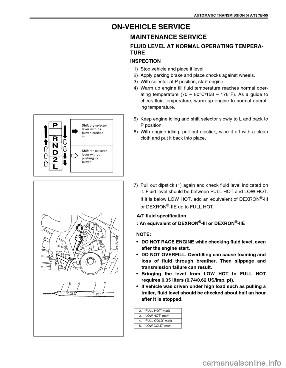
5) Keep engine idling and shift selector slowly to L and back to
P position.
6) With engine idling, pull out dipstick, wipe it off with a clean
cloth and put it back into place.
7) Pull out dipstick (1) again and check fluid level indicated on
it. Fluid level should be between FULL HOT and LOW HOT.
If it is below LOW HOT, add an equivalent of DEXRON
®-III
or DEXRON
®-IIE up to FULL HOT.
A/T fluid specification
: An equivalent of DEXRON
®-III or DEXRON®-IIE
NOTE:
DO NOT RACE ENGINE while checking fluid level, even
after the engine start.
DO NOT OVERFILL. Overfilling can cause foaming and
loss of fluid through breather. Then slippage and
transmission failure can result.
Bringing the level from LOW HOT to FULL HOT
requires 0.35 liters (0.74/0.62 US/Imp. pt).
If vehicle was driven under high load such as pulling a
trailer, fluid level should be checked about half an hour
after it is stopped.
2.“FULL HOT” mark
3.“LOW HOT” mark
4.“FULL COLD” mark
5.“LOW COLD” mark
1
Page 102 of 447

7B-60 AUTOMATIC TRANSMISSION (4 A/T)
SELECTOR CABLE
REMOVAL
1) Remove parking brake lever cover.
2) Remove console box.
3) Disconnect selector cable from selector lever and then
detach from bracket.
4) Remove clip and disconnect selector cable from transmis-
sion.
5) Remove selector housing from dash panel.
INSTALLATION
Install selector cable by reversing removal procedure.
The important steps in installation are as follows.
Apply grease to pin and cable joint.
Tighten bolts and nut in upper figure to specified torque.
Adjusting procedure is as follows.
1. Selector lever assembly 6. Clip
2. Selector cable 7. Selector housing bolt
3. Selector housing 8. Shift control lever pin
: Apply lithium grease 99000-25010 to all around pin (0.15 g)
4. Cable bracket 9. Selector lever pin
: Apply lithium grease 99000-25010 to all around pin (0.15 g)
5. Shift control lever Tightening torque