Page 361 of 557

6A1-66 ENGINE MECHANICAL (G13B, 1-CAM 16-VALVES ENGINE)
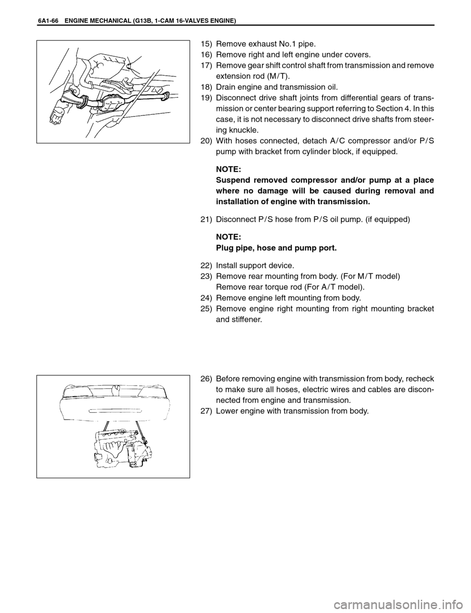
15) Remove exhaust No.1 pipe.
16) Remove right and left engine under covers.
17) Remove gear shift control shaft from transmission and remove
extension rod (M / T).
18) Drain engine and transmission oil.
19) Disconnect drive shaft joints from differential gears of trans-
mission or center bearing support referring to Section 4. In this
case, it is not necessary to disconnect drive shafts from steer-
ing knuckle.
20) With hoses connected, detach A / C compressor and/or P / S
pump with bracket from cylinder block, if equipped.
NOTE:
Suspend removed compressor and/or pump at a place
where no damage will be caused during removal and
installation of engine with transmission.
21) Disconnect P / S hose from P / S oil pump. (if equipped)
NOTE:
Plug pipe, hose and pump port.
22) Install support device.
23) Remove rear mounting from body. (For M / T model)
Remove rear torque rod (For A / T model).
24) Remove engine left mounting from body.
25) Remove engine right mounting from right mounting bracket
and stiffener.
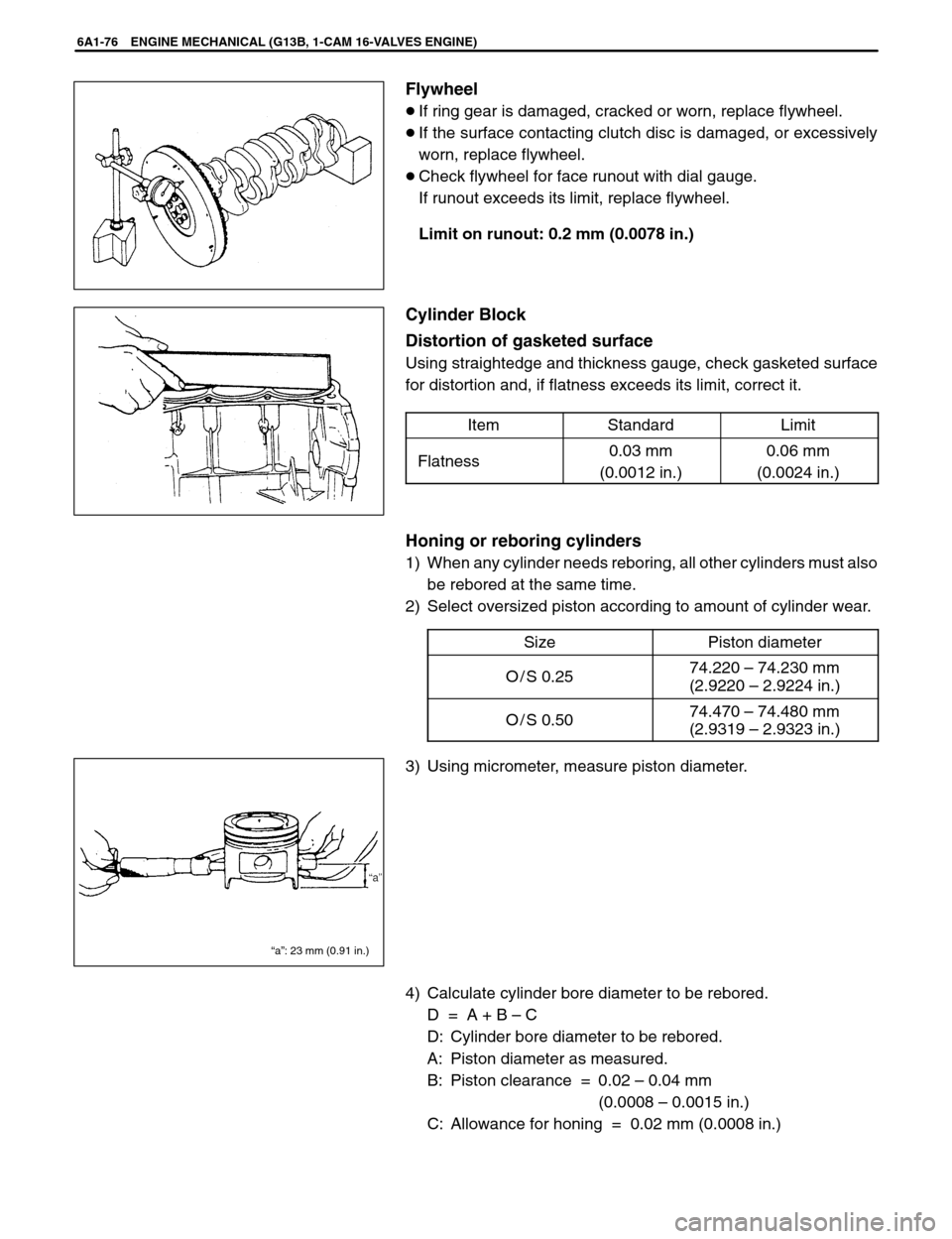
26) Before removing engine with transmission from body, recheck
to make sure all hoses, electric wires and cables are discon-
nected from engine and transmission.
27) Lower engine with transmission from body.
Page 364 of 557
1. Flywheel bolt
2. Bolt
ENGINE MECHANICAL (G13B, 1-CAM 16-VALVES ENGINE) 6A1-69
REMOVAL
1) Remove engine assembly from body as previously outlined.
2) Remove clutch cover, clutch disc and flywheel (drive plate for
A / T).
Special Tool
(A): 09924-17810
3) Remove crankshaft pulley, timing belt and crankshaft timing
pulley.
4) Remove cylinder head assembly.
5) Remove oil pan and oil pump strainer.
6) Remove oil pump (1).
7) Remove oil seal housing.
8) Remove connecting rod bearing caps.
9) Loosen crankshaft bearing cap bolts in such order as indicated
in figure a little at a time and remove bearing caps.
10) Remove crankshaft from cylinder block.
Page 371 of 557

“a”: 23 mm (0.91 in.)
6A1-76 ENGINE MECHANICAL (G13B, 1-CAM 16-VALVES ENGINE)
Flywheel
�If ring gear is damaged, cracked or worn, replace flywheel.
�If the surface contacting clutch disc is damaged, or excessively
worn, replace flywheel.
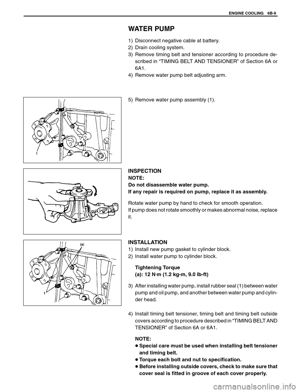
�Check flywheel for face runout with dial gauge.
If runout exceeds its limit, replace flywheel.
Limit on runout: 0.2 mm (0.0078 in.)
Cylinder Block
Distortion of gasketed surface
Using straightedge and thickness gauge, check gasketed surface
for distortion and, if flatness exceeds its limit, correct it.
Item
StandardLimit
Flatness0.03 mm
(0.0012 in.)0.06 mm
(0.0024 in.)
Honing or reboring cylinders
1) When any cylinder needs reboring, all other cylinders must also
be rebored at the same time.
2) Select oversized piston according to amount of cylinder wear.
Size
Piston diameter
O / S 0.2574.220 – 74.230 mm
(2.9220 – 2.9224 in.)
O / S 0.5074.470 – 74.480 mm
(2.9319 – 2.9323 in.)
3) Using micrometer, measure piston diameter.
4) Calculate cylinder bore diameter to be rebored.
D = A + B – C
D: Cylinder bore diameter to be rebored.
A: Piston diameter as measured.
B: Piston clearance = 0.02 – 0.04 mm
(0.0008 – 0.0015 in.)
C: Allowance for honing = 0.02 mm (0.0008 in.)
Page 379 of 557
8. Heater inlet hose
9. Heater outlet hose
10. Radiator
11. Oil cooler (A / T only)
12. Engine
13. ECT sensor1. Radiator inlet hose
2. Radiator outlet hose
3. Water intake pipe
4. Thermostat
5. Water pump
6. IAC valve (throttle body)
7. Breather pipe (air cleaner
outlet hose)
6B-2 ENGINE COOLING
GENERAL DESCRIPTION
COOLING SYSTEM CIRCULATION
During engine warm-up (thermostat closed), the water pump discharges coolant into the water jacket chamber
adjacent to No.1 cylinder. Coolant then flows through the cylinder block and the cylinder heat. Coolant then returns
to the water pump through intake manifold, heater inlet hose, heater unit, heater outlet hose, and water intake pipe.
During normal temperatures (thermostat open), coolant takes the same basic route but is now allowed to flow past
the thermostat, the inlet hose and the radiator, and then back to the water pump through the outlet hose and the
water intake pipe.
Page 383 of 557

2. Outlet hose
6B-6 ENGINE COOLING
COOLING SYSTEM FLUSH AND REFILL
WARNING:
To help avoid danger of being burned, do not remove radia-
tor cap while engine and radiator cap while engine and ra-
diator are still hot. Scalding fluid and steam can be blown
out under pressure if cap is taken off too soon.
1) Remove radiator cap when engine is cool:
Turn cap counterclockwise slowly until it reaches a “stop”.
(Do not press down while turning it.)
Wait until pressure is relieved (indicated by a hissing sound)
then press down on cap and continue to turn it counterclock-
wise.
2) With radiator cap removed, run engine until upper radiator
hose is hot (this shows that thermostat is open and coolant is
flowing through system).
3) Stop engine and open radiator drain plug (1) to drain coolant.
4) Close drain plug. Add water until system is filled and run engine
until upper radiator hose is hot again.
5) Repeat Steps 3) and 4) several times until drained liquid is
nearly colorless.
6) Drain system and then close radiator drain plug tightly.
7) Disconnect reservoir tank hose from radiator. Remove reser-
voir tank and pour out any fluid. Scrub and clean inside of tank
with soap and water.
Flush it well with clean water and drain. Reinstall tank and
hose.
8) add 50 / 50 mixture of GOLDEN CRUISER 1200 (Good quality
ethylene glycol anti-freeze) and water to radiator and tank.
Fill radiator to the base of radiator filler neck and reservoir tank
to “FULL” level mark. Reinstall reservoir tank cap.
9) Run engine, with radiator cap removed, until radiator upper
hose is hot.
10) With engine idling, add coolant to radiator until level reaches
the bottom of filler neck. Install radiator cap, making sure that
the ear of cap lines up with reservoir tank hose.
Page 384 of 557
1. Radiator hose
2. Clamp
ENGINE COOLING 6B-7
ON-VEHICLE SERVICE
WARNING:
�Check to make sure that engine coolant temperature is
cold before removing any part of cooling system.
�Also be sure to disconnect negative cord from battery ter-
minal before removing any part.
COOLING WATER PIPES OR HOSES
REMOVAL
1) Drain cooling system.
2) To remove these pipes or hoses, loosen screw on each pipe or
hose clip and pull hose end off.
INSTALLATION
Install removed parts in reverse order of removal procedure, noting
the following.
�Tighten each clamp bolt securely.
�Refill cooling system with proper coolant, referring to description
on COOLANT of MAINTENANCE.
THERMOSTAT
REMOVAL
1) Disconnect negative cable at battery.
2) Drain cooling system and tighten drain plug.
3) Disconnect thermostat cap (1) from thermostat case (2).
Page 386 of 557

ENGINE COOLING 6B-9
WATER PUMP
1) Disconnect negative cable at battery.
2) Drain cooling system.
3) Remove timing belt and tensioner according to procedure de-
scribed in “TIMING BELT AND TENSIONER” of Section 6A or
6A1.
4) Remove water pump belt adjusting arm.
5) Remove water pump assembly (1).
INSPECTION
NOTE:
Do not disassemble water pump.
If any repair is required on pump, replace it as assembly.
Rotate water pump by hand to check for smooth operation.
If pump does not rotate smoothly or makes abnormal noise, replace
it.
INSTALLATION
1) Install new pump gasket to cylinder block.
2) Install water pump to cylinder block.
Tightening Torque
(a): 12 N
.m (1.2 kg-m, 9.0 lb-ft)
3) After installing water pump, install rubber seal (1) between water
pump and oil pump, and another between water pump and cylin-
der head.
4) Install timing belt tensioner, timing belt and timing belt outside
covers according to procedure described in “TIMING BELT AND
TENSIONER” of Section 6A or 6A1.
NOTE:
�Special care must be used when installing belt tensioner
and timing belt.
�Torque each bolt and nut to specification.
�Before installing outside covers, check to make sure that
cover seal is fitted in groove of each cover properly.
Page 389 of 557
1. Fuel tank
2. Fuel pump and level gauge
3. Fuel filler cap
4. 2-way check valve
5. Breather hose
6. Fuel feed line
7. Fuel return line
8. Fuel vapor line
9. Fuel cut valve
10. Fuel tank pad
11. Fuel tank fixer bolt
: Tightening Torque
6C-2 ENGINE FUEL
ON-VEHICLE SERVICE
FUEL LINES
INSPECTION
Visually inspect fuel lines for evidence of fuel leakage, hose crack
and deterioration, or damage.
Make sure all clamps are secure.
Replace parts as needed.
FUEL TANK
REMOVAL
1) Relieve fuel pressure in fuel feed line according to procedure de-
scribed in Section 6.
2) Disconnect negative cable at battery.
3) Remove rear seat cushion referring to Section 9.
4) Disconnect connectors (1) of fuel tank wire harness.
5) Hoist vehicle.
6) Disconnect fuel filler hose (3) from fuel tank and breather hose
(2) from filler neck (1).