2000 SUZUKI SWIFT Rpm
[x] Cancel search: RpmPage 72 of 698

AIR CONDITIONING (OPTIONAL) 1B-7
ABNORMAL NOISE DIAGNOSIS
There are various types of noise, ranging from those produced in the engine compartment to those from the
passenger compartment, also from rumbling noises to whistling noises.
ABNORMAL NOISE FROM COMPRESSOR
ABNORMAL NOISE FROM MAGNETIC CLUTCH
ABNORMAL NOISE FROM TUBING
ABNORMAL NOISE FROM CONDENSER
Condition Possible Cause Correction
During compressor
operation, a rumbling
noise is heard propor-
tional to engine
revolutions.Inadequate clearance in piston area (piston or
swash-plate)Repair or replace compressor as
necessary.
A loud noise is heard
at a certain rpm, dis-
proportionately to
engine revolution.Loose or faulty compressor drive belt Adjust drive belt tension, or replace
drive belt.
Loose compressor mounting bolts Retighten mounting bolts.
A loud rattle is heard
at low engine rpm.Loose compressor clutch plate bolt Retighten clutch plate bolt.
Replace compressor if it was oper-
ated in this condition for a long
time.
Condition Possible Cause Correction
A rumbling noise is
heard when compres-
sor is not operating.Worn or damaged bearings Replace magnet clutch assembly.
A chattering noise is
heard when compres-
sor is engaged.Faulty clutch clearance (excessive) Adjust clutch clearance.
Worn clutch friction surface Replace magnet clutch assembly.
Compressor oil leaked from lip type seal, con-
taminating the friction surfaceReplace compressor body assem-
bly.
Condition Possible Cause Correction
A droning noise is
heard inside vehicle,
but not particularly
noticeable in engine
compartment.Faulty tubing clamps Reposition clamps or increase the
number of clamps.
Resonance caused by pulsation from variations
in refrigerant pressureAttach a silencer to tubing, or mod-
ify its position and length.
Condition Possible Cause Correction
Considerable vibra-
tion in condenser.Resonance from condenser bracket and body Firmly insert a silencer between
condenser bracket and body.
Page 73 of 698

1B-8 AIR CONDITIONING (OPTIONAL)
ABNORMAL NOISE FROM CRANKSHAFT PULLEY
ABNORMAL NOISE FROM TENSION PULLEY
ABNORMAL NOISE FROM A/C EVAPORATOR
ABNORMAL NOISE FROM BLOWER FAN MOTOR
Condition Possible Cause Correction
A large rattling noise
is heard at idle or sud-
den acceleration.Loosen crankshaft pulley bolt Retighten bolt.
Condition Possible Cause Correction
Clattering noise is
heard from pulley.Worn or damaged bearing Replace tension pulley.
Pulley cranks upon
contact.Cracked or loose bracket Replace or retighten bracket.
Condition Possible Cause Correction
Whistling sound is
heard from A/C evapo-
rator.Depending on the combination of the interior/
exterior temperatures, engine rpm and refriger-
ant pressure, the refrigerant flowing out of the
expansion valve may, under certain conditions,
make a whistling soundAt times, slightly decreasing refrig-
erant volume may stop this noise.
Inspect expansion valve and
replace if faulty.
Condition Possible Cause Correction
Blower fan motor
emits a chirping
sound in proportion to
its speed of rotation.Worn or damaged motor brushes or commuta-
torRepair or replace blower fan motor.
Fluttering noise or
large droning noise is
heard from blower fan
motor.Leaves or other debris introduced from fresh air
inlet to blower fan motorRemove debris and make sure that
the screen at fresh air inlet is intact.
Page 75 of 698

1B-10 AIR CONDITIONING (OPTIONAL)
PERFORMANCE DIAGNOSIS
1) Confirm that vehicle and environmental conditions are as fol-
lows.
Vehicle is not exposed to direct sun.
Ambient temperature is within 15 – 35°C (59 – 95°F).
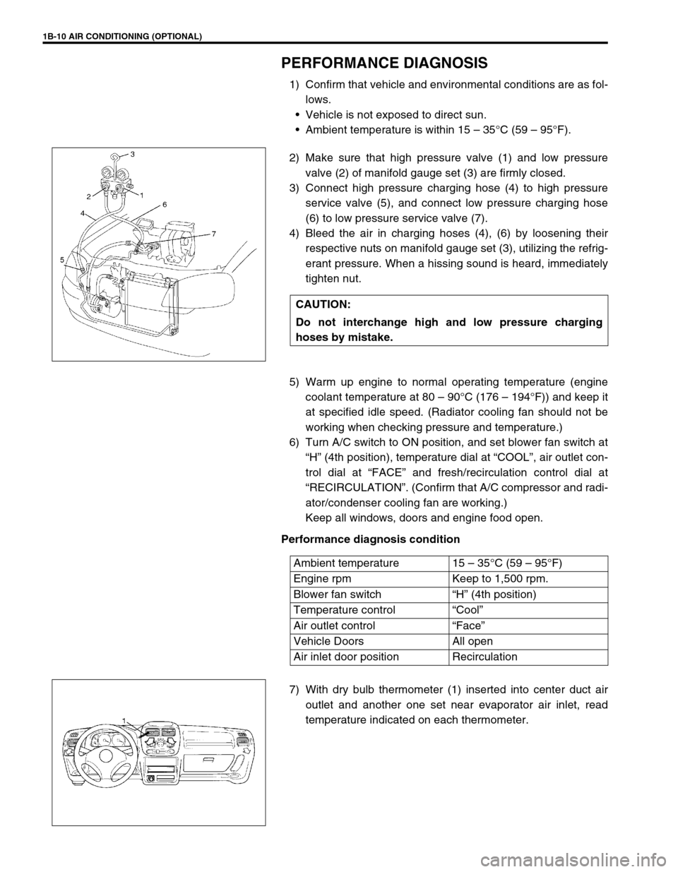
2) Make sure that high pressure valve (1) and low pressure
valve (2) of manifold gauge set (3) are firmly closed.
3) Connect high pressure charging hose (4) to high pressure
service valve (5), and connect low pressure charging hose
(6) to low pressure service valve (7).
4) Bleed the air in charging hoses (4), (6) by loosening their
respective nuts on manifold gauge set (3), utilizing the refrig-
erant pressure. When a hissing sound is heard, immediately
tighten nut.
5) Warm up engine to normal operating temperature (engine
coolant temperature at 80 – 90°C (176 – 194°F)) and keep it
at specified idle speed. (Radiator cooling fan should not be
working when checking pressure and temperature.)
6) Turn A/C switch to ON position, and set blower fan switch at
“H” (4th position), temperature dial at “COOL”, air outlet con-
trol dial at “FACE” and fresh/recirculation control dial at
“RECIRCULATION”. (Confirm that A/C compressor and radi-
ator/condenser cooling fan are working.)
Keep all windows, doors and engine food open.
Performance diagnosis condition
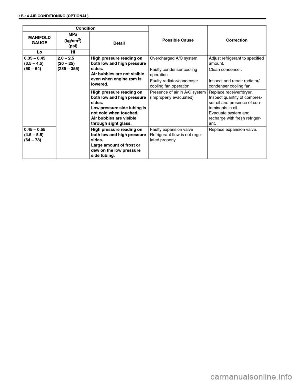
7) With dry bulb thermometer (1) inserted into center duct air
outlet and another one set near evaporator air inlet, read
temperature indicated on each thermometer. CAUTION:
Do not interchange high and low pressure charging
hoses by mistake.
Ambient temperature 15 – 35°C (59 – 95°F)
Engine rpm Keep to 1,500 rpm.
Blower fan switch“H” (4th position)
Temperature control“Cool”
Air outlet control“Face”
Vehicle Doors All open
Air inlet door position Recirculation
Page 79 of 698

1B-14 AIR CONDITIONING (OPTIONAL)
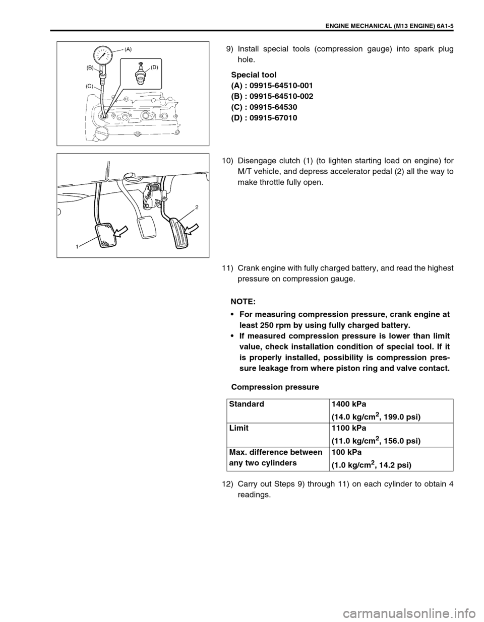
0.35 – 0.45
(3.5 – 4.5)
(50 – 64)2.0 – 2.5
(20 – 25)
(285 – 355)High pressure reading on
both low and high pressure
sides.
Air bubbles are not visible
even when engine rpm is
lowered.Overcharged A/C system Adjust refrigerant to specified
amount.
Faulty condenser cooling
operationClean condenser.
Faulty radiator/condenser
cooling fan operationInspect and repair radiator/
condenser cooling fan.
High pressure reading on
both low and high pressure
sides.
Low pressure side tubing is
not cold when touched.
Air bubbles are visible
through sight glass.Presence of air in A/C system
(Improperly evacuated)Replace receiver/dryer.
Inspect quantity of compres-
sor oil and presence of con-
taminants in oil.
Evacuate system and
recharge with fresh refriger-
ant.
0.45 – 0.55
(4.5 – 5.5)
(64 – 78)High pressure reading on
both low and high pressure
sides.
Large amount of frost or
dew on the low pressure
side tubing.Faulty expansion valve
Refrigerant flow is not regu-
lated properlyReplace expansion valve. Condition
Possible Cause Correction MANIFOLD
GAUGEMPa
(kg/cm
2)
(psi)Detail
Lo Hi
Page 402 of 698

ENGINE GENERAL INFORMATION AND DIAGNOSIS 6-33
SCAN TOOL DATA DEFINITIONS :
FUEL SYSTEM (FUEL SYSTEM STATUS)
Air/fuel ratio feedback loop status displayed as either open or closed loop. Open indicates that ECM ignores
feedback from the exhaust oxygen sensor.
Closed indicates final injection duration is corrected for oxygen sensor feedback.
CALC LOAD (CALCULATED LOAD VALUE, %)
Engine load displayed as a percentage of maximum possible load. Value is calculated mathematically using the
formula : actual (current) intake air volume ÷ maximum possible intake air volume x 100%.
COOLANT TEMP. (ENGINE COOLANT TEMPERATURE, °C, °F)
It is detected by engine coolant temp. sensor
SHORT FT B1 (SHORT TERM FUEL TRIM, %)
Short term fuel trim value represents short term corrections to the air/fuel mixture computation. A value of 0 indi-
cates no correction, a value greater than 0 means an enrichment correction, and a value less than 0 implies an
enleanment correction.
LONG FT B1 (LONG TERM FUEL TRIM, %)
Long term fuel trim Value represents long term corrections to the air/fuel mixture computation. A value of 0 indi-
cates no correction, a value greater than 0 means an enrichment correction, and a value less than 0 implies an
enleanment correction.
MAP (INTAKE MANIFOLD ABSOLUTE PRESSURE, kPa, inHg)
It is detected by manifold absolute pressure sensor and used (among other things) to compute engine load.
ENGINE SPEED (rpm)
It is computed by reference pulses from crankshaft position sensor.
VEHICLE SPEED (km/h, MPH)
It is computed based on pulse signals from vehicle speed sensor.PNP SIGNAL (PARK/NEU-
TRAL POSITION SIGNAL)
A/T onlyIgnition switch
ONSelector lever in “P” or “N”
positionP/N Range
Selector lever in “R”, “D”,
“2” or “L” positionD Range
EGR VALVE At specified idle speed after warming up 0%
∆FUEL TANK LEVEL–0 – 100%
BAROMETRIC PRESS–Display the barometric pres-
sure
FUEL PUMP Within 3 seconds after ignition switch ON or
engine runningON
Engine stop at ignition switch ON. OFF
BRAKE SW Ignition switch
ONBrake pedal is depressing ON
Brake pedal is releasing OFF
BLOWER FAN Ignition switch
ONBlower fan switch ON ON
Blower fan switch OFF OFF
A/C MAG CLUTCH Ignition switch
ONA/C switch ON ON
A/C switch OFF OFF SCAN TOOL DATA VEHICLE CONDITION NORMAL CONDITION/
REFERENCE VALUES
Page 403 of 698

6-34 ENGINE GENERAL INFORMATION AND DIAGNOSIS
IGNITION ADVANCE (IGNITION TIMING ADVANCE FOR NO.1 CYLINDER, °)
Ignition timing of NO.1 cylinder is commanded by ECM. The actual ignition timing should be checked by using
the timing light.
INTAKE AIR TEMP. (°C, °F)
It is detected by intake air temp. sensor and used to determine the amount of air passing into the intake manifold
as air density varies with temperature.
MAF (MASS AIR FLOW RATE, gm/s, lb/min)
It represents total mass of air entering intake manifold which is computed based on signals from MAP sensor,
IAT sensor, TP sensor, etc.
THROTTLE POS (ABSOLUTE THROTTLE POSITION, %)
When throttle position sensor is fully closed position, throttle opening is indicated as 0% and 100% full open
position.
OXYGEN SENSOR B1 S1 (HEATED OXYGEN SENSOR-1, V)
It indicates output voltage of HO2S-1 installed on exhaust manifold (pre-catalyst).
OXYGEN SENSOR B1 S2 (HEATED OXYGEN SENSOR-2, V)
It indicates output voltage of HO2S-2 installed on exhaust pipe (post-catalyst). It is used to detect catalyst dete-
rioration.
DESIRED IDLE (DESIRED IDLE SPEED, rpm)
The Desired Idle Speed is an ECM internal parameter which indicates the ECM requested idle. If the engine is
not running, this number is not valid.
TP SENSOR VOLT (THROTTLE POSITION SENSOR OUTPUT VOLTAGE, V)
The Throttle Position Sensor reading provides throttle valve opening information in the form of voltage.
INJ PULSE WIDTH (FUEL INJECTION PULSE WIDTH, msec.)
This parameter indicates time of the injector drive (valve opening) pulse which is output from ECM (but injector
drive time of NO.1 cylinder for multiport fuel injection).
IAC FLOW DUTY (IDLE AIR (SPEED) CONTROL DUTY, %)
This parameter indicates current flow time rate within a certain set cycle of IAC valve (valve opening rate) which
controls the amount of bypass air (idle speed).
TOTAL FUEL TRIM (%)
The value of Total Fuel Trim is obtained by putting values of short Term Fuel Trim and Long Term Fuel Trim
together. This value indicates how much correction is necessary to keep the air/fuel mixture stoichiometrical.
BATTERY VOLTAGE (V)
This parameter indicates battery positive voltage inputted from main relay to ECM.
CANIST PURGE DUTY (EVAP CANISTER PURGE FLOW DUTY, %)
This parameter indicates valve ON (valve open) time rate within a certain set cycle of EVAP purge solenoid
valve which controls the amount of EVAP purge.
0% means that the purge valve is completely closed while 100% is a fully open valve.
CLOSED THROTTLE POSITION (ON/OFF)
This parameter will read ON when throttle valve is fully closed, or OFF when the throttle is not fully closed.
FUEL CUT (ON/OFF)
ON : Fuel being cut (output signal to injector is stopped)
OFF : Fuel not being cut
Page 506 of 698

ENGINE MECHANICAL (M13 ENGINE) 6A1-5
9) Install special tools (compression gauge) into spark plug
hole.
Special tool
(A) : 09915-64510-001
(B) : 09915-64510-002
(C) : 09915-64530
(D) : 09915-67010
10) Disengage clutch (1) (to lighten starting load on engine) for
M/T vehicle, and depress accelerator pedal (2) all the way to
make throttle fully open.
11) Crank engine with fully charged battery, and read the highest
pressure on compression gauge.
Compression pressure
12) Carry out Steps 9) through 11) on each cylinder to obtain 4
readings.
NOTE:
For measuring compression pressure, crank engine at
least 250 rpm by using fully charged battery.
If measured compression pressure is lower than limit
value, check installation condition of special tool. If it
is properly installed, possibility is compression pres-
sure leakage from where piston ring and valve contact.
Standard 1400 kPa
(14.0 kg/cm
2, 199.0 psi)
Limit 1100 kPa
(11.0 kg/cm
2, 156.0 psi)
Max. difference between
any two cylinders100 kPa
(1.0 kg/cm
2, 14.2 psi)
Page 509 of 698

6A1-8 ENGINE MECHANICAL (M13 ENGINE)
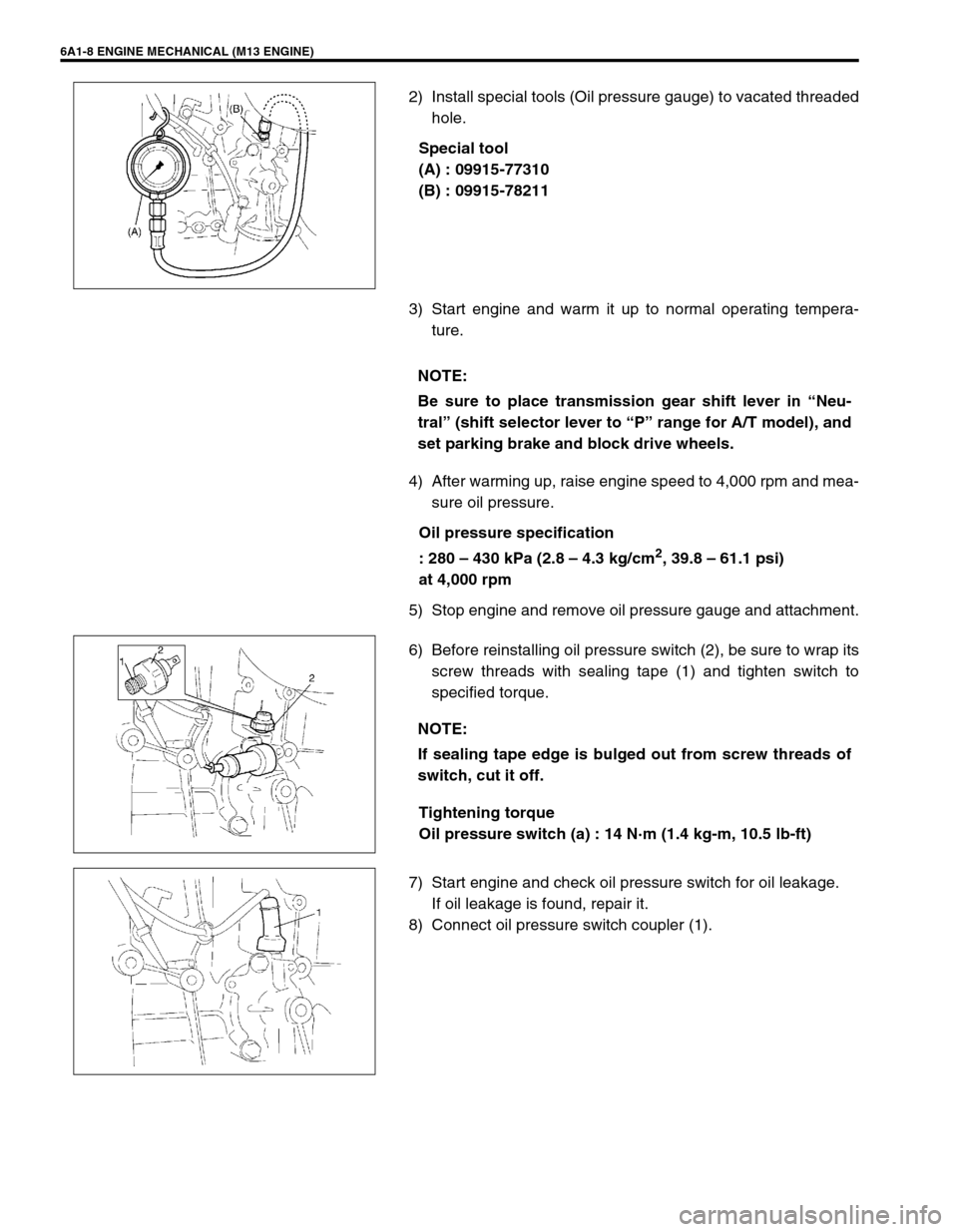
2) Install special tools (Oil pressure gauge) to vacated threaded
hole.
Special tool
(A) : 09915-77310
(B) : 09915-78211
3) Start engine and warm it up to normal operating tempera-
ture.
4) After warming up, raise engine speed to 4,000 rpm and mea-
sure oil pressure.
Oil pressure specification
: 280 – 430 kPa (2.8 – 4.3 kg/cm
2, 39.8 – 61.1 psi)
at 4,000 rpm
5) Stop engine and remove oil pressure gauge and attachment.
6) Before reinstalling oil pressure switch (2), be sure to wrap its
screw threads with sealing tape (1) and tighten switch to
specified torque.
Tightening torque
Oil pressure switch (a) : 14 N·m (1.4 kg-m, 10.5 lb-ft)
7) Start engine and check oil pressure switch for oil leakage.
If oil leakage is found, repair it.
8) Connect oil pressure switch coupler (1).
NOTE:
Be sure to place transmission gear shift lever in “Neu-
tral” (shift selector lever to “P” range for A/T model), and
set parking brake and block drive wheels.
NOTE:
If sealing tape edge is bulged out from screw threads of
switch, cut it off.