2000 SUZUKI SWIFT steering wheel
[x] Cancel search: steering wheelPage 251 of 698
3F-6 WHEELS AND TIRES
INFLATION OF TIRES
The pressure recommended for any model is carefully calculated to give a satisfactory ride, stability, steering,
tread wear, tire life and resistance to bruises.
Tire pressure, with tires cold, (after vehicle has set for 3 hours or more, or driven less than one mile) should be
checked monthly or before any extended trip. Set to the specifications on the “Tire Placard” located on the left
door (right door for right-hand side steering vehicle) lock pillar.
It is normal for tire pressure to increase when the tires become hot during driving.
Do not bleed or reduce tire pressure after driving. Bleeding reduces the “Cold Inflation Pressure”.
Higher than recommended pressure can cause :
Hard ride
Tire bruising or carcass damage
Rapid tread wear at center of tire
Unequal pressure on same axle can cause :
Uneven braking
Steering lead
Reduced handling
Swerve on acceleration
Lower than recommended pressure can cause :
Tire squeal on turns
Hard Steering
Rapid and uneven wear on the edges of the tread
Tire rim bruises and rupture
Tire cord breakage
High tire temperature
Reduced handling
High fuel consumption
TIRE ROTATION
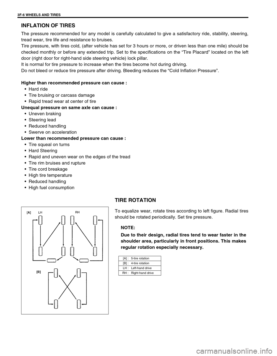
To equalize wear, rotate tires according to left figure. Radial tires
should be rotated periodically. Set tire pressure.
NOTE:
Due to their design, radial tires tend to wear faster in the
shoulder area, particularly in front positions. This makes
regular rotation especially necessary.
[A] : 5-tire rotation
[B] : 4-tire rotation
LH : Left-hand drive
RH : Right-hand drive
Page 257 of 698
4A-4 FRONT DRIVE SHAFT
DRIVE SHAFT ASSEMBLY
REMOVAL
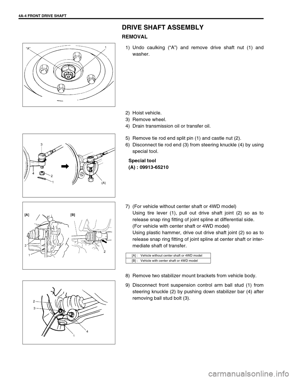
1) Undo caulking (“A”) and remove drive shaft nut (1) and
washer.
2) Hoist vehicle.
3) Remove wheel.
4) Drain transmission oil or transfer oil.
5) Remove tie rod end split pin (1) and castle nut (2).
6) Disconnect tie rod end (3) from steering knuckle (4) by using
special tool.
Special tool
(A) : 09913-65210
7) (For vehicle without center shaft or 4WD model)
Using tire lever (1), pull out drive shaft joint (2) so as to
release snap ring fitting of joint spline at differential side.
(For vehicle with center shaft or 4WD model)
Using plastic hammer, drive out drive shaft joint (2) so as to
release snap ring fitting of joint spline at center shaft or inter-
mediate shaft of transfer.
8) Remove two stabilizer mount brackets from vehicle body.
9) Disconnect front suspension control arm ball stud (1) from
steering knuckle (2) by pushing down stabilizer bar (4) after
removing ball stud bolt (3).
[A] : Vehicle without center shaft or 4WD model
[B] : Vehicle with center shaft or 4WD model
Page 279 of 698
5-6 BRAKES
Excessive pedal travel
(Pedal stroke too
large)Partial brake system failure Check brake systems and repair as
necessary.
Insufficient fluid in master cylinder reservoirs Fill reservoirs with approved brake
fluid.
Check for leaks and air in brake
system.
Check warning light. Bleed system
if required.
Air in system (soft/spongy pedal) Bleed system.
Rear brake system not adjusted
(malfunctioning auto adjusting mechanism)Repair auto adjusting mechanism.
Adjust rear brakes.
Bent brake shoes Replace brake shoes.
Worn rear brake shoes Replace brake shoes.
Brake locked
(For vehicle equipped
with ABS)Malfunctioning ABS Check system referring to Section
5E1.
Dragging brakes
(A very light drag is
present in all brakes
immediately after
pedal is released)Master cylinder pistons not returning correctly Replace master cylinder.
Restricted brake pipes or hoses Check for soft hoses or damaged
pipes and replace with new hoses
and/or new double-walled steel
brake piping.
Incorrect parking brake adjustment on rear
brakesCheck and adjust to correct specifi-
cations.
Weakened or broken return springs in the brake Replace.
Sluggish parking brake cables or linkage Repair or replace.
Wheel cylinder or caliper piston sticking Repair as necessary.
Badly worn piston seal in caliper Replace piston seal.
Pedal pulsation
(Pedal pulsates when
depressed for brak-
ing)Damaged or loose wheel bearings Replace wheel bearings.
Distorted steering knuckle or rear wheel spindle Replace knuckle or rear wheel spin-
dle.
Excessive disc lateral runout Check per instructions. If not within
specifications, replace or machine
disc.
Parallelism between pad and disc not within
specificationsCheck per instructions. If not within
specifications, replace or machine
disc.
Rear drums out of round Check runout.
Repair or replace drum as neces-
sary.
Braking noise
Glazed shoe linings, or foreign matters stuck to
liningsRepair or replace shoe linings.
Worn or distorted shoe linings Replace shoe lining (or pad).
Loose front wheel bearings Replace wheel bearing.
Distorted backing plates or loose mounting
boltsReplace or retighten securing bolts.
Contact wear indicator to brake disc Replace pads. Condition Possible Cause Correction
Page 282 of 698
BRAKES 5-9
EXCESSIVE PEDAL TRAVEL INSPECTION
1) Start engine.
2) Depress brake pedal a few times.
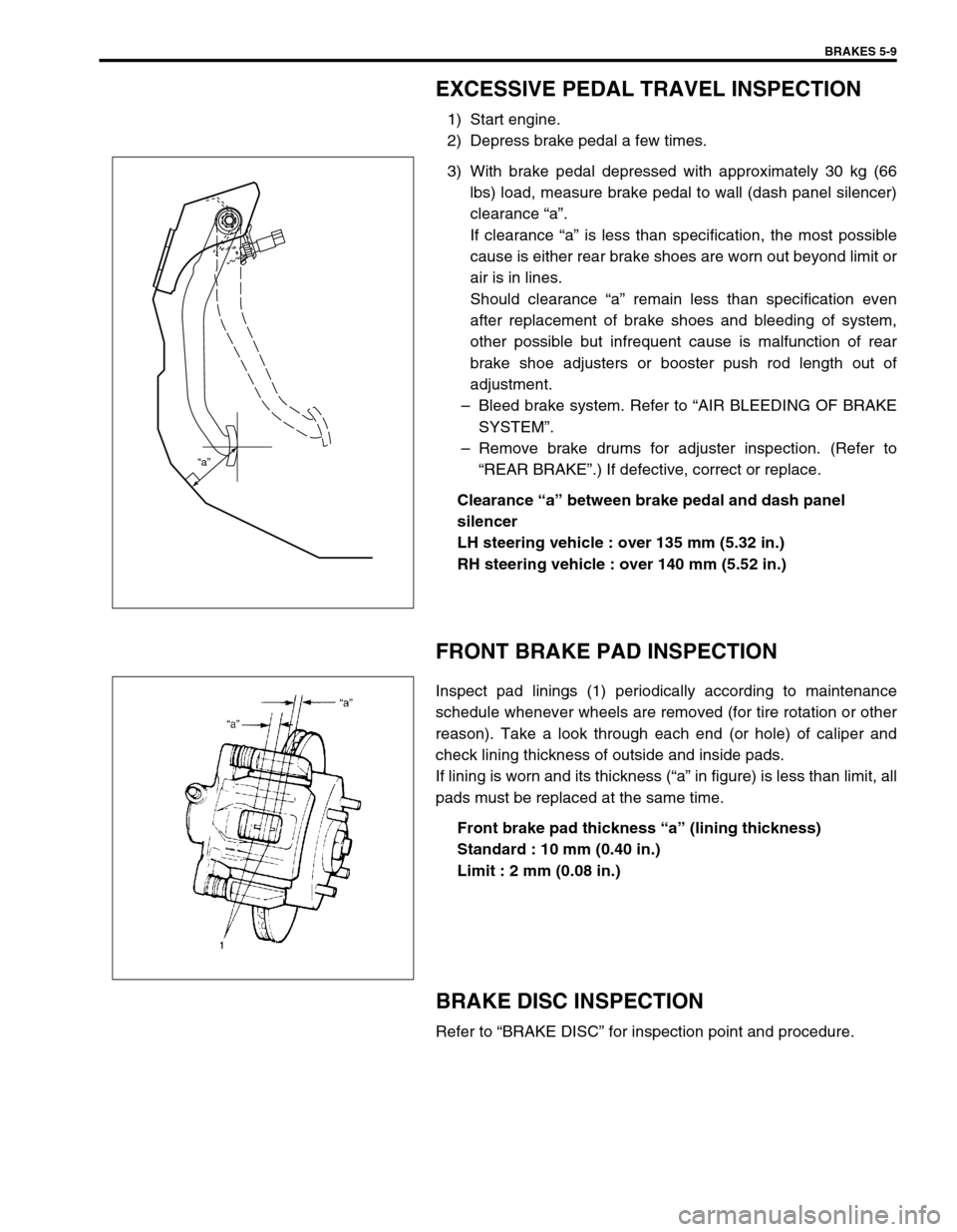
3) With brake pedal depressed with approximately 30 kg (66
lbs) load, measure brake pedal to wall (dash panel silencer)
clearance “a”.
If clearance “a” is less than specification, the most possible
cause is either rear brake shoes are worn out beyond limit or
air is in lines.
Should clearance “a” remain less than specification even
after replacement of brake shoes and bleeding of system,
other possible but infrequent cause is malfunction of rear
brake shoe adjusters or booster push rod length out of
adjustment.
–Bleed brake system. Refer to “AIR BLEEDING OF BRAKE
SYSTEM”.
–Remove brake drums for adjuster inspection. (Refer to
“REAR BRAKE”.) If defective, correct or replace.
Clearance “a” between brake pedal and dash panel
silencer
LH steering vehicle : over 135 mm (5.32 in.)
RH steering vehicle : over 140 mm (5.52 in.)
FRONT BRAKE PAD INSPECTION
Inspect pad linings (1) periodically according to maintenance
schedule whenever wheels are removed (for tire rotation or other
reason). Take a look through each end (or hole) of caliper and
check lining thickness of outside and inside pads.
If lining is worn and its thickness (“a” in figure) is less than limit, all
pads must be replaced at the same time.
Front brake pad thickness “a” (lining thickness)
Standard : 10 mm (0.40 in.)
Limit : 2 mm (0.08 in.)
BRAKE DISC INSPECTION
Refer to “BRAKE DISC” for inspection point and procedure.
“a”
Page 290 of 698

BRAKES 5-17
FRONT BRAKE
BRAKE PAD
REMOVAL
1) Loosen wheel nuts and with vehicle lifted up, remove
wheels.
2) Remove caliper pin bolts (1).
1. Brake caliper carrier 9. Bleeder plug cap
2. Boot 10. Pad spring
3. Caliper 11. Anti noise shim
4. Disc brake piston 12. Caliper pin bolt
5. Piston seal
: Apply fluid (Brake, power steering or automatic transmission fluid).13. Brake disc
6. Cylinder boot
: Apply fluid (Brake, power steering or automatic transmission fluid).14. Slide pin
: Apply lithium grease (99000-25010).
7. Brake pad Tightening torque
8. Bleeder plugDo not reuse.
9
1
7
13
2
143
1226 N·m(2.6 kg-m)
85 N·m(8.5 kg-m)
8
8.5 N·m(0.85 kg-m)
10
5 4
6
11
Page 297 of 698

5-24 BRAKES
INSPECTION
Using magnetic stand and with dial gauge positioned at
about 10 mm (0.39 in.) inward from periphery of disc, mea-
sure deflection of disc.
If limit value is exceeded, replace correct or replace.
Disc deflection
Limit : 0.10 mm (0.004 in.) max.
Special tool
(A) : 09900-20606
(B) : 09900-20701
Using micrometer, measure thickness of brake disc.
If limit value is exceeded, replace brake disc.
Brake disc thickness
Standard : 17.0 mm (0.67 in.)
Limit : 15.0 mm (0.59 in.)
INSTALLATION
1) Install disc to wheel hub.
2) Install caliper assembly to steering knuckle.
3) Torque caliper carrier bolts to specification.
Tightening torque
Caliper carrier bolts (a) : 85 N·m (8.5 kg-m, 61.5 Ib-ft)
4) Torque front wheel nuts to specification.
Tightening torque
Wheel nuts (b) : 85 N·m (8.5 kg-m, 61.5 Ib-ft)
5) Upon completion of installation, perform brake test.
Page 314 of 698

BRAKES 5-41
BRAKE HOSE/PIPE
FRONT BRAKE HOSE/PIPE
REMOVAL
1) Raise and support vehicle properly. Remove tire and wheel.
2) Clean dirt and foreign material from both flexible hose end and pipe end fittings.
3) Remove brake flexible hose or pipe.
INSTALLATION
Reverse brake flexible hose installation procedure, noting the followings.
Make sure that steering wheel is in straight-forward position and flexible hose has not twist or kink.
Check to make sure that flexible hose doesn’t contact any part of suspension, both in extreme right and
extreme left turn conditions. If it does at any point, remove and correct. Fill and maintain brake fluid level in
reservoir.
Bleed brake system. Refer to “AIR BLEEDING OF BRAKE SYSTEM”.
Perform brake test and check installed part for fluid leakage. NOTE:
This operation is not necessary when removing pipes connecting master cylinder.
Page 328 of 698
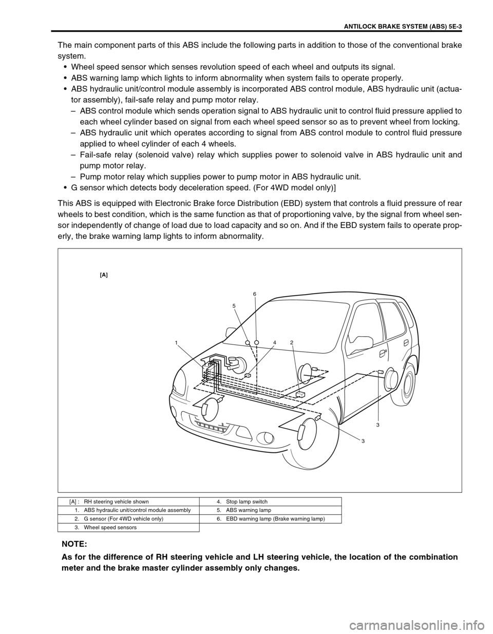
ANTILOCK BRAKE SYSTEM (ABS) 5E-3
The main component parts of this ABS include the following parts in addition to those of the conventional brake
system.
Wheel speed sensor which senses revolution speed of each wheel and outputs its signal.
ABS warning lamp which lights to inform abnormality when system fails to operate properly.
ABS hydraulic unit/control module assembly is incorporated ABS control module, ABS hydraulic unit (actua-
tor assembly), fail-safe relay and pump motor relay.
–ABS control module which sends operation signal to ABS hydraulic unit to control fluid pressure applied to
each wheel cylinder based on signal from each wheel speed sensor so as to prevent wheel from locking.
–ABS hydraulic unit which operates according to signal from ABS control module to control fluid pressure
applied to wheel cylinder of each 4 wheels.
–Fail-safe relay (solenoid valve) relay which supplies power to solenoid valve in ABS hydraulic unit and
pump motor relay.
–Pump motor relay which supplies power to pump motor in ABS hydraulic unit.
G sensor which detects body deceleration speed. (For 4WD model only)]
This ABS is equipped with Electronic Brake force Distribution (EBD) system that controls a fluid pressure of rear
wheels to best condition, which is the same function as that of proportioning valve, by the signal from wheel sen-
sor independently of change of load due to load capacity and so on. And if the EBD system fails to operate prop-
erly, the brake warning lamp lights to inform abnormality.
[A] : RH steering vehicle shown 4. Stop lamp switch
1. ABS hydraulic unit/control module assembly 5. ABS warning lamp
2. G sensor (For 4WD vehicle only) 6. EBD warning lamp (Brake warning lamp)
3. Wheel speed sensors
156
2 4
33
[A]
NOTE:
As for the difference of RH steering vehicle and LH steering vehicle, the location of the combination
meter and the brake master cylinder assembly only changes.