2000 SUZUKI SWIFT light
[x] Cancel search: lightPage 629 of 698

6E1-8 ENGINE AND EMISSION CONTROL SYSTEM
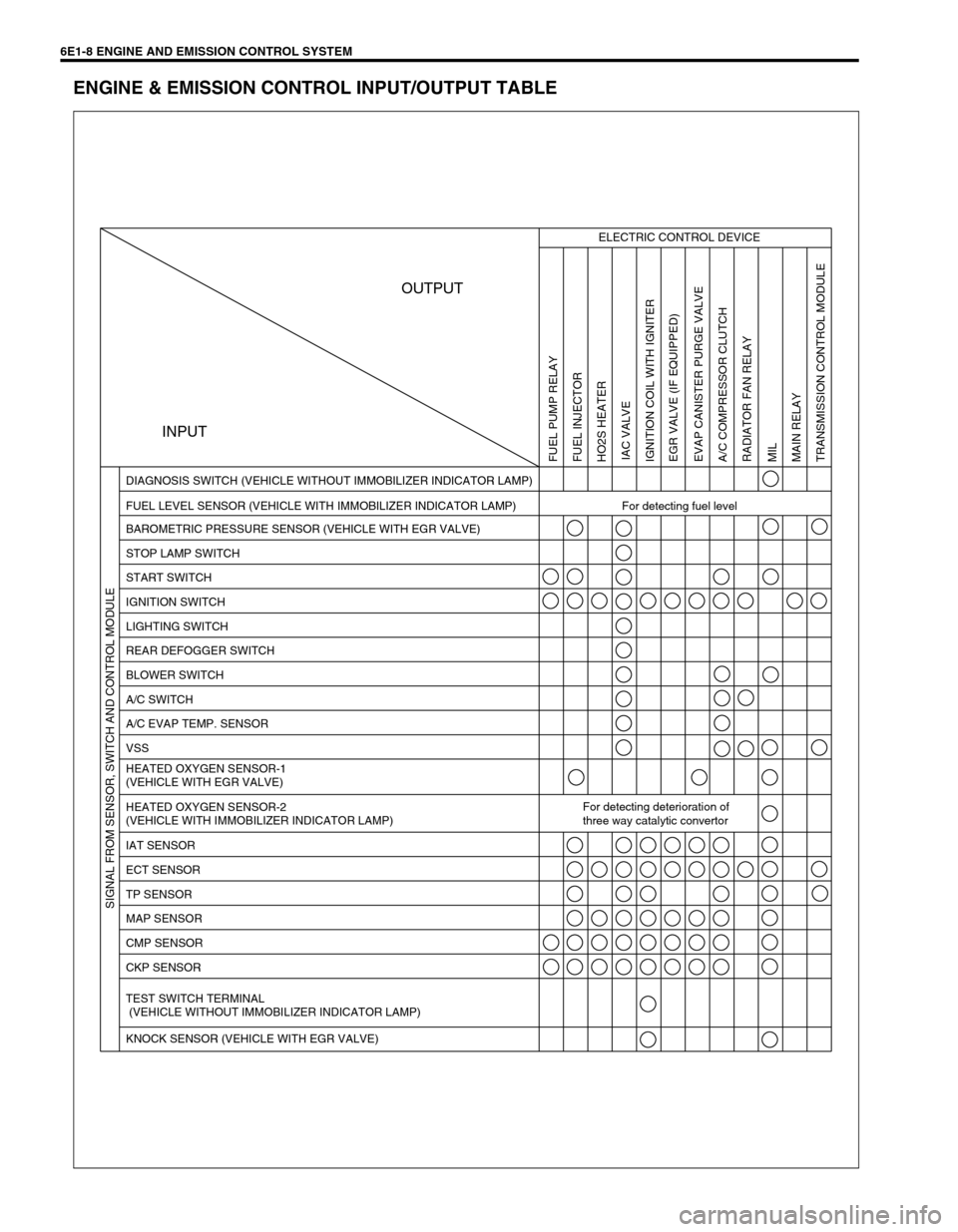
ENGINE & EMISSION CONTROL INPUT/OUTPUT TABLE
INPUTOUTPUT
ELECTRIC CONTROL DEVICE
FUEL LEVEL SENSOR (VEHICLE WITH IMMOBILIZER INDICATOR LAMP) For detecting fuel level DIAGNOSIS SWITCH (VEHICLE WITHOUT IMMOBILIZER INDICATOR LAMP)
BAROMETRIC PRESSURE SENSOR (VEHICLE WITH EGR VALVE)
STOP LAMP SWITCH
START SWITCH
IGNITION SWITCH
LIGHTING SWITCH
REAR DEFOGGER SWITCH
BLOWER SWITCH
A/C SWITCH
A/C EVAP TEMP. SENSOR
VSS
HEATED OXYGEN SENSOR-1
(VEHICLE WITH EGR VALVE)
HEATED OXYGEN SENSOR-2
(VEHICLE WITH IMMOBILIZER INDICATOR LAMP)For detecting deterioration of
three way catalytic convertor
IAT SENSOR
ECT SENSOR
TP SENSOR
MAP SENSOR
CMP SENSOR
CKP SENSOR
TEST SWITCH TERMINAL
(VEHICLE WITHOUT IMMOBILIZER INDICATOR LAMP)
KNOCK SENSOR (VEHICLE WITH EGR VALVE)
FUEL PUMP RELAY
FUEL INJECTOR
HO2S HEATER
IAC VALVE
IGNITION COIL WITH IGNITER
EGR VALVE (IF EQUIPPED)
EVAP CANISTER PURGE VALVE
A/C COMPRESSOR CLUTCH
RADIATOR FAN RELAY
MIL
MAIN RELAY
TRANSMISSION CONTROL MODULE SIGNAL FROM SENSOR, SWITCH AND CONTROL MODULE
Page 630 of 698

ENGINE AND EMISSION CONTROL SYSTEM 6E1-9
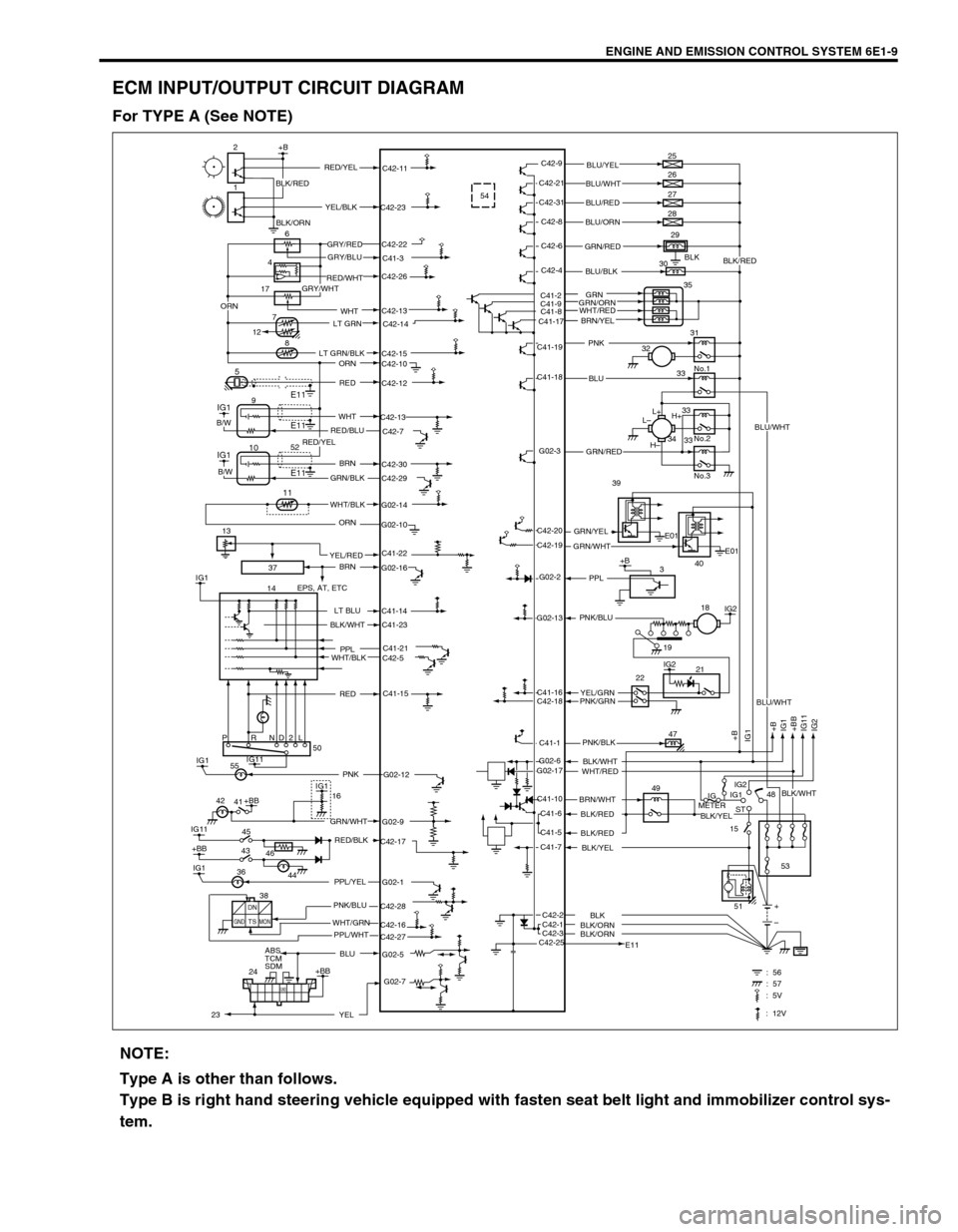
ECM INPUT/OUTPUT CIRCUIT DIAGRAM
For TYPE A (See NOTE)
37
C41-23
G02-12 IG1PNK 5554
BLK
C41-2
C41-9
C41-8
C41-17C42-13
17
2+B
1
6
8
5
IG1
IG1
14C42-9
C42-11
C42-23
C42-22
C41-3
C42-26
C42-14
C42-15
C42-10
C42-12
C42-13
C42-7
C42-30
C42-29
G02-14
G02-10
G02-16
C41-14
C41-21
C42-5
C41-15
G02-9
C42-17
G02-1
C42-28
C42-27 C42-16
G02-5C42-21
C42-31
C42-8
C42-6
C42-4
C41-19
C41-18
G02-3
G02-2
G02-13
C41-16
C42-18
C41-1
C41-10
C41-6
C41-5
C41-7
C42-1 C42-2
C42-3
C42-25G02-6
G02-173E01
E01 C42-20
C42-19L+
L–
H–H+ 25
26
27
28
29
30
35
31
No.1
No.2
No.3 32
33
33
33 34
IG2
IG2
+B
+B
IG1
+BB
IG11
IG2 IG1
21
47
49
IG
METERIG1
ST
15IG2
48
53
E11+
– 2218
PRND2L
IG11
IG11
+BB
IG145 41
ABS
TCM
SDM
24IG1
+BB50
16
E11
E1194
7
12
+BB
GND
: 56 : 57
IG1
E11 10
11
+B RED/YELBLU/YEL
BLU/WHT
BLU/RED
BLU/ORN
GRN/RED
BLU/BLK
PNK
BLU
GRN/RED
GRN/YEL39
40 GRN/WHT
PPL
YEL/GRN PNK/BLU
PNK/GRN
PNK/BLK
BLK/WHT
WHT/RED
BRN/WHT
BLK/RED
BLK/RED
BLK/YEL
BLK/ORNBLK
BLK/ORN YEL/BLK
GRY/RED
GRY/BLU
RED/WHT
GRY/WHT
LT GRN
LT GRN/BLK
ORN
RED
WHT
RED/BLU
BRN
GRN/BLK
WHT/BLK
ORN
BRN
EPS, AT, ETC
LT BLU
PPL
WHT/BLK
GRN/WHT
RED/BLK
PPL/YEL
PNK/BLU
WHT/GRN
BLU
B/W
B/W
BLK/WHT
RED
42
46 43
44 36
DN
TSGND MONPPL/WHT 38
G02-7
YEL
BLK/RED
GRN
GRN/ORN
BRN/YEL
51
2352
C41-22YEL/RED 13WHT
19
ORN
: 5V
: 12V
BLU/WHT
BLK/WHT
BLU/WHT
BLK/YEL
BLK/RED
BLK/ORN
WHT/RED
RED/YEL
NOTE:
Type A is other than follows.
Type B is right hand steering vehicle equipped with fasten seat belt light and immobilizer control sys-
tem.
Page 631 of 698

6E1-10 ENGINE AND EMISSION CONTROL SYSTEM
1. CKP sensor 20. Blank 39. Ignition coil assembly (for No.1 and No.4 spark plugs)
2. CMP sensor 21. A/C switch 40. Ignition coil assembly (for No.2 and No.3 spark plugs)
3. VSS 22. A/C pressure switch 41. Stop lamp switch
4. MAP sensor 23. Immobilizer control module 42. Stop lamp
5. Knock sensor (if equipped) 24. Data link connector 43. Lighting switch
6. TP sensor 25. Injector No.1 44. Position lamp
7. ECT sensor 26. Injector No.2 45. Rear defogger switch
8. IAT sensor 27. Injector No.3 46. Rear defogger
9. Heated oxygen sensor-1 (if equipped) 28. Injector No.4 47. A/C compressor clutch (if equipped)
10. Heated oxygen sensor-2 (if equipped) 29. IAC valve 48. Ignition switch
11. A/C evaporator temp. sensor 30. EVAP canister purge valve 49. Main relay
12. Combination meter 31. Fuel pump relay 50. Transmission range switch (A/T)
13. Fuel level sensor (vehicle with immobilizer
indicator lamp)32. Fuel pump 51. Starting motor
14. TCM 33. Radiator fan relay 52. Shield wire
15. Transmission range switch 34. Radiator fan motor 53. Main fuse
16. ABS control module 35. EGR valve (if equipped) 54. Barometric pressure sensor
17. CO adjusting resistor (if equipped) 36. Malfunction indicator lamp 55. Immobilizer indicator lamp (if equipped)
18. Heater fan motor 37. Tachometer 56. Engine ground
19. Heater fan switch 38. Monitor connector (vehicle without immo-
bilizer indicator lamp)57. Body ground
Page 633 of 698

6E1-12 ENGINE AND EMISSION CONTROL SYSTEM
1. CKP sensor 20. Blank 39. Ignition coil assembly (for No.1 and No.4 spark plugs)
2. CMP sensor 21. A/C switch 40. Ignition coil assembly (for No.2 and No.3 spark plugs)
3. VSS 22. A/C pressure switch 41. Stop lamp switch
4. MAP sensor 23. Immobilizer control module 42. Stop lamp
5. Knock sensor (if equipped) 24. Data link connector 43. Lighting switch
6. TP sensor 25. Injector No.1 44. Position lamp
7. ECT sensor 26. Injector No.2 45. Rear defogger switch
8. IAT sensor 27. Injector No.3 46. Rear defogger
9. Heated oxygen sensor-1 (if equipped) 28. Injector No.4 47. A/C compressor clutch (if equipped)
10. Blank 29. IAC valve 48. Ignition switch
11. A/C evaporator temp. sensor 30. EVAP canister purge valve 49. Main relay
12. Combination meter 31. Fuel pump relay 50. Transmission range switch (A/T)
13. Fuel level sensor (vehicle with immobilizer
indicator lamp)32. Fuel pump 51. Starting motor
14. TCM 33. Radiator fan relay 52. Shield wire
15. Transmission range switch 34. Radiator fan motor 53. Main fuse
16. ABS control module 35. EGR valve (if equipped) 54. Barometric pressure sensor
17. CO adjusting resistor (if equipped) 36. Malfunction indicator lamp 55. Immobilizer indicator lamp (if equipped)
18. Heater fan motor 37. Tachometer 56. Engine ground
19. Heater fan switch 38. Monitor connector (vehicle without immo-
bilizer indicator lamp)57. Body ground
Page 636 of 698

ENGINE AND EMISSION CONTROL SYSTEM 6E1-15
ON-VEHICLE SERVICE
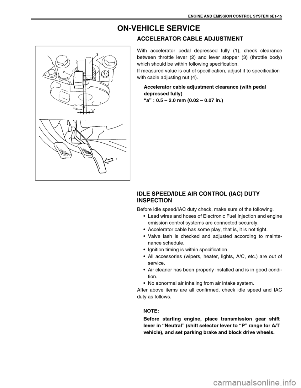
ACCELERATOR CABLE ADJUSTMENT
With accelerator pedal depressed fully (1), check clearance
between throttle lever (2) and lever stopper (3) (throttle body)
which should be within following specification.
If measured value is out of specification, adjust it to specification
with cable adjusting nut (4).
Accelerator cable adjustment clearance (with pedal
depressed fully)
“a” : 0.5 – 2.0 mm (0.02 – 0.07 in.)
IDLE SPEED/IDLE AIR CONTROL (IAC) DUTY
INSPECTION
Before idle speed/IAC duty check, make sure of the following.
Lead wires and hoses of Electronic Fuel Injection and engine
emission control systems are connected securely.
Accelerator cable has some play, that is, it is not tight.
Valve lash is checked and adjusted according to mainte-
nance schedule.
Ignition timing is within specification.
All accessories (wipers, heater, lights, A/C, etc.) are out of
service.
Air cleaner has been properly installed and is in good condi-
tion.
No abnormal air inhaling from air intake system.
After above items are all confirmed, check idle speed and IAC
duty as follows.
NOTE:
Before starting engine, place transmission gear shift
lever in “Neutral” (shift selector lever to “P” range for A/T
vehicle), and set parking brake and block drive wheels.
Page 670 of 698

6F1-8 IGNITION SYSTEM (ELECTRONIC IGNITION SYSTEM)
IGNITION TIMING
INSPECTION
1) When using SUZUKI scan tool, connect SUZUKI scan tool to
DLC with ignition switch OFF.
Special tool
(A) : 09931-76011 (SUZUKI scan tool)
(B) : Mass storage cartridge
(C) : 09931-76030 (16/14 pin DLC cable)
2) Start engine and warm it up to normal operating tempera-
ture.
3) Make sure that all of electrical loads except ignition are
switched off.
4) Check to be sure that idle speed is within specification.
(Refer to Section 6E1)
5) Fix ignition timing to initial one as follows.
Select “MISC” mode on SUZUKI scan tool and fix ignition
timing to initial one.
If scan tool is not available (vehicle without immobilizer indi-
cator lamp), connect D and E terminals of monitor connector
(1) by using service wire so that ignition timing is fixed on ini-
tial one.
6) Using timing light (1), check that ignition timing is within
specification.
Initial ignition timing (test switch terminal grounded or
fixed with SUZUKI scan tool)
: 5
± 3° BTDC at idle speed
Ignition order
: 1-3-4-2 NOTE:
Ignition timing is not adjustable. If ignition timing is
out of specification, check system related parts.
Before starting engine, place transmission gear shift
lever in “Neutral” (shift selector lever to “P” range for
A/T model), and set parking brake.
(C)
(A)
(B)
D
E1
Page 682 of 698

6H-2 CHARGING SYSTEM
GENERAL DESCRIPTION
BATTERY
The battery has three major functions in the electrical system.
It is a source of electrical energy for cranking the engine.
It acts as a voltage stabilizer for the electrical system.
It can, for a limited time, provide energy when the electrical load exceeds the output of the generator.
CARRIER AND HOLD-DOWN
The battery carrier should be in good condition so that it will support the battery securely and keep it level.
Before installing the battery, the battery carrier and hold-down clamp should be clean and free from corrosion
and make certain there are no parts in carrier.
To prevent the battery from shaking in its carrier, the hold-down bolts should be tight enough but not over-tight-
ened.
ELECTROLYTE FREEZING
The freezing point of electrolyte depends on its specific gravity. Since freezing may ruin a battery, it should be
protected against freezing by keeping it in a fully charged condition. If a battery is frozen accidentally, it should
not be charged until it is warmed.
SULFATION
If the battery is allowed to stand for a long period in discharged condition, the lead sulfate becomes converted
into a hard, crystalline substance, which will not easily turn back to the active material again during the subse-
quent recharging. “Sulfation” means the result as well as the process of that reaction. Such a battery can be
revived by very slow charging and may be restored to usable condition but its capacity is lower than before.
BUILT-IN INDICATOR (IF EQUIPPED)
The battery has a built-in temperature compensated indicator in the top of the battery. This indicator is to be
used with the following diagnostic procedure. When checking the indicator, make sure that the battery has a
clean top. A light may be needed in some poorly-lit areas.
Three types of indication available under normal operation are as
follows.
Green Dot
Battery is sufficiently charged for testing.
Dark
Battery must be charged before testing.
If there is a cranking complaint, battery should be tested as
described in Diagnosis section. Charging and electrical sys-
tems should also be checked at this time.
Clear or Light Yellow
This means that fluid level is below the bottom of hydrome-
ter. Its possible cause is excessive or prolonged charging, a
broken case, excessive tipping or normal battery deteriora-
tion. When the battery is found in such condition, it is possi-
ble that high charging voltage is caused by the faulty
charging system and therefore, charging and electrical sys-
tems need to be checked. If there is a trouble in cranking
and its cause lies in the battery, it should be replaced.
Page 684 of 698

6H-4 CHARGING SYSTEM
GENERATOR
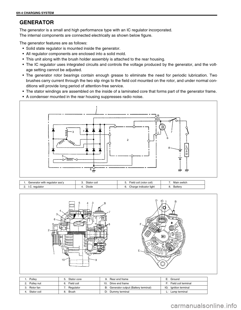
The generator is a small and high performance type with an IC regulator incorporated.
The internal components are connected electrically as shown below figure.
The generator features are as follows:
Solid state regulator is mounted inside the generator.
All regulator components are enclosed into a solid mold.
This unit along with the brush holder assembly is attached to the rear housing.
The IC regulator uses integrated circuits and controls the voltage produced by the generator, and the volt-
age setting cannot be adjusted.
The generator rotor bearings contain enough grease to eliminate the need for periodic lubrication. Two
brushes carry current through the two slip rings to the field coil mounted on the rotor, and under normal con-
ditions will provide long period of attention-free service.
The stator windings are assembled on the inside of a laminated core that forms part of the generator frame.
A condenser mounted in the rear housing suppresses radio noise.
1. Generator with regulator ass’y 3. Stator coil 5. Field coil (rotor coil) 7. Main switch
2. I.C. regulator 4. Diode 6. Charge indicator light 8. Battery
1. Pulley 5. Stator core 9. Rear end frame E: Ground
2. Pulley nut 6. Field coil 10. Drive end frame F: Field coil terminal
3. Rotor fan 7. Regulator B: Generator output (Battery terminal) IG: Ignition terminal
4. Stator coil 8. Brush D: Dummy terminal L: Lamp terminal