Page 278 of 698

BRAKES 5-5
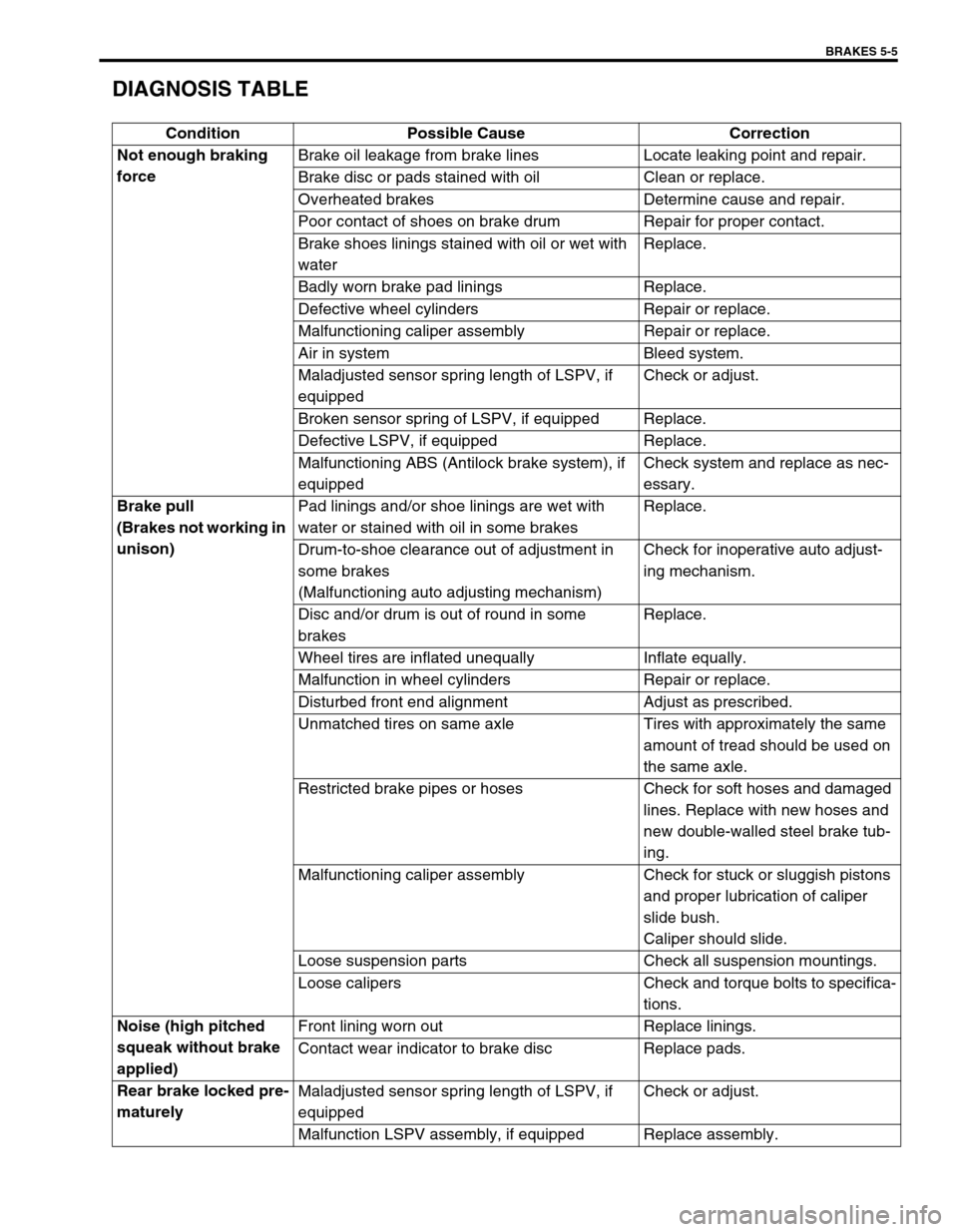
DIAGNOSIS TABLE
Condition Possible Cause Correction
Not enough braking
forceBrake oil leakage from brake lines Locate leaking point and repair.
Brake disc or pads stained with oil Clean or replace.
Overheated brakes Determine cause and repair.
Poor contact of shoes on brake drum Repair for proper contact.
Brake shoes linings stained with oil or wet with
waterReplace.
Badly worn brake pad linings Replace.
Defective wheel cylinders Repair or replace.
Malfunctioning caliper assembly Repair or replace.
Air in system Bleed system.
Maladjusted sensor spring length of LSPV, if
equippedCheck or adjust.
Broken sensor spring of LSPV, if equipped Replace.
Defective LSPV, if equipped Replace.
Malfunctioning ABS (Antilock brake system), if
equippedCheck system and replace as nec-
essary.
Brake pull
(Brakes not working in
unison)Pad linings and/or shoe linings are wet with
water or stained with oil in some brakesReplace.
Drum-to-shoe clearance out of adjustment in
some brakes
(Malfunctioning auto adjusting mechanism)Check for inoperative auto adjust-
ing mechanism.
Disc and/or drum is out of round in some
brakesReplace.
Wheel tires are inflated unequally Inflate equally.
Malfunction in wheel cylinders Repair or replace.
Disturbed front end alignment Adjust as prescribed.
Unmatched tires on same axle Tires with approximately the same
amount of tread should be used on
the same axle.
Restricted brake pipes or hoses Check for soft hoses and damaged
lines. Replace with new hoses and
new double-walled steel brake tub-
ing.
Malfunctioning caliper assembly Check for stuck or sluggish pistons
and proper lubrication of caliper
slide bush.
Caliper should slide.
Loose suspension parts Check all suspension mountings.
Loose calipers Check and torque bolts to specifica-
tions.
Noise (high pitched
squeak without brake
applied)Front lining worn out Replace linings.
Contact wear indicator to brake disc Replace pads.
Rear brake locked pre-
maturelyMaladjusted sensor spring length of LSPV, if
equippedCheck or adjust.
Malfunction LSPV assembly, if equipped Replace assembly.
Page 279 of 698

5-6 BRAKES
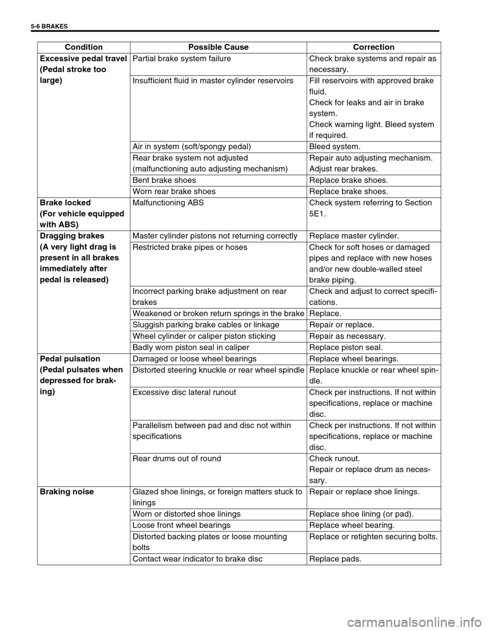
Excessive pedal travel
(Pedal stroke too
large)Partial brake system failure Check brake systems and repair as
necessary.
Insufficient fluid in master cylinder reservoirs Fill reservoirs with approved brake
fluid.
Check for leaks and air in brake
system.
Check warning light. Bleed system
if required.
Air in system (soft/spongy pedal) Bleed system.
Rear brake system not adjusted
(malfunctioning auto adjusting mechanism)Repair auto adjusting mechanism.
Adjust rear brakes.
Bent brake shoes Replace brake shoes.
Worn rear brake shoes Replace brake shoes.
Brake locked
(For vehicle equipped
with ABS)Malfunctioning ABS Check system referring to Section
5E1.
Dragging brakes
(A very light drag is
present in all brakes
immediately after
pedal is released)Master cylinder pistons not returning correctly Replace master cylinder.
Restricted brake pipes or hoses Check for soft hoses or damaged
pipes and replace with new hoses
and/or new double-walled steel
brake piping.
Incorrect parking brake adjustment on rear
brakesCheck and adjust to correct specifi-
cations.
Weakened or broken return springs in the brake Replace.
Sluggish parking brake cables or linkage Repair or replace.
Wheel cylinder or caliper piston sticking Repair as necessary.
Badly worn piston seal in caliper Replace piston seal.
Pedal pulsation
(Pedal pulsates when
depressed for brak-
ing)Damaged or loose wheel bearings Replace wheel bearings.
Distorted steering knuckle or rear wheel spindle Replace knuckle or rear wheel spin-
dle.
Excessive disc lateral runout Check per instructions. If not within
specifications, replace or machine
disc.
Parallelism between pad and disc not within
specificationsCheck per instructions. If not within
specifications, replace or machine
disc.
Rear drums out of round Check runout.
Repair or replace drum as neces-
sary.
Braking noise
Glazed shoe linings, or foreign matters stuck to
liningsRepair or replace shoe linings.
Worn or distorted shoe linings Replace shoe lining (or pad).
Loose front wheel bearings Replace wheel bearing.
Distorted backing plates or loose mounting
boltsReplace or retighten securing bolts.
Contact wear indicator to brake disc Replace pads. Condition Possible Cause Correction
Page 280 of 698

BRAKES 5-7
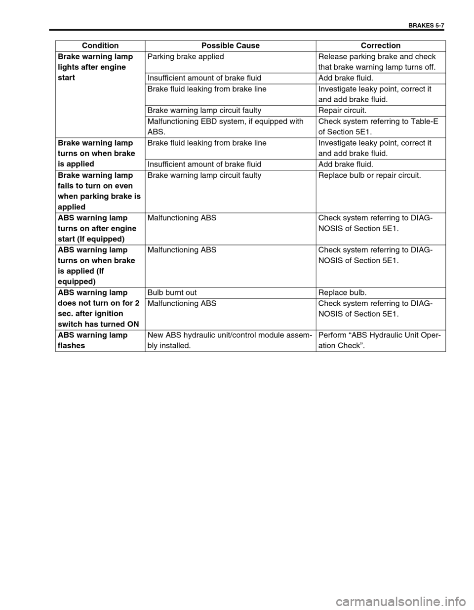
Brake warning lamp
lights after engine
startParking brake applied Release parking brake and check
that brake warning lamp turns off.
Insufficient amount of brake fluid Add brake fluid.
Brake fluid leaking from brake line Investigate leaky point, correct it
and add brake fluid.
Brake warning lamp circuit faulty Repair circuit.
Malfunctioning EBD system, if equipped with
ABS.Check system referring to Table-E
of Section 5E1.
Brake warning lamp
turns on when brake
is appliedBrake fluid leaking from brake line Investigate leaky point, correct it
and add brake fluid.
Insufficient amount of brake fluid Add brake fluid.
Brake warning lamp
fails to turn on even
when parking brake is
appliedBrake warning lamp circuit faulty Replace bulb or repair circuit.
ABS warning lamp
turns on after engine
start (If equipped)Malfunctioning ABS Check system referring to DIAG-
NOSIS of Section 5E1.
ABS warning lamp
turns on when brake
is applied (If
equipped)Malfunctioning ABS Check system referring to DIAG-
NOSIS of Section 5E1.
ABS warning lamp
does not turn on for 2
sec. after ignition
switch has turned ONBulb burnt out Replace bulb.
Malfunctioning ABS Check system referring to DIAG-
NOSIS of Section 5E1.
ABS warning lamp
flashesNew ABS hydraulic unit/control module assem-
bly installed.Perform “ABS Hydraulic Unit Oper-
ation Check”. Condition Possible Cause Correction
Page 287 of 698

5-14 BRAKES
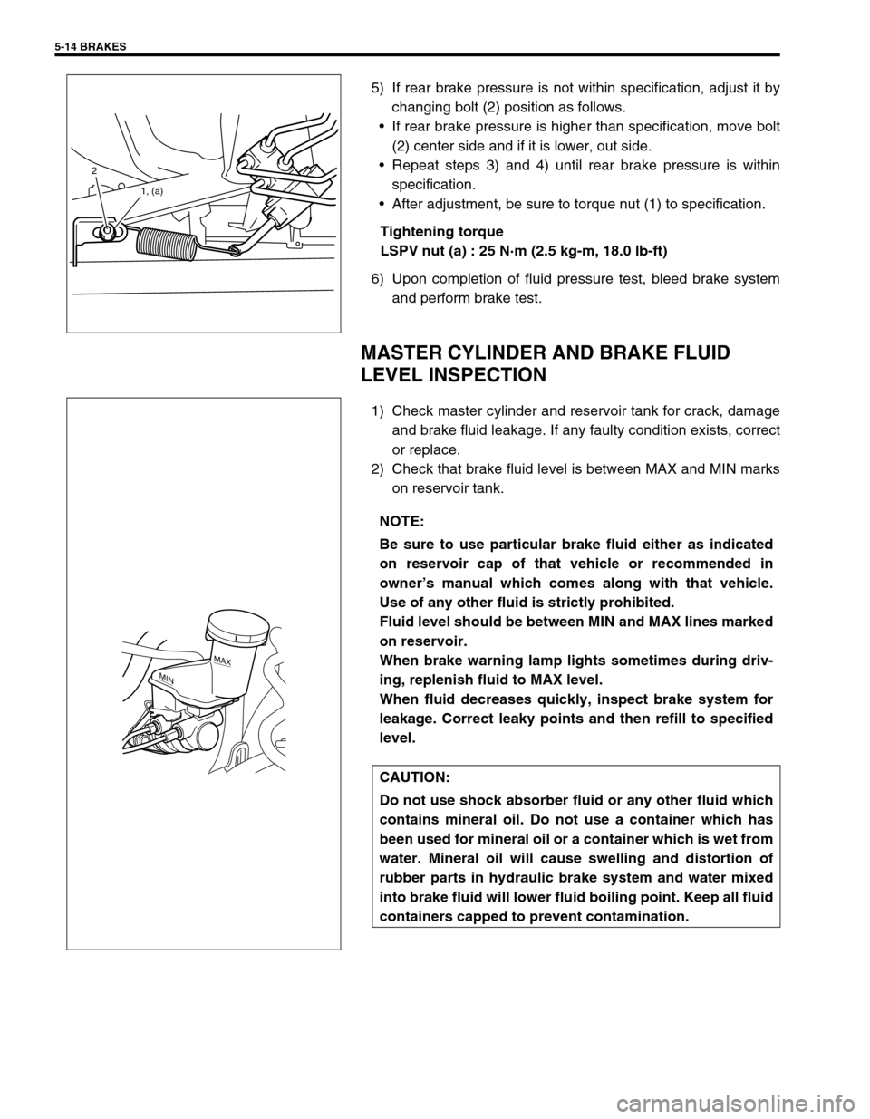
5) If rear brake pressure is not within specification, adjust it by
changing bolt (2) position as follows.
If rear brake pressure is higher than specification, move bolt
(2) center side and if it is lower, out side.
Repeat steps 3) and 4) until rear brake pressure is within
specification.
After adjustment, be sure to torque nut (1) to specification.
Tightening torque
LSPV nut (a) : 25 N·m (2.5 kg-m, 18.0 lb-ft)
6) Upon completion of fluid pressure test, bleed brake system
and perform brake test.
MASTER CYLINDER AND BRAKE FLUID
LEVEL INSPECTION
1) Check master cylinder and reservoir tank for crack, damage
and brake fluid leakage. If any faulty condition exists, correct
or replace.
2) Check that brake fluid level is between MAX and MIN marks
on reservoir tank.
2
1, (a)
NOTE:
Be sure to use particular brake fluid either as indicated
on reservoir cap of that vehicle or recommended in
owner’s manual which comes along with that vehicle.
Use of any other fluid is strictly prohibited.
Fluid level should be between MIN and MAX lines marked
on reservoir.
When brake warning lamp lights sometimes during driv-
ing, replenish fluid to MAX level.
When fluid decreases quickly, inspect brake system for
leakage. Correct leaky points and then refill to specified
level.
CAUTION:
Do not use shock absorber fluid or any other fluid which
contains mineral oil. Do not use a container which has
been used for mineral oil or a container which is wet from
water. Mineral oil will cause swelling and distortion of
rubber parts in hydraulic brake system and water mixed
into brake fluid will lower fluid boiling point. Keep all fluid
containers capped to prevent contamination.
MAX
MIN
Page 310 of 698
BRAKES 5-37
7) Install cup (1) and washer (2) such a direction as shown.
8) Remove cap cup (1) from cap with caring not to cause any
damage to inside of cap (2).
9) Install cap cup and O-rings (3) to cap such a direction as
shown.
10) Install cap and tighten it to specified torque, then confirm the
length “A”.
Tightening torque
Cap (a) : 14 N·m (1.4 kg-m, 10.5 lb-ft)
Cap installation position
“A” : Less than 26 mm (1.02 in.)
INSPECTION AFTER ASSEMBLY
1) Install radiator cap test with special tool to master cylinder
port (1).
Special tool
(A) : 09952-46010
(B) : 09952-26020
2) Apply air and confirm that pressure is not applied.NOTE:
Primary cup is the same as secondary cup.
Primary cup is the largest compared with that of cap
and sleeve.
NOTE:
For without ABS vehicle, install special tool (B) to oppo-
site side port (2).
1(B)
2 (A)
Page 315 of 698
5-42 BRAKES
For vehicle with ABS
T : Top side [A] : For left-hand steering vehicle 4. From ABS hydraulic unit to right front brake
F : Front side [B] : For right-hand steering vehicle 5. ABS hydraulic unit
R : Right side 1. From master cylinder primary to ABS hydraulic unit 6. Master cylinder
A : View A 2. From master cylinder secondary to ABS hydraulic unit 7. Front brake hose
a-f: Clamp 3. From ABS hydraulic unit to left front brake Tightening torque
Page 316 of 698
BRAKES 5-43
For vehicle without ABS
T : Top side 1. From master cylinder primary to left front brake [A] : For left-hand steering vehicle
F : Front side 2. From master cylinder secondary to right front brake [B] : For right-hand steering vehicle
R : Right side 3. Master cylinder a-g: Clamp
A : View A 4. Front brake hose Tightening torque
Page 318 of 698
BRAKES 5-45
T : Top side 1. 4 way joint [A] : with ABS
F : Front side 2. LSPV assembly [B] : without ABS
R : Right side 3. P valve [C] : with LSPV
L : Left side 4. Rear brake hose Tightening torque
B : View B a-g: Clamp