Page 274 of 698

BRAKES 5-1
6F1
6F2
6G
6H
6K
7A
7A1
7B1
7C1
7D
7E
7F
8A
8B
8C
5
9
10
10A
10B
SECTION 5
BRAKES
CONTENTS
GENERAL DESCRIPTION ................................ 5-2
DIAGNOSIS ....................................................... 5-4
ROAD TESTING BRAKES ............................. 5-4
BRAKE FLUID LEAKS ................................... 5-4
SUBSTANDARD OR CONTAMINATED
BRAKE FLUID ................................................ 5-4
DIAGNOSIS TABLE ....................................... 5-5
BRAKE PEDAL FREE HEIGHT
ADJUSTMENT ............................................... 5-8
BRAKE PEDAL PLAY INSPECTION ............. 5-8
STOP LIGHT SWITCH ADJUSTMENT.......... 5-8
EXCESSIVE PEDAL TRAVEL
INSPECTION ................................................. 5-9
FRONT BRAKE PAD INSPECTION .............. 5-9
BRAKE DISC INSPECTION........................... 5-9
PARKING BRAKE INSPECTION AND
ADJUSTMENT ............................................. 5-10
BOOSTER OPERATION INSPECTION....... 5-11
FLUID PRESSURE TEST (IF EQUIPPED
WITH LSPV) ................................................ 5-12
MASTER CYLINDER AND BRAKE FLUID
LEVEL INSPECTION ................................... 5-14
BRAKE HOSE AND PIPE INSPECTION ..... 5-15
HOSE ....................................................... 5-15
PIPE ......................................................... 5-15
ON-VEHICLE SERVICE .................................. 5-15AIR BLEEDING OF BRAKE SYSTEM ......... 5-15
FRONT BRAKE ........................................... 5-17
BRAKE PAD............................................. 5-17
CALIPER ASSEMBLY ............................. 5-19
BRAKE DISC ........................................... 5-23
REAR BRAKE .............................................. 5-25
BRAKE DRUM ......................................... 5-26
BRAKE SHOE .......................................... 5-29
WHEEL CYLINDER ................................. 5-30
BRAKE BACK PLATE (FOR 2WD
VEHICLE)................................................. 5-31
BRAKE BACK PLATE (FOR 4WD
VEHICLE)................................................. 5-33
MASTER CYLINDER ................................... 5-33
MASTER CYLINDER RESERVOIR ......... 5-33
MASTER CYLINDER ASSEMBLY........... 5-34
BRAKE BOOSTER ...................................... 5-38
BRAKE HOSE/PIPE .................................... 5-41
FRONT BRAKE HOSE/PIPE ................... 5-41
REAR BRAKE HOSE/PIPE...................... 5-44
PARKING BRAKE CABLE ........................... 5-46
LSPV (LOAD SENSING PROPORTIONING
VALVE) ASSEMBLY (IF EQUIPPED).......... 5-48
REQUIRED SERVICE MATERIAL.................. 5-50
SPECIAL TOOL .............................................. 5-50
NOTE:
All front fasteners are important attaching parts in that they could affect the performance of vital parts
and systems, and/or could result in major repair expense. They must be replaced with one of same
part number or with an equivalent part if replacement becomes necessary. Do not use a replacement
part of lesser quality or substitute design. Torque values must be used as specified during reassem-
bly to assure proper retention of all parts. There is to be no welding as it may result in extensive dam-
age and weakening of the metal.
Page 275 of 698
5-2 BRAKES
GENERAL DESCRIPTION
When the foot brake pedal is depressed, hydraulic pressure is developed in the master cylinder to actuate pis-
tons (two in front and four in rear).
The master cylinder is a tandem master cylinder. Brake pipes are connected to the master cylinder and they
make two independent circuits. One connects front right & rear left brakes and the other connects front left &
rear right brakes.
The load sensing proportioning valve (LSPV) or the proportioning valve (P valve) is included in these circuits
between the master cylinder and the rear brake for the vehicle without ABS.
In this brake system, the disc brake type is used for the front wheel brake and a drum brake type (leading/trailing
shoes) for the rear brake.
The parking brake system is mechanical. It applies brake force to only rear wheels by means of the cable and
mechanical linkage system. The same brake shoes are used for both parking and foot brakes.
Page 276 of 698
BRAKES 5-3
NOTE:
The figures shows left-hand steering vehicle.
[A] : For vehicle without ABS 3. Secondary side 7. LSPV (Load Sensing Proportioning valve)
[B] : For vehicle with ABS 4. Primary side 8. P (Proportioning) valve
1. Brake booster 5. 4-way joint A: Forward
2. Master cylinder 6. ABS hydraulic unit/control module assembly
Page 318 of 698
BRAKES 5-45
T : Top side 1. 4 way joint [A] : with ABS
F : Front side 2. LSPV assembly [B] : without ABS
R : Right side 3. P valve [C] : with LSPV
L : Left side 4. Rear brake hose Tightening torque
B : View B a-g: Clamp
Page 321 of 698
5-48 BRAKES
LSPV (LOAD SENSING PROPORTIONING VALVE) ASSEMBLY (IF EQUIPPED)
REMOVAL
1) Clean around reservoir cap and take out fluid with syringe or
such.
2) Hoist vehicle.
3) Disconnect brake pipes from LSPV assembly.
Special tool
09950-78230 (10 x 11 mm)
4) Remove nut (2) and detach spring end from rear axle (3).
5) Remove LSPV assembly (1) with spring (4) from vehicle
body.
1. LSPV assembly 3. Adjust nut Tightening torque
2. Spring 4. Brake pipe
CAUTION:
Never disassemble LSPV assembly. Disassembly will
spoil its original performance. Replace with new one if
detective.
3
21
25 N·m(2.5 kg-m)
4 16 N·m(1.6 kg-m)
25 N·m(2.5 kg-m)
3
24
1
Page 328 of 698

ANTILOCK BRAKE SYSTEM (ABS) 5E-3
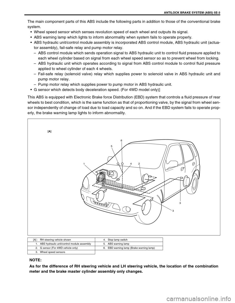
The main component parts of this ABS include the following parts in addition to those of the conventional brake
system.
Wheel speed sensor which senses revolution speed of each wheel and outputs its signal.
ABS warning lamp which lights to inform abnormality when system fails to operate properly.
ABS hydraulic unit/control module assembly is incorporated ABS control module, ABS hydraulic unit (actua-
tor assembly), fail-safe relay and pump motor relay.
–ABS control module which sends operation signal to ABS hydraulic unit to control fluid pressure applied to
each wheel cylinder based on signal from each wheel speed sensor so as to prevent wheel from locking.
–ABS hydraulic unit which operates according to signal from ABS control module to control fluid pressure
applied to wheel cylinder of each 4 wheels.
–Fail-safe relay (solenoid valve) relay which supplies power to solenoid valve in ABS hydraulic unit and
pump motor relay.
–Pump motor relay which supplies power to pump motor in ABS hydraulic unit.
G sensor which detects body deceleration speed. (For 4WD model only)]
This ABS is equipped with Electronic Brake force Distribution (EBD) system that controls a fluid pressure of rear
wheels to best condition, which is the same function as that of proportioning valve, by the signal from wheel sen-
sor independently of change of load due to load capacity and so on. And if the EBD system fails to operate prop-
erly, the brake warning lamp lights to inform abnormality.
[A] : RH steering vehicle shown 4. Stop lamp switch
1. ABS hydraulic unit/control module assembly 5. ABS warning lamp
2. G sensor (For 4WD vehicle only) 6. EBD warning lamp (Brake warning lamp)
3. Wheel speed sensors
156
2 4
33
[A]
NOTE:
As for the difference of RH steering vehicle and LH steering vehicle, the location of the combination
meter and the brake master cylinder assembly only changes.
Page 332 of 698

ANTILOCK BRAKE SYSTEM (ABS) 5E-7
1. Battery 9. ABS hydraulic unit/control module assembly 17. Left-rear wheel speed sensor
2. Main fuses 10. Terminal arrangement of connector E19 for ABS
hydraulic unit/control module assembly18. Right-front wheel speed sensor
3. Ignition switch 11. ABS fail-safe relay (Solenoid valve relay) 19. Left-front wheel speed sensor
4. Circuit fuses 12. ABS pump motor relay 20. Data link connector
5. Combination meter 13. Pump motor 21. To ECM, SDM and EPS controller (if equipped)
6. ABS warning lamp 14. Solenoid valves 22. Stop lamp
7. Brake warning lamp (“EBD” warning lamp) 15. Diagnosis monitor coupler 23. Stop lamp switch
8. Warning lamp driver module (for ABS) 16. Right-rear wheel speed sensor 24. G sensor (For 4WD vehicle only)
Wire color
BLK : Black LT GRN/BLK : Light Green/Black RED/BLU : Red/Blue
BLK/ORN : Black/Orange LT GRN/RED : Light Green/Red WHT : White
BLK/YEL : Black/Yellow ORN : Orange WHT/BLK : White/Black
BLU : Blue PNK : Pink WHT/BLU : White/Blue
BRN : Brown PNK/BLU Pink/Blue WHT/RED : White/Red
GRN : Green RED : Red YEL : Yellow
GRN/ORN : Green/Orange RED/BLK : Red/Black
TERMINAL CIRCUIT
E191–
2 Stop lamp switch
3 Right-front wheel speed sensor (+)
4 Right-front wheel speed sensor (–)
5–
6 Right-rear wheel speed sensor (–)
7 Right-rear wheel speed sensor (+)
8–
9–
10 Brake warning lamp (EBD warning lamp)
11 G sensor (For 4WD vehicle only)
12 Diagnosis switch terminal
13 Ground (For G sensor) (For 4WD vehicle only)
14 ABS warning lamp
15 Left-front wheel speed sensor (+)
16 Left-front wheel speed sensor (–)
17–
18 Ignition switch
19 Left-rear wheel speed sensor (+)
20 Left-rear wheel speed sensor (–)
21 Data link connector
22 Ground (for ABS pump motor)
23 ABS pump motor relay
24 Ground (for ABS control module)
25 ABS fail-safe relay
Page 346 of 698
ANTILOCK BRAKE SYSTEM (ABS) 5E-21
C1022 22 RF
Wheel speed sensor circuit
or sensor ring C1026 26 LF
C1032 32 RR
C1036 36 LR
C1041 41
RFInlet solenoid valve circuit
C1042 42 Outlet solenoid valve circuit
C1045 45
LFInlet solenoid valve circuit
C1046 46 Outlet solenoid valve circuit
C1051 51
RRInlet solenoid valve circuit
C1052 52 Outlet solenoid valve circuit
C1055 55
LRInlet solenoid valve circuit
C1056 56 Outlet solenoid valve circuit
C1057 57 Power source
C1061 61 ABS pump motor and/or motor relay circuit
C1063 63 Fail safe-relay
C1071 71 ABS control moduleDTC
(displayed
on SUZUKI
scan tool)DTC
(indicated by
ABS warning
lamp)ABS warning lamp flashing
patternDIAGNOSTIC ITEMS