2000 SUZUKI SWIFT engine oil
[x] Cancel search: engine oilPage 374 of 698

ENGINE GENERAL INFORMATION AND DIAGNOSIS 6-5
PRECAUTION ON FUEL SYSTEM SERVICE
Work must be done with no smoking, in a well-ventilated
area and away from any open flames.
As fuel feed line (between fuel pump and fuel delivery pipe)
is still under high fuel pressure even after engine was
stopped, loosening or disconnecting fuel feed line directly
may cause dangerous spout of fuel to occur where loosened
or disconnected.
Before loosening or disconnecting fuel feed line, make sure
to release fuel pressure according to “FUEL PRESSURE
RELIEF PROCEDURE”. A small amount of fuel may be
released after the fuel line is disconnected. In order to
reduce the chance of personal injury, cover the fitting to be
disconnected with a shop cloth. Put that cloth in an approved
container when disconnection is completed.
Never run engine with fuel pump relay disconnected when
engine and exhaust system are hot.
Fuel or fuel vapor hose connection varies with each type of
pipe. When reconnecting fuel or fuel vapor hose, be sure to
connect and clamp each hose correctly referring to figure
Hose Connection.
After connecting, make sure that it has no twist or kink.
When installing injector or fuel delivery pipe, lubricate its O-
ring with spindle oil or gasoline.
When connecting fuel pipe flare nut, first tighten flare nut by
hand and then tighten it to specified torque.
[A] : With short pipe, fit hose as far as it reaches pipe joint as shown.
[B] : With following type pipe, fit hose as far as its peripheral projection as shown.
[C] : With bent pipe, fit hose as its bent part as shown or till pipe is about 20 to 30 mm
(0.79–1.18 in.) into the hose.
[D] : With straight pipe, fit hose till pipe is, about 20 to 30 mm (0.79–1.18 in.) into the
hose.
1. Hose
2. Pipe
3. Clamp
4. Clamp securely at a position 3 to 7 mm (0.1 2–0.27 in.) from hose end.
5. 20 to 30 mm (0.79–1.18 in.)
Page 391 of 698

6-22 ENGINE GENERAL INFORMATION AND DIAGNOSIS
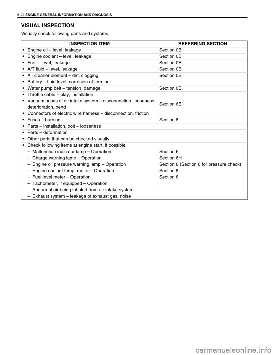
VISUAL INSPECTION
Visually check following parts and systems.
INSPECTION ITEM REFERRING SECTION
Engine oil – level, leakage Section 0B
Engine coolant – level, leakage Section 0B
Fuel – level, leakage Section 0B
A/T fluid – level, leakage Section 0B
Air cleaner element – dirt, clogging Section 0B
Battery – fluid level, corrosion of terminal
Water pump belt – tension, damage Section 0B
Throttle cable – play, installation
Section 6E1 Vacuum hoses of air intake system – disconnection, looseness,
deterioration, bend
Connectors of electric wire harness – disconnection, friction
Fuses – burning Section 8
Parts – installation, bolt – looseness
Parts – deformation
Other parts that can be checked visually
Check following items at engine start, if possible
–Malfunction indicator lamp – Operation Section 6
–Charge warning lamp – Operation Section 6H
–Engine oil pressure warning lamp – Operation Section 8 (Section 6 for pressure check)
–Engine coolant temp. meter – Operation Section 8
–Fuel level meter – Operation Section 8
–Tachometer, if equipped – Operation
–Abnormal air being inhaled from air intake system
–Exhaust system – leakage of exhaust gas, noise
Page 395 of 698

6-26 ENGINE GENERAL INFORMATION AND DIAGNOSIS
ENGINE DIAGNOSIS TABLE
Perform troubleshooting referring to following table when ECM has detected no DTC and no abnormality has
been found in visual inspection and engine basic inspection previously.
Condition Possible Cause Correction
Hard Starting
(Engine cranks OK) Faulty spark plug Spark plugs in Section 6F1.
Leaky high-tension cord High-tension cords in Section 6F1.
Loose connection or disconnection of high-
tension cords or lead wiresHigh-tension cords in Section 6F1.
Faulty ignition coil Ignition coil in Section 6F1.
Dirty or clogged fuel hose or pipe Diagnostic Flow Table B-3.
Malfunctioning fuel pump Diagnostic Flow Table B-3.
Air inhaling from intake manifold gasket or
throttle body gasket
Faulty idle air control system Diagnostic Flow Table B-4.
Faulty ECT sensor or MAP sensor ECT sensor or MAP sensor in Section
6E1.
Faulty ECM
Hard Starting
(Engine cranks OK) Poor spark plug tightening or faulty gasket Spark plugs in Section 6F1.
Compression leak from valve seat Valves inspection in Section 6A1.
Sticky valve stem Valves inspection in Section 6A1.
Weak or damaged valve springs Valve springs inspection in Section
6A1.
Compression leak at cylinder head gasket Cylinder head inspection in Section
6A1.
Sticking or damaged piston ring Cylinders, pistons and piston rings
inspection in Section 6A1.
Worn piston, ring or cylinder Cylinders, pistons and piston rings
inspection in Section 6A1.
Malfunctioning PCV valve PCV system in Section 6E1.
Low compression Compression check in Section 6A1.
Low oil pressure
Improper oil viscosity Engine oil and oil filter change in Sec-
tion 0B.
Malfunctioning oil pressure switch Oil pressure switch inspection in Sec-
tion 8.
Clogged oil strainer Oil pan and oil pump strainer cleaning
in Section 6A1.
Functional deterioration of oil pump Oil pump in Section 6A1.
Worn oil pump relief valve Oil pump in Section 6A1.
Excessive clearance in various sliding parts
Page 396 of 698

ENGINE GENERAL INFORMATION AND DIAGNOSIS 6-27
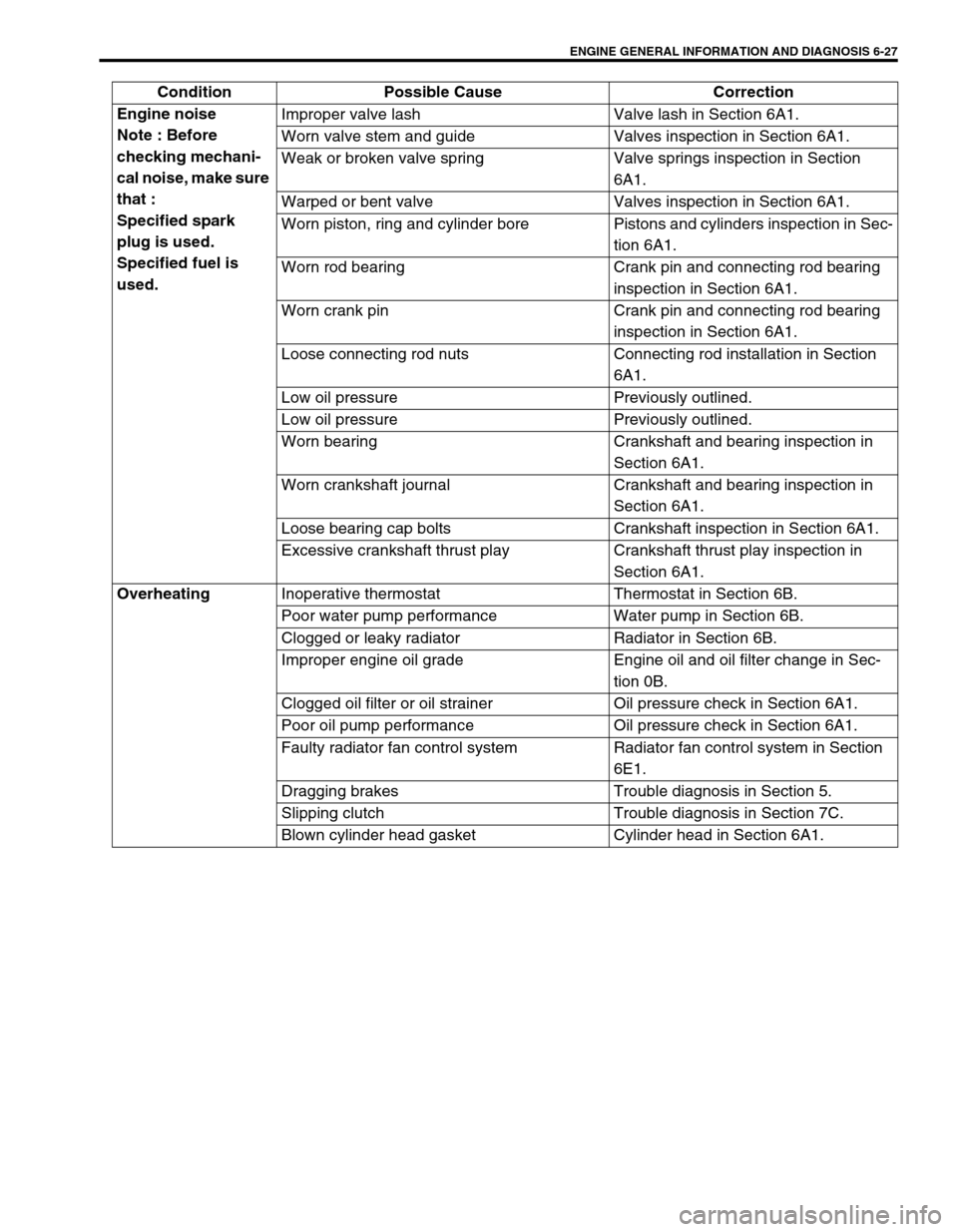
Engine noise
Note : Before
checking mechani-
cal noise, make sure
that :
Specified spark
plug is used.
Specified fuel is
used.Improper valve lash Valve lash in Section 6A1.
Worn valve stem and guide Valves inspection in Section 6A1.
Weak or broken valve spring Valve springs inspection in Section
6A1.
Warped or bent valve Valves inspection in Section 6A1.
Worn piston, ring and cylinder bore Pistons and cylinders inspection in Sec-
tion 6A1.
Worn rod bearing Crank pin and connecting rod bearing
inspection in Section 6A1.
Worn crank pin Crank pin and connecting rod bearing
inspection in Section 6A1.
Loose connecting rod nuts Connecting rod installation in Section
6A1.
Low oil pressure Previously outlined.
Low oil pressure Previously outlined.
Worn bearing Crankshaft and bearing inspection in
Section 6A1.
Worn crankshaft journal Crankshaft and bearing inspection in
Section 6A1.
Loose bearing cap bolts Crankshaft inspection in Section 6A1.
Excessive crankshaft thrust play Crankshaft thrust play inspection in
Section 6A1.
Overheating
Inoperative thermostat Thermostat in Section 6B.
Poor water pump performance Water pump in Section 6B.
Clogged or leaky radiator Radiator in Section 6B.
Improper engine oil grade Engine oil and oil filter change in Sec-
tion 0B.
Clogged oil filter or oil strainer Oil pressure check in Section 6A1.
Poor oil pump performance Oil pressure check in Section 6A1.
Faulty radiator fan control system Radiator fan control system in Section
6E1.
Dragging brakes Trouble diagnosis in Section 5.
Slipping clutch Trouble diagnosis in Section 7C.
Blown cylinder head gasket Cylinder head in Section 6A1. Condition Possible Cause Correction
Page 397 of 698

6-28 ENGINE GENERAL INFORMATION AND DIAGNOSIS
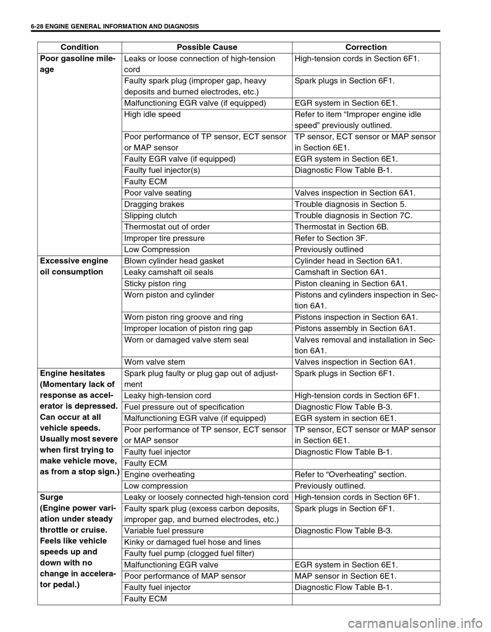
Poor gasoline mile-
age Leaks or loose connection of high-tension
cordHigh-tension cords in Section 6F1.
Faulty spark plug (improper gap, heavy
deposits and burned electrodes, etc.)Spark plugs in Section 6F1.
Malfunctioning EGR valve (if equipped) EGR system in Section 6E1.
High idle speed Refer to item “Improper engine idle
speed” previously outlined.
Poor performance of TP sensor, ECT sensor
or MAP sensorTP sensor, ECT sensor or MAP sensor
in Section 6E1.
Faulty EGR valve (if equipped) EGR system in Section 6E1.
Faulty fuel injector(s) Diagnostic Flow Table B-1.
Faulty ECM
Poor valve seating Valves inspection in Section 6A1.
Dragging brakes Trouble diagnosis in Section 5.
Slipping clutch Trouble diagnosis in Section 7C.
Thermostat out of order Thermostat in Section 6B.
Improper tire pressure Refer to Section 3F.
Low Compression Previously outlined
Excessive engine
oil consumption Blown cylinder head gasket Cylinder head in Section 6A1.
Leaky camshaft oil seals Camshaft in Section 6A1.
Sticky piston ring Piston cleaning in Section 6A1.
Worn piston and cylinder Pistons and cylinders inspection in Sec-
tion 6A1.
Worn piston ring groove and ring Pistons inspection in Section 6A1.
Improper location of piston ring gap Pistons assembly in Section 6A1.
Worn or damaged valve stem seal Valves removal and installation in Sec-
tion 6A1.
Worn valve stem Valves inspection in Section 6A1.
Engine hesitates
(Momentary lack of
response as accel-
erator is depressed.
Can occur at all
vehicle speeds.
Usually most severe
when first trying to
make vehicle move,
as from a stop sign.)Spark plug faulty or plug gap out of adjust-
mentSpark plugs in Section 6F1.
Leaky high-tension cord High-tension cords in Section 6F1.
Fuel pressure out of specification Diagnostic Flow Table B-3.
Malfunctioning EGR valve (if equipped) EGR system in section 6E1.
Poor performance of TP sensor, ECT sensor
or MAP sensorTP sensor, ECT sensor or MAP sensor
in Section 6E1.
Faulty fuel injector Diagnostic Flow Table B-1.
Faulty ECM
Engine overheating Refer to “Overheating” section.
Low compression Previously outlined.
Surge
(Engine power vari-
ation under steady
throttle or cruise.
Feels like vehicle
speeds up and
down with no
change in accelera-
tor pedal.)Leaky or loosely connected high-tension cord High-tension cords in Section 6F1.
Faulty spark plug (excess carbon deposits,
improper gap, and burned electrodes, etc.)Spark plugs in Section 6F1.
Variable fuel pressure Diagnostic Flow Table B-3.
Kinky or damaged fuel hose and lines
Faulty fuel pump (clogged fuel filter)
Malfunctioning EGR valve EGR system in Section 6E1.
Poor performance of MAP sensor MAP sensor in Section 6E1.
Faulty fuel injector Diagnostic Flow Table B-1.
Faulty ECM Condition Possible Cause Correction
Page 398 of 698

ENGINE GENERAL INFORMATION AND DIAGNOSIS 6-29
Excessive detona-
tion
(Engine makes con-
tinuously sharp
metallic knocks that
change with throttle
opening. Sounds
like pop corn pop-
ping.)Faulty spark plug Spark plugs in Section 6F1.
Loose connection of high-tension cord High-tension cords in Section 6F1.
Engine overheating Refer to “Overheating” section.
Clogged fuel filter (faulty fuel pump) or fuel
linesDiagnostic Flow Table B-1 or B-2.
Air inhaling from intake manifold or throttle
body gasket
Malfunctioning EGR valve (if equipped) EGR system in Section 6E1.
Poor performance of knock sensor, ECT sen-
sor or MAP sensorKnock sensor in Section 6, ECT sensor
or MAP sensor in Section 6E1.
Faulty fuel injector(s) Diagnostic Flow Table B-1.
Faulty ECM
Excessive combustion chamber deposits Piston and cylinder head cleaning in
Section 6A1.
Engine has no
powerFaulty spark plug Spark plugs in Section 6F1.
Faulty ignition coil with ignitor Ignition coil in Section 6F1.
Leaks, loose connection or disconnection of
high-tension cordHigh-tension cords in Section 6F1.
Faulty knock sensor Knock sensor malfunction in this sec-
tion.
Clogged fuel hose or pipe Diagnostic Flow Table B-3.
Malfunctioning fuel pump Diagnostic Flow Table B-2.
Air inhaling from intake manifold gasket or
throttle body gasket
Engine overheating Refer to “Overheating” section.
Engine has no
powerMalfunctioning EGR valve (if equipped) EGR system inspection in Section 6E1.
Maladjusted accelerator cable play Accelerator cable play in Section 6E1.
Poor performance of TP sensor, ECT sensor
or MAP sensorTP sensor, ECT sensor or MAP sensor
in Section 6E1.
Faulty fuel injector(s) Diagnostic Flow Table B-1.
Faulty ECM
Dragging brakes Trouble diagnosis in Section 5.
Slipping clutch Trouble diagnosis in Section 7C.
Low compression Previously outlined. Condition Possible Cause Correction
Page 399 of 698

6-30 ENGINE GENERAL INFORMATION AND DIAGNOSIS
Improper engine
idling or engine fails
to idleFaulty spark plug Spark plugs in Section 6F1.
Leaky or disconnected high-tension cord High-tension cords in Section 6F1.
Faulty ignition coil with ignitor Ignition coil in Section 6F1.
Fuel pressure out of specification Diagnostic Flow Table B-3.
Leaky manifold, throttle body, or cylinder
head gasket
Malfunctioning EGR valve (if equipped) EGR system in Section 6E1.
Faulty idle air control system Diagnostic Flow Table B-4.
Faulty evaporative emission control system EVAP control system in Section 6E1.
Faulty EGR system (if equipped) EGR system in Section 6E1.
Faulty fuel injector(s) Diagnostic Flow Table B-1.
Poor performance of ECT sensor, TP sensor
or MAP sensorECT sensor, TP sensor or MAP sensor
in Section 6E1.
Faulty ECM
Loose connection or disconnection of vacuum
hoses
Malfunctioning PCV valve PCV system in Section 6E1.
Engine overheating Refer to “Overheating” section.
Low compression Previously outlined.
Excessive hydrocar-
bon (HC) emission
or carbon monox-
ide (CO)Faulty spark plug Spark plugs in Section 6F1.
Leaky or disconnected high-tension cord High-tension cords in Section 6F1.
Faulty ignition coil with ignitor Ignition coil assembly in Section 6F1.
Low compression Refer to “Low compression” section.
Lead contamination of three way catalytic
converterCheck for absence of filler neck restric-
tor.
Faulty evaporative emission control system EVAP control system in Section 6E1.
Fuel pressure out of specification Diagnostic Flow Table B-3.
Closed loop system (A/F feed back compen-
sation) fails
Faulty TP sensor
Poor performance of ECT sensor or MAP
sensorTP sensor in Section 6E1.
ECT sensor or MAP sensor in Section
6E1.
Faulty injector(s) Diagnostic Flow Table B-1
Faulty ECM
Engine not at normal operating temperature
Clogged air cleaner
Vacuum leaks
Excessive nitrogen
oxides (NOx) emis-
sionImproper ignition timing See section 6F1.
Lead contamination of catalytic converter Check for absence of filler neck restric-
tor.
Faulty EGR system (if equipped) EGR system in Section 6E1.
Fuel pressure out of specification Diagnostic Flow Table B-3.
Closed loop system (A/F feed back compen-
sation) fails
Faulty TP sensor
Poor performance of ECT sensor or MAP
sensorTP sensor in Section 6E1.
ECT sensor or MAP sensor in Section
6E1.
Faulty injector(s) Diagnostic Flow Table B-1
Faulty ECM Condition Possible Cause Correction
Page 406 of 698

ENGINE GENERAL INFORMATION AND DIAGNOSIS 6-37
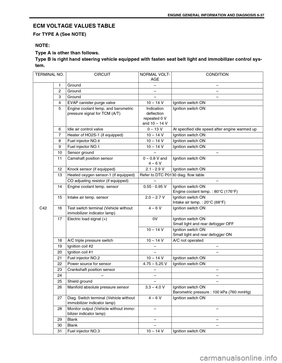
ECM VOLTAGE VALUES TABLE
For TYPE A (See NOTE)
NOTE:
Type A is other than follows.
Type B is right hand steering vehicle equipped with fasten seat belt light and immobilizer control sys-
tem.
TERMINAL NO. CIRCUIT NORMAL VOLT-
AGECONDITION
C421 Ground––
2 Ground––
3 Ground––
4 EVAP canister purge valve 10 – 14 V Ignition switch ON
5 Engine coolant temp. and barometric
pressure signal for TCM (A/T)Indication
deflection
repeated 0 V
and 10 – 14 VIgnition switch ON
6 Idle air control valve 0 – 13 V At specified idle speed after engine warmed up
7 Heater of HO2S-1 (if equipped) 10 – 14 V Ignition switch ON
8 Fuel injector NO.4 10 – 14 V Ignition switch ON
9 Fuel injector NO.1 10 – 14 V Ignition switch ON
10 Sensor ground––
11 Camshaft position sensor 0 – 0.8 V and
4 – 6 VIgnition switch ON
12 Knock sensor (if equipped) 2.1 - 2.9 V Ignition switch ON
13 Heated oxygen sensor-1 (if equipped) Refer to DTC P0130 diag. flow table
CO adjusting resistor (if equipped)––
14 Engine coolant temp. sensor 0.55 - 0.95 V Ignition switch ON
Engine coolant temp. : 80°C (176°F)
15 Intake air temp. sensor 2.0 – 2.7 V Ignition switch ON
Intake air temp. : 20°C (68°F)
16 Test switch terminal (Vehicle without
immobilizer indicator lamp)4 – 6 V Ignition switch ON
17 Electric load signal (+) 0V Ignition switch ON
Small light and rear defogger OFF
10 – 14 V Ignition switch ON
Small light and rear defogger ON
18 A/C triple pressure switch 10 – 14 V A/C not operated
19 Ignition coil #2––
20 Ignition coil #1––
21 Fuel injector NO.2 10 – 14 V Ignition switch ON
22 Power source for sensor 4.75 – 5.25 V Ignition switch ON
23 Crankshaft position sensor––
24–– –
25 Shield ground––
26 Manifold absolute pressure sensor 3.3 – 4.0 V Ignition switch ON
Barometric pressure : 100 kPa (760 mmHg)
27 Diag. Switch terminal (Vehicle without
immobilizer indicator lamp)4 – 6 V Ignition switch ON
28 Monitor output (Vehicle without immo-
bilizer indicator lamp)––
29 Blank––
30 Blank––
31 Fuel injector NO.3 10 – 14 V Ignition switch ON