Page 637 of 698
6E1-16 ENGINE AND EMISSION CONTROL SYSTEM
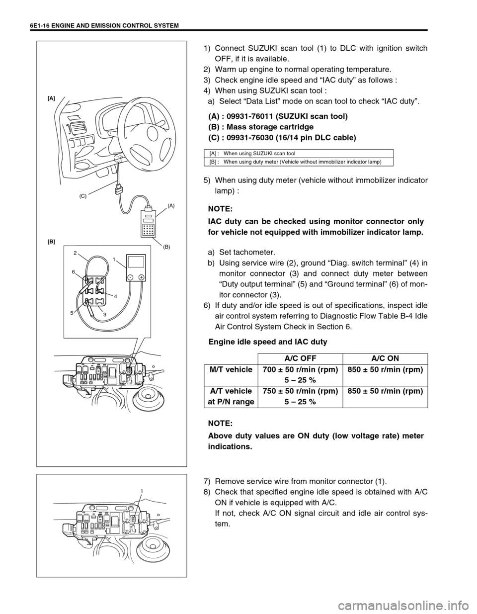
1) Connect SUZUKI scan tool (1) to DLC with ignition switch
OFF, if it is available.
2) Warm up engine to normal operating temperature.
3) Check engine idle speed and “IAC duty” as follows :
4) When using SUZUKI scan tool :
a) Select “Data List” mode on scan tool to check “IAC duty”.
(A) : 09931-76011 (SUZUKI scan tool)
(B) : Mass storage cartridge
(C) : 09931-76030 (16/14 pin DLC cable)
5) When using duty meter (vehicle without immobilizer indicator
lamp) :
a) Set tachometer.
b) Using service wire (2), ground “Diag. switch terminal” (4) in
monitor connector (3) and connect duty meter between
“Duty output terminal” (5) and “Ground terminal” (6) of mon-
itor connector (3).
6) If duty and/or idle speed is out of specifications, inspect idle
air control system referring to Diagnostic Flow Table B-4 Idle
Air Control System Check in Section 6.
Engine idle speed and IAC duty
7) Remove service wire from monitor connector (1).
8) Check that specified engine idle speed is obtained with A/C
ON if vehicle is equipped with A/C.
If not, check A/C ON signal circuit and idle air control sys-
tem.
[A] : When using SUZUKI scan tool
[B] : When using duty meter (Vehicle without immobilizer indicator lamp)
NOTE:
IAC duty can be checked using monitor connector only
for vehicle not equipped with immobilizer indicator lamp.
A/C OFF A/C ON
M/T vehicle 700 ± 50 r/min (rpm)
5 – 25 %850 ± 50 r/min (rpm)
A/T vehicle
at P/N range750 ± 50 r/min (rpm)
5 – 25 %850 ± 50 r/min (rpm)
NOTE:
Above duty values are ON duty (low voltage rate) meter
indications.
(C)
(A)
(B)
1 2
6
54
3-+
[A]
[B]
1
Page 641 of 698
6E1-20 ENGINE AND EMISSION CONTROL SYSTEM
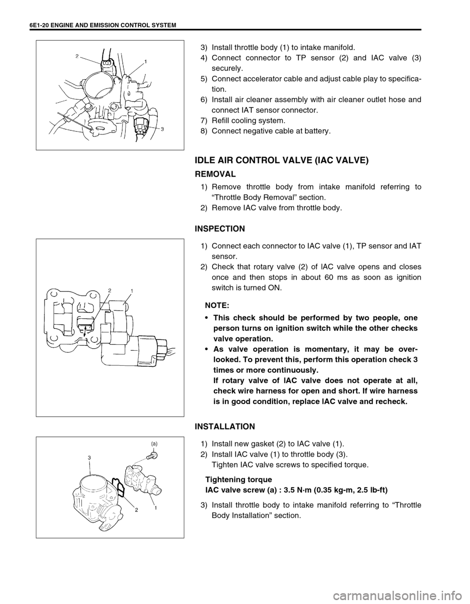
3) Install throttle body (1) to intake manifold.
4) Connect connector to TP sensor (2) and IAC valve (3)
securely.
5) Connect accelerator cable and adjust cable play to specifica-
tion.
6) Install air cleaner assembly with air cleaner outlet hose and
connect IAT sensor connector.
7) Refill cooling system.
8) Connect negative cable at battery.
IDLE AIR CONTROL VALVE (IAC VALVE)
REMOVAL
1) Remove throttle body from intake manifold referring to
“Throttle Body Removal” section.
2) Remove IAC valve from throttle body.
INSPECTION
1) Connect each connector to IAC valve (1), TP sensor and IAT
sensor.
2) Check that rotary valve (2) of lAC valve opens and closes
once and then stops in about 60 ms as soon as ignition
switch is turned ON.
INSTALLATION
1) Install new gasket (2) to IAC valve (1).
2) Install IAC valve (1) to throttle body (3).
Tighten IAC valve screws to specified torque.
Tightening torque
IAC valve screw (a) : 3.5 N·m (0.35 kg-m, 2.5 lb-ft)
3) Install throttle body to intake manifold referring to “Throttle
Body Installation” section.
NOTE:
This check should be performed by two people, one
person turns on ignition switch while the other checks
valve operation.
As valve operation is momentary, it may be over-
looked. To prevent this, perform this operation check 3
times or more continuously.
If rotary valve of lAC valve does not operate at all,
check wire harness for open and short. If wire harness
is in good condition, replace lAC valve and recheck.
Page 642 of 698
ENGINE AND EMISSION CONTROL SYSTEM 6E1-21
FUEL DELIVERY SYSTEM
FUEL PRESSURE INSPECTION
1) Relieve fuel pressure in fuel feed line referring to “Fuel Pres-
sure Relief Procedure” in Section 6.
2) Disconnect fuel feed hose from fuel delivery pipe.
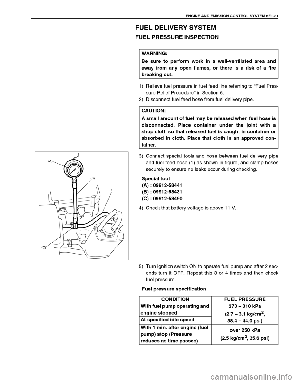
3) Connect special tools and hose between fuel delivery pipe
and fuel feed hose (1) as shown in figure, and clamp hoses
securely to ensure no leaks occur during checking.
Special tool
(A) : 09912-58441
(B) : 09912-58431
(C) : 09912-58490
4) Check that battery voltage is above 11 V.
5) Turn ignition switch ON to operate fuel pump and after 2 sec-
onds turn it OFF. Repeat this 3 or 4 times and then check
fuel pressure.
Fuel pressure specification WARNING:
Be sure to perform work in a well-ventilated area and
away from any open flames, or there is a risk of a fire
breaking out.
CAUTION:
A small amount of fuel may be released when fuel hose is
disconnected. Place container under the joint with a
shop cloth so that released fuel is caught in container or
absorbed in cloth. Place that cloth in an approved con-
tainer.
(A)
(B)
(C)1
CONDITION FUEL PRESSURE
With fuel pump operating and
engine stopped270 – 310 kPa
(2.7 – 3.1 kg/cm
2,
38.4 – 44.0 psi) At specified idle speed
With 1 min. after engine (fuel
pump) stop (Pressure
reduces as time passes)over 250 kPa
(2.5 kg/cm
2, 35.6 psi)
Page 643 of 698
6E1-22 ENGINE AND EMISSION CONTROL SYSTEM
6) Start engine and warm it up to normal operating tempera-
ture.
7) Measure fuel pressure at idling.
If measured pressure does not satisfy specification, refer to
“Diagnostic Flow Table B-3” in “Engine Diagnosis” section
and check each possibly defective part. Replace if found
defective.
8) After checking fuel pressure, remove fuel pressure gauge.
9) Remove special tools from fuel delivery pipe.
10) Connect fuel feed hose to fuel delivery pipe and clamp it
securely.
11) With engine “OFF” and ignition switch “ON”, check for fuel
leaks.
FUEL PUMP WITH PRESSURE REGULATOR
ON-VEHICLE INSPECTION
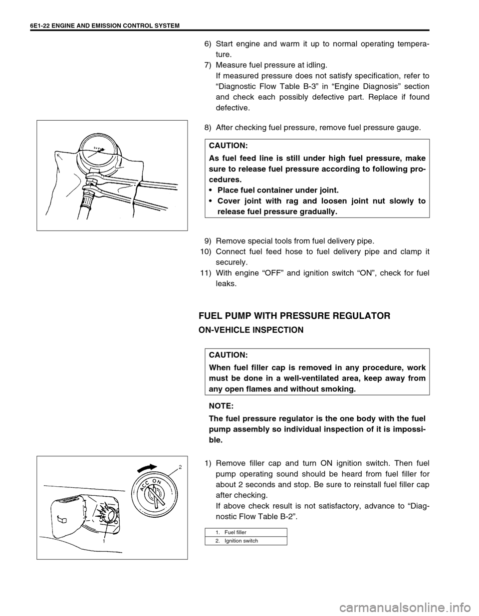
1) Remove filler cap and turn ON ignition switch. Then fuel
pump operating sound should be heard from fuel filler for
about 2 seconds and stop. Be sure to reinstall fuel filler cap
after checking.
If above check result is not satisfactory, advance to “Diag-
nostic Flow Table B-2”. CAUTION:
As fuel feed line is still under high fuel pressure, make
sure to release fuel pressure according to following pro-
cedures.
Place fuel container under joint.
Cover joint with rag and loosen joint nut slowly to
release fuel pressure gradually.
CAUTION:
When fuel filler cap is removed in any procedure, work
must be done in a well-ventilated area, keep away from
any open flames and without smoking.
NOTE:
The fuel pressure regulator is the one body with the fuel
pump assembly so individual inspection of it is impossi-
ble.
1. Fuel filler
2. Ignition switch
Page 644 of 698
ENGINE AND EMISSION CONTROL SYSTEM 6E1-23
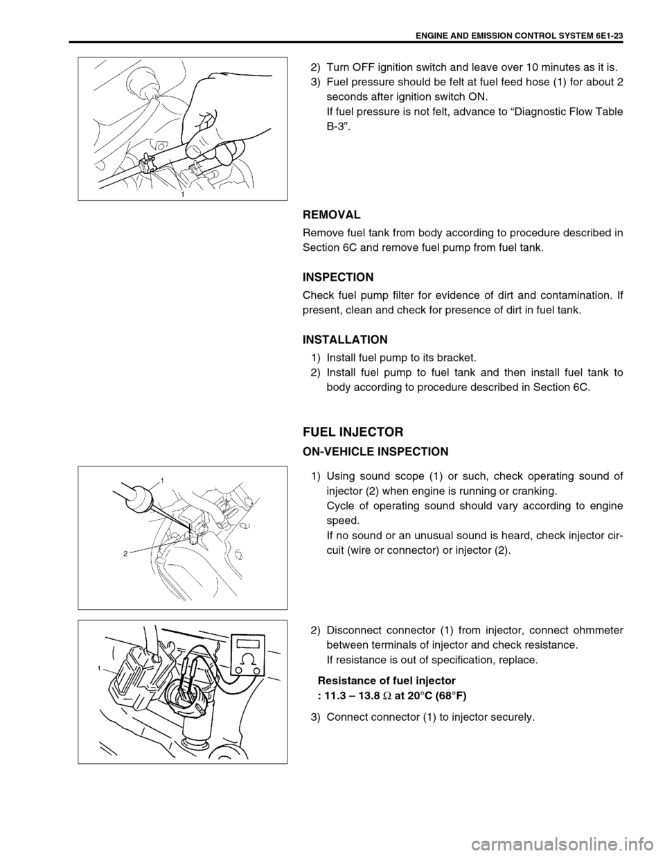
2) Turn OFF ignition switch and leave over 10 minutes as it is.
3) Fuel pressure should be felt at fuel feed hose (1) for about 2
seconds after ignition switch ON.
If fuel pressure is not felt, advance to “Diagnostic Flow Table
B-3”.
REMOVAL
Remove fuel tank from body according to procedure described in
Section 6C and remove fuel pump from fuel tank.
INSPECTION
Check fuel pump filter for evidence of dirt and contamination. If
present, clean and check for presence of dirt in fuel tank.
INSTALLATION
1) Install fuel pump to its bracket.
2) Install fuel pump to fuel tank and then install fuel tank to
body according to procedure described in Section 6C.
FUEL INJECTOR
ON-VEHICLE INSPECTION
1) Using sound scope (1) or such, check operating sound of
injector (2) when engine is running or cranking.
Cycle of operating sound should vary according to engine
speed.
If no sound or an unusual sound is heard, check injector cir-
cuit (wire or connector) or injector (2).
2) Disconnect connector (1) from injector, connect ohmmeter
between terminals of injector and check resistance.
If resistance is out of specification, replace.
Resistance of fuel injector
: 11.3 – 13.8
Ω at 20°C (68°F)
3) Connect connector (1) to injector securely.
Page 646 of 698
ENGINE AND EMISSION CONTROL SYSTEM 6E1-25
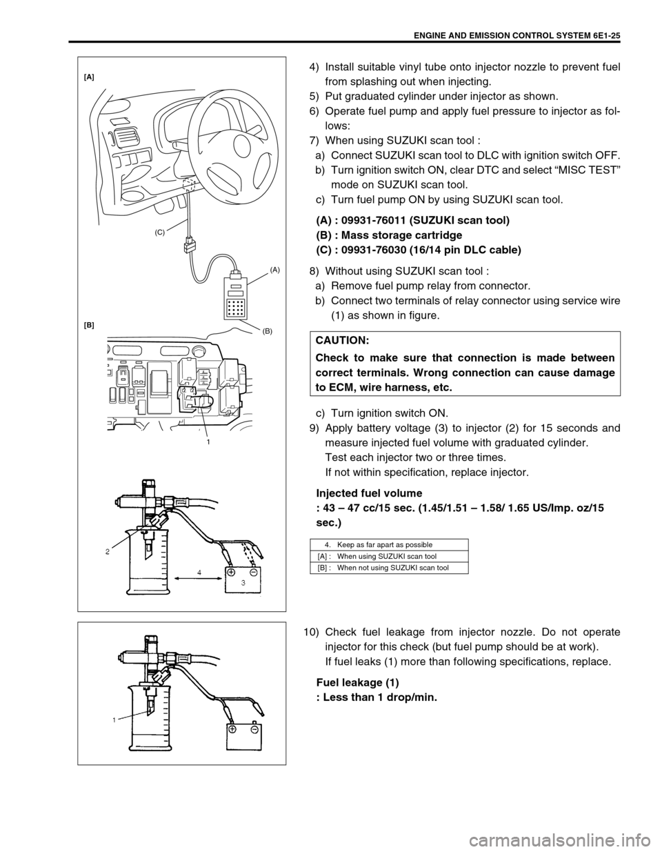
4) Install suitable vinyl tube onto injector nozzle to prevent fuel
from splashing out when injecting.
5) Put graduated cylinder under injector as shown.
6) Operate fuel pump and apply fuel pressure to injector as fol-
lows:
7) When using SUZUKI scan tool :
a) Connect SUZUKI scan tool to DLC with ignition switch OFF.
b) Turn ignition switch ON, clear DTC and select “MISC TEST”
mode on SUZUKI scan tool.
c) Turn fuel pump ON by using SUZUKI scan tool.
(A) : 09931-76011 (SUZUKI scan tool)
(B) : Mass storage cartridge
(C) : 09931-76030 (16/14 pin DLC cable)
8) Without using SUZUKI scan tool :
a) Remove fuel pump relay from connector.
b) Connect two terminals of relay connector using service wire
(1) as shown in figure.
c) Turn ignition switch ON.
9) Apply battery voltage (3) to injector (2) for 15 seconds and
measure injected fuel volume with graduated cylinder.
Test each injector two or three times.
If not within specification, replace injector.
Injected fuel volume
: 43 – 47 cc/15 sec. (1.45/1.51 – 1.58/ 1.65 US/Imp. oz/15
sec.)
10) Check fuel leakage from injector nozzle. Do not operate
injector for this check (but fuel pump should be at work).
If fuel leaks (1) more than following specifications, replace.
Fuel leakage (1)
: Less than 1 drop/min. CAUTION:
Check to make sure that connection is made between
correct terminals. Wrong connection can cause damage
to ECM, wire harness, etc.
4. Keep as far apart as possible
[A] : When using SUZUKI scan tool
[B] : When not using SUZUKI scan tool
(C)
(A)
(B)
1 [A]
[B]
Page 647 of 698
6E1-26 ENGINE AND EMISSION CONTROL SYSTEM
INSTALLATION
For installation, reverse removal procedure and note following
precautions.
Replace injector O-ring (1) with new one using care not to
damage it.
Check if cushion (2) is scored or damaged. If it is, replace
with new one.
Apply thin coat of fuel to O-rings (1) and then install injectors
(3) into delivery pipe (4) and intake manifold.
Make sure that injectors (3) rotate smoothly (6). If not, proba-
ble cause is incorrect installation of O-ring (1). Replace O-
ring (1) with new one.
Tighten delivery pipe bolts (5) and make sure that injectors
(3) rotate smoothly (6).
Tightening torque
Delivery pipe bolts (a) : 28 N·m (2.8 kg-m, 20.5 lb-ft)
After installation, with engine “OFF” and ignition switch “ON”,
check for fuel leaks around fuel line connection.5, (a)
4
1
3 2
Page 655 of 698
6E1-34 ENGINE AND EMISSION CONTROL SYSTEM
FUEL CUT OPERATION
INSPECTION
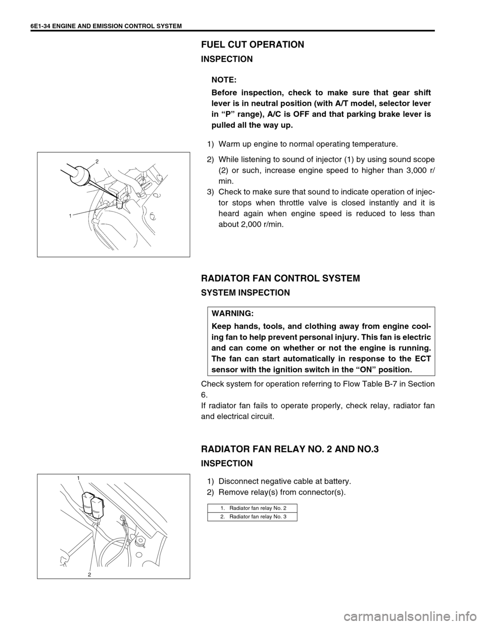
1) Warm up engine to normal operating temperature.
2) While listening to sound of injector (1) by using sound scope
(2) or such, increase engine speed to higher than 3,000 r/
min.
3) Check to make sure that sound to indicate operation of injec-
tor stops when throttle valve is closed instantly and it is
heard again when engine speed is reduced to less than
about 2,000 r/min.
RADIATOR FAN CONTROL SYSTEM
SYSTEM INSPECTION
Check system for operation referring to Flow Table B-7 in Section
6.
If radiator fan fails to operate properly, check relay, radiator fan
and electrical circuit.
RADIATOR FAN RELAY NO. 2 AND NO.3
INSPECTION
1) Disconnect negative cable at battery.
2) Remove relay(s) from connector(s).NOTE:
Before inspection, check to make sure that gear shift
lever is in neutral position (with A/T model, selector lever
in “P” range), A/C is OFF and that parking brake lever is
pulled all the way up.
WARNING:
Keep hands, tools, and clothing away from engine cool-
ing fan to help prevent personal injury. This fan is electric
and can come on whether or not the engine is running.
The fan can start automatically in response to the ECT
sensor with the ignition switch in the “ON” position.
1. Radiator fan relay No. 2
2. Radiator fan relay No. 3
1
2